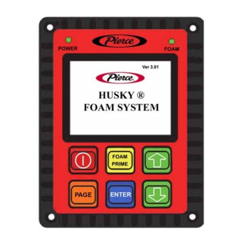
Pierce CP600 User manual

CP CORNER
ASSEMBLY MANUAL
APRIL 2015
07902-0415


CP CORNER Assembly
Section xi Table of Contents..................................................................
Section 1 Corner Structure
Outer Leg Assembly..........................................................................
Truss Compression Brace...................................................................
Cat Walk Assembly............................................................................
Tower Panels....................................................................................
Tower Valve Box...............................................................................
Corner Tower Steering.......................................................................
Tower Inner Legs.............................................................................
Wheel Struts....................................................................................
Steering Pot ASM 1...........................................................................
Steering Pot ASM 2...........................................................................
Steering Pot.....................................................................................
Tower Guidance................................................................................
Hinge Tower Swing...........................................................................
Hinge Tower Connection....................................................................
Hinge Tower Ring Lock Assembly........................................................
Hinge Tower Pot Switch.....................................................................
Hinge Tower Panel............................................................................
Hinge Tower Junction Box..................................................................
Remote Expansion Chamber...............................................................
Section 2 Machine Setup
Machine Setup.................................................................................
BOP Operation.................................................................................
Hinge Tower VFD Parameters.............................................................
Corner Drive Tower VFD Parameters...................................................
Wire Layout.....................................................................................
Section 3 Electrical
A Word About Grounding...................................................................
Corner Tower Control Panel Wiring Diagram..........................................
Corner Tower Control Panel Field Wiring Detail......................................
Drive Panel Wiring Diagram................................................................
Hinge Tower Junction Box Wiring Diagram............................................
Hinge Tower Wiring Diagram..............................................................
Corner Panel Parts............................................................................
Valve Box Parts................................................................................
Valve Box Wiring Diagram..................................................................
Compressor JB.................................................................................
Compressor Plumbing........................................................................
Oscillator Panel Wiring Diagram..........................................................
Buried Guidance JB Reciever Wiring Diagram........................................
Solar Power Oscillator Option.............................................................
xi-1
1-3
1-4
1-6
1-8
1-10
1-12
1-14
1-16
1-18
1-20
1-22
1-24
1-27
1-28
1-30
1-32
1-34
1-36
1-38
2-2
2-3
2-5
2-7
2-9
3-3
3-4
3-6
3-8
3-10
3-11
3-12
3-14
3-17
3-18
3-19
3-20
3-21
3-22
TABLE OF CONTENTS
xi-1

TABLE OF CONTENTS
Section 4 Sprinkler Control
Sprinkler Zones.............................................................................
Section 5 Panel Operation
Status Screen 1...........................................................................
Status Screen 2...........................................................................
Steer Screen...............................................................................
Setup Screen 1............................................................................
Setup screen 2.............................................................................
Setup Screen 3............................................................................
Setup Screen 4.............................................................................
Setup Screen 5.............................................................................
End Gun Screen............................................................................
Corner Steering.............................................................................
Sprinkler Control...........................................................................
4-2
5-2
5-3
5-4
5-5
5-6
5-7
5-8
5-10
5-11
5-12
5-13
xi-2

Corner Structure

Corner Structure

Corner Structure
Corner Assembly Manual
Section 1-3
© Pierce Corporation
April 2015
1
2
3
4
5
6
7
Outer Leg Assembly
Item Part# Qty Description
1 02031-11 24 Lock Nut 5/8
2 11072-11 2 Tower Crosstie 27-15/16”
3 11071-11 2 Tower Crosstie 20-7/8”
4 11070-11 2 Tower Crosstie 13-13/16”
5 02068-02 24 Hex Bolt 5/8 x 1-1/2”
6 11049-11 1 Corner Frame Asm
7 11073-11 4 Outer Tower Leg 92”

Corner Structure
Corner Assembly Manual
Section 1-4
© Pierce Corporation
April 2015
Truss Compression Brace
1
2
3
4
5
6
7
89
10
11
See Detail A. for
parts list
Item Part# Qty Description
1 02031-07 16 Lock Nut 1/2”
2 10128-11 2 Half Band 6-5/8”
3 10742-11 8 HD Anti Buckle Clamp
4 02066-06 2 Hex Bolt 1/2 x 2
5 10747-11 2 Truss Comp Brace 194- 13/16”
6 11137-11 2 Tower Comp Brace 262 3/4”
7 11094-11 1 Truss Crosstie
8 11082-11 1 Comp Brace Crosstie 94”
9 02510-10 4 Flange Lock Nut 3/8”
10 02075-10 2 U Bolt 3/8x3-1/8 L x 2-1/2 W
11 11091-11 2 Comp Brace Leg 69-3/8”

Corner Structure
Corner Assembly Manual
Section 1-5
© Pierce Corporation
April 2015
Compression Brace
1
2
3
4
4
7
8
6
5
9
10
Detail A.
# 1 V- Jack
Item Part# Qty Description
1 11066-11 2 Tower Comp Brace
2 02031-11 6 Lock Nut 5/8
3 02066-04 1 Hex Bolt 1/2” x 1-1/2”
4 02031-07 2 Lock Nut 1/2”
5 10085-11 1 Truss Rod Bracket Top
6 10086-11 1 Truss Rod Bracket Bottom
7 11093-11 2 Comp Brace Spacer
8 02066-13 4 Hex Bolt 1/2” x 2-1/2”
9 11094-11 1 Comp Brace Crosstie
10 02068-02 6 Hex Bolt 5/8” x 1-1/2”
Truss Compression Brace Stack

Corner Structure
Corner Assembly Manual
Section 1-6
© Pierce Corporation
April 2015
Cat Walk Assembly A.
4
2
6
53
1
Item Part# Qty Description
1 11074-11 2 PLATFORM #1 67
2 11075-11 3 PLATFORM #2 113-3/4
3 11076-11 2 PLATFORM #3 42-1/2
4 11077-11 2 PLATFORM #4 71-5/16
5 11078-11 2 PLATFORM #5 47-13/16
6 02031-07 14 Lock Nut 1/2”

Corner Structure
Corner Assembly Manual
Section 1-7
© Pierce Corporation
April 2015
Cat Walk Assembly B.
5
4
32
1
Note: Do not install nut at this time
Item Part# Qty Description
1 11083-11 1 PLATFORM GRATING 114
2 02066-06 4 HEX BOLT 1/2 X 2
3 02031-07 6 LOCK NUT 1/2
4 02066-04 4 HEX BOLT 1/2 x 1-1/2
5 11047-11 2 HALF BAND

Corner Structure
Corner Assembly Manual
Section 1-8
© Pierce Corporation
April 2015
Tower Panels
1
2
3
4
5
6
78
9

Corner Structure
Corner Assembly Manual
Section 1-9
© Pierce Corporation
April 2015
Item Part# Qty Description
1 02066-06 4 HEX BOLT G5 1/2 X 2
2 11047-11 2 HALF BAND
3 11045-11 4 PANEL MNT 26-5/8
4 02064-15 8 HEX BOLT X 3/8 X 1/2
5 11046-11 4 PANEL X-BRACE 17-3/4
6 02066-04 10 HEX BOLT 1/2 X 1-1/2
7 02031-07 14 LOCK NUT 1/2
8 11102-41 1 TOWER DRIVE PANEL SS
9 11103-41 1 TOWER MAIN PANEL SS
Tower Panels

Corner Structure
Corner Assembly Manual
Section 1-10
© Pierce Corporation
April 2015
1
3
4
Tower Valve Box
2

Corner Structure
Corner Assembly Manual
Section 1-11
© Pierce Corporation
April 2015
Tower Valve Box
Item Part# Qty Description
1 11116-11 2 VALVE BOX MOUNT BAR
2 02031-03 8 LOCK NUT 5/16
3 02019-02 8 HEX BOLT 5/16 X 1
4 11106-01 1 VALVE BOX

Corner Structure
Corner Assembly Manual
Section 1-12
© Pierce Corporation
April 2015
1
17
2
3
5
6
7
89
10
12 14
13
15
16
18
11
Corner Tower Steering
4

Corner Structure
Corner Assembly Manual
Section 1-13
© Pierce Corporation
April 2015
Corner Tower Steering
Item Part# Qty Description
1 02233-09 2 GB 50:1 NON TOW SHORT SHAFT
2 02234-07 16 NUT WHEEL UMC
3 11041-11 2 CORNER STEER SPOOL 30
4 02066-15 4 HEX BOLT 1/2 X 4 NF
5 11068-11 2 CORNER BEARING CAP
6 11069-01 4 CORNER BEARING SYNTHETIC
7 11062-11 2 CORNER KNEE BRACE
8 02068-02 8 HEX BOLT 5/8 X 1-1/2
9 02298-01 2 DL COVER 57
10 02248-03 4 CLAMP HOSE #26-1091-3 1.25
11 10917-21 2 DRIVE LINE 61.5 X 7/8
12 02173-02 4 FLEX UMC 1 X 7/8
13 02234-06 1 MOTOR .75 HP 60:1 POWER SAVER
14 02298-03 4 DL BELL PIERCE
15 02064-02 4 HEX BOLT 3/8 X 1-1/2
16 02031-05 4 LOCK NUT 3/8
17 02031-11 8 LOCK NUT 5/8
18 02066-03 10 HEX BOLT 1/2 X 1-1/4

Corner Structure
Corner Assembly Manual
Section 1-14
© Pierce Corporation
April 2015
2
1
3
45
6
Tower Inner Legs
Other manuals for CP600
1
Table of contents
Other Pierce Irrigation System manuals