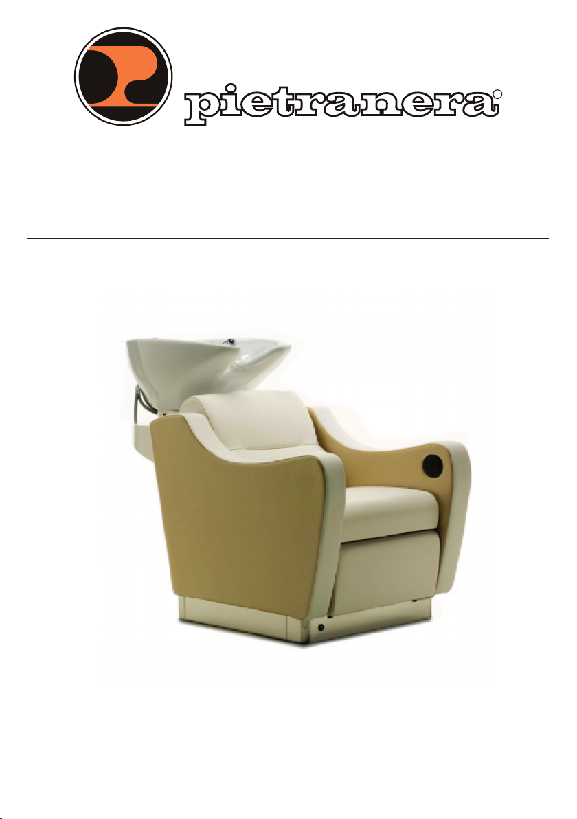
pietranera WEN Relax Elettrico Parts list manual

R
ITALIAN DESIGN & PRODUCTION
Istruzioni per l’installazione, l’uso e la manutenzione
Instructions for installation, use and maintenance
LAVAGGIO - WASHING UNIT
WEN


1
Istruzioni per l’installazione, l’uso e la manutenzione - Instructions for installation, use and maintenance
PREMESSA - INTRODUCTION
Grazie per avere scelto un prodotto Pietranera, siamo certi che ne sarete pienamente soddisfatti.
I prodotti Pietranera sono costruiti seguendo rigorosi standard qualitativi ed utilizzano esclusivamente
componenti di qualità.
Ogni lavaggio al momento della spedizione viene sottoposto ad una scrupolosa serie di collaudi
relativi a funzionalità e sicurezza.
Vericare che il lavaggio, durante il trasporto, non abbia subito danni che potrebbero pregiudicarne
il funzionamento e la sicurezza.
Per ottenere la massima afdabilità e durata del lavaggio con le migliori prestazioni, si consiglia di
seguire scrupolosamente le istruzioni contenute nel presente manuale.
Questo manuale è realizzato in modo da permettere di utilizzare al meglio e nella massima sicurezza
il lavaggio.
Questo manuale costituisce quindi parte integrante del lavaggio, deve essere conservato con
cura per tutto l’arco della durata del lavaggio e deve accompagnare il lavaggio stesso qualora
venga ceduto ad un nuovo utilizzatore.
Per evitare quindi qualsiasi inconveniente è necessario leggere attentamente il presente manuale
prima di effettuare qualsiasi operazione sul lavaggio e attenersi scrupolosamente a quanto in esso
specicato. La Ditta costruttrice declina ogni responsabilità per danni dovuti a negligenza e/o alla
mancata osservanza di quanto descritto nel presente manuale.
Fermo restando le caratteristiche tecniche principali e di sicurezza, la Ditta costruttrice, per ragioni
di continua evoluzione tecnica e tecnologica, si riserva il diritto di apportare, senza preavviso,
modiche al lavaggio, senza per questo incorrere in alcuna sanzione.
Ogni riproduzione parziale o totale del seguente manuale, dai testi alle illustrazioni in esso contenuti,
è vietata a norma di legge.
Per ogni controversia è competente il Foro di Reggio Emilia (Italy).
Thank you for chosing a Pietranera product, we are condent you will be fully satised with us.
Pietranera products are manufactured on the basis of very high quality levels,and by high quality
components only.
Each back wash before its shipment must pass a series of strict tests concerning its performance
and safety level.
Please check immediately that your wash unit has not been damaged during the transport In
order to obtain the highest working level and the longest possible life we suggest to follow these
instructions in detail. This instructions manual has been written in order to get the best of the product,
and it must be considered as a part of the product itself, it must be preserved during all the wash
unit life and delivered together with the unit if the unit is sold.
The manufacturing company declines any responsibility in case of any damage which may occurr
during a wrong usage or any usage different from the one described in this manual.
Even if the main safety and technical features will remain the same, the manufacturing company
has the right to make any improvement or change to the wash unit without running the risk of any
sanction.
It is forbidden by law any partial or total copy of this manual texts or photos.
Any possible litigation would be discussed in Reggio Emilia Court in Italy.

2Istruzioni per l’installazione, l’uso e la manutenzione - Instructions for installation, use and maintenance
INDICE - INDEX
PREREQUISITI - SERVICE REQUIREMENT ....................................................................................................3
CARATTERISTICHE TECNICHE - TECHNICAL SPECIFICATIONS .................................................................4
CONDIZIONI AMBIENTALI - ENVIRONMENTAL CONDITIONS REQUIREMENT.........................................4
DIMENSIONI - DIMENSIONS .......................................................................................................................4
INSTALLAZIONE - INSTALLATION
PIANO DI INSTALLAZIONE - INSTALLATION PLAN .....................................................................................5
ISTRUZIONI - INSTRUCTION.........................................................................................................................6
MONTAGGIO DEL LAVABO - BASIN ASSEMBLY .......................................................................................7
MONTAGGIO DEL MISCELATORE - MIXER ASSEMBLY .............................................................................8
MONTAGGIO DELLA DOCCETTA - SHOWER ASSEMBLY.........................................................................9
MONTAGGIO PILETTA SU LAVABO - DRAIN ASSEMBLY..........................................................................11
INSTALLAZIONE - INSTALLATION ..............................................................................................................12
Preparazione - Pre-installation steps .................................................................................................12
Fissaggio del lavaggio - Wash unit xing..........................................................................................12
Installazione a terra - Floor drain installation....................................................................................13
Installazione a parete - Side drain installation.................................................................................15
USO - USE
USO - USE..................................................................................................................................................17
COMANDI RELAX - RELAX CONTROL ....................................................................................................18
COMANDI AIR - AIR CONTROL ..............................................................................................................19
MANUTENZIONE ORDINARIA - ROUTINE MAINTENANCE......................................................................20
Seduta - Armchair...............................................................................................................................20
Gruppo alzagambe - Relax movement...........................................................................................20
Gruppo lavabo - Basin unit................................................................................................................21
Pulizia delle superci - Surface cleaning ..........................................................................................22
IDENTIFICAZIONE DELL’APPARECCHIO - WASHING UNIT IDENTIFICATION .........................................22
DIAGNOSTICA - DIAGNOSTIC ................................................................................................................23

3
Istruzioni per l’installazione, l’uso e la manutenzione - Instructions for installation, use and maintenance
PREREQUISITI - SERVICE REQUIREMENT
Per una corretta e sicura installazione dell’apparecchio vanno rispettate le seguenti prescrizioni:
• Il pavimento deve essere conforme alle Norme DIN 1055 B 1.3 e DIN 18560 T 1.
• L’impianto elettrico deve essere conforme alle Norme CEI 64.4, realizzato con conduttori di
protezionea differenziale (con indice <30mA) da 250V / 16A.
• Non collegare dispositivi che non sono specicati come facenti parte del sistema.
• La messa a terra, in particolare, deve essere conforme all’art. 3.2.01 delle Norme suddette.
• Il ssaggio a terra deve essere eseguito con tasselli del diametro minimo di 8mm.
Il fabbricante non si assume la responsabilità della sicurezza e dell’afdabilità dell’apparecchio se:
• Le operazioni di installazione e riparazione non sono state effettuate da tecnici autorizzati.
• L’installazione generale ed elettrica del locale non è conforme alle prescrizioni sopra riportate.
• L’apparecchio non è stato installato conformemente al presente manuale.
• L’apparecchio non è utilizzato conformemente al presente manuale.
A correct and safe installation needs what follows:
• The oor must be in line with the DIN 1055 B 1.3 and DIN 18560 T 1. Rules.
• The electric system must be in line with the CEI 64. 4 rules, made of differential protection wire
(value < 30mA) from 250V/16 A on.
• The product must not be connected with any surplus part which is not listed in the use manual
• The grounding must be in line with the act 3.2.01 of the above-mentioned rules.
• The oor xing must be done by small blocks with a diameter of at least 8 mm.
The manufacturer declines all responsibility for the product safety and reliability if:
• Anyinstallationorrepairisnotmadebyatrainedtechnician.
• The salon where the washing unit is installed and its electrical system are not in line with the
abovetechnicalspecications.
• Theproductisnotinstalledfollowingthismanualinstructions.
• Theuseoftheproductisnotinlinewiththismanualinstructions.

4Istruzioni per l’installazione, l’uso e la manutenzione - Instructions for installation, use and maintenance
CARATTERISTICHE TECNICHE - TECHNICAL SPECIFICATIONS
CONDIZIONI AMBIENTALI - ENVIRONMENTAL CONDITIONS REQUIREMENT
DIMENSIONI - DIMENSIONS
1280
1675
460
900 700
570
500
500
300
680
960
490
Lunghezza con alzagambe - with leg rest
altezza seduta
seat height
altezza collo
neck height
Modello lavaggio
Unit model
Tensione nominale
Rated voltage
Frequenza nominale
Rated frequency
Potenza nominale
Rated power
Modo operativo
intermittente
Rated cycle
WEN Relax Elettrico
WEN Electrical Relax 220V ~ ±10% 50/60 Hz 110VA 2 min. ON/5min.OFF
WEN Air 220V ~ ±10% 50/60 Hz 140VA 20 min. ON/5min.OFF
Condizioni ambientali di trasporto e magazzinaggio
• Temperatura ambiente da -40°C a +70°C.
• Umidità relativa dal 10% al 90%.
Condizioni ambientali di utilizzo
• Temperatura ambiente da +5°C a +50°C.
• Umidità relativa max 80%.
Transportandstockageconditionsrequired
• Environmental temperature: from 40° up to 70° C.
• Relative humidity from 10% to 90%.
Environmentalspecicationsrequired
• Environmental temperature: from +5°C to+50°C.
• Relative humidity max 80%.

5
Istruzioni per l’installazione, l’uso e la manutenzione - Instructions for installation, use and maintenance
PIANO DI INSTALLAZIONE - INSTALLATION PLAN
12
3
4
636
360
600600
1465
678
100 x 100 mm
Area foro pavimento
Floor cut out area
Larghezza piede lavaggio
Foot width wash
Distanza dal muro:
Min. 1200 mm
(Compresa dello
spazio lavoro di 600 mm)
Distance to the wall:
Min. 1200 mm
(Including working
space 600 mm)
Larghezza piede lavaggio
Foot width wash
Centro impianto idraulico
Center of drain
N° 2 asole fissaggio ø8mm
N° 2 holes for grounding ø8mm
Distanza dal muro:
Min. 350 mm
Distanza dal lavaggio:
Min. 700 mm
Distance to the wall:
Min. 350 mm
Distance to the wash unit:
Min. 700 mm
ATTENZIONE! Prima di ssare il lavaggio in batteria con scarico laterale, effettuare l’apertura della ancata.
ATTENTION! If you must install your back wash with a side drain or in line please follow these steps.
1 = Calda 3/8” - Warm 3/8”
2 = Fredda 3/8” - Cold 3/8”
3 = Scarico ø 40mm - Drain ø 40mm
4 = Uscita cavi elettrici (dove richiesto)- Electric cables outlet (when needed)
Cavo/Cable 3x1 (600 mm) - 220/240 V - 50 Hz/60 Hz
Disposizione Impianti
Disposition system
10
10
12
3
4

6Istruzioni per l’installazione, l’uso e la manutenzione - Instructions for installation, use and maintenance
PIANO DI INSTALLAZIONE - INSTALLATION PLAN
530
600600
600
400
200
Distanza dal muro:
Min. 1130 mm
(Compresa dello
spazio lavoro di 600 mm)
Distance to the wall:
Min. 1130 mm
(Including working
space 600 mm)
ISTRUZIONI - INSTRUCTION
1= Rilevare l’altezza da terra dello scarico a parete.
2= Aprire il carter posteriore del lavaggio.
3= All’interno della spalla trovare l’asola preesistente
ed effettuare un foro di centratura all’altezza
rilevata.
4= All’esterno della spalla ssare la angia in
dotazione con le apposite viti.
5 = Effettuare l’apertura della ancata.
1 = Mesure the height on the wall at which the drain
must be connected to.
2 = Open up the back carter of the wash unit.
3 = From the back side of your new wash unit look
for the inner side holes already arranged for this
purpose and drill them at the needed height.
4 = Now go outside, x and screw the ange of your
kit on the outside wall of your back wash.
5 = Once the ange is perfectly xed on the side,
all the part inside the round ange itself must
be removed thus leaving the right open hole to
install the side drain system.

7
Istruzioni per l’installazione, l’uso e la manutenzione - Instructions for installation, use and maintenance
2
1
3
MONTAGGIO DEL LAVABO - BASIN ASSEMBLY
Preparazione
1) Togliere il carter posteriore (1) svitando le 2 viti.
Remove the rear cover (1) by loosening the 2 screws.
2)
Posizionare la ceramica (2) sopra il gruppo oscillante avendo cura di stringere con cautela i 4 tasselli in
gomma
(3)
.
Place the ceramic part (2) over the oscillating unit, carefullytighteningthe4rubberplugs(3).

8Istruzioni per l’installazione, l’uso e la manutenzione - Instructions for installation, use and maintenance
MONTAGGIO DEL MISCELATORE - MIXER ASSEMBLY
3 cm
1) Inserire la guarnizione in gomma no a
battuta con il corpo miscelatore.
Insert the rubber gasket until it is up against
the mixer body.
2) Posizionare il corpo miscelatore sulla vasca
facendo passare i tre tubi essibili nel foro
tenendo quello più lungo centrale.
Place the mixer body on the basin, passing
the three exible tubes in the hole, keeping
the longest one in the middle.
3) Fissare il corpo miscelatore alla vasca; far passare i tubi all’interno del collare.
Fix the mixer body to the basin; get the tubes through the collar.

9
Istruzioni per l’installazione, l’uso e la manutenzione - Instructions for installation, use and maintenance
MONTAGGIO DELLA DOCCETTA - SHOWER ASSEMBLY
Caratteristiche Tecniche
Pressione di collaudo = 15 bar
Alimentazione acqua fredda = indice blu a
destra
Alimentazione acqua calda = indice rosso a
sinistra
Limiti di impiego secondo UNI 10234 (EN 817):
Pressione = MIN. 0.5 bar MAX. 10 bar
Temperatura = MAX. 90°
Limiti di impiego raccomandati da UNI 10234 (EN
817) per un buon funzionamento del rubinetto
Pressione = MIN. 0.5 bar MAX. 5 bar
Temperatura = MAX. 65°C
Avvertenze:
- È necessario risciacquare accuratamente tutte
le condutture dell’impianto per evitare danni
alla rubinetteria causati dai residui presenti nelle
tubazioni.
- Per pressioni d’uso superiori ai 5 bar, si
raccomanda di installare un riduttore di
pressione.
- Si consiglia inoltre, di installare un ltro
centralizzato per acque cariche di impurità.
TechnicalSpecications
Test pressure = 15 bar
Cold water supply = bluepointeronyourright
Warm water supply = red pointer on your left
UsagelimitaccordingtoUNI10234(EN817):
Pressure = MIN. 0.5 bar MAX. 10 bar
Temperature = MAX. 90°
TapusagelimitaccordingtoUNI10234(EN817)
Pressure = MIN. 0.5 bar MAX. 5 bar
Temperature = MAX. 65°C
Warning:
- To avoid any tap damage due to any pipe
waste please wash accurately all the plumbing.
- Please install a pressure reducer if the pressure is
higher than 5 bars.
- Please install a main lter for water waste.
1) Fissare la forcella al lavabo - Fix the fork to the washbasin.
2)
Avvitare il tubo essibile più lungo del gruppo
miscelatore alla forcella.
Tighten the longest exible tube of the mixer unit
to the fork.

10 Istruzioni per l’installazione, l’uso e la manutenzione - Instructions for installation, use and maintenance
MONTAGGIO DELLA DOCCETTA - SHOWER ASSEMBLY
3) Avvitare il tubo argento alla doccetta e alla forcella. Mantenere il tubo argento ortogonale alla forcella.
Tighten the silver tube to the shower and the fork. Keep the silver tube at right angles to the fork.
4) Serrare tutti i componenti.
Tighten all the components.

11
Istruzioni per l’installazione, l’uso e la manutenzione - Instructions for installation, use and maintenance
MONTAGGIO PILETTA SU LAVABO - DRAIN ASSEMBLY
Montare la piletta sul lavabo come da gura.
1) Griglia
2) Vite di serraggio
3) Corpo scarico INOX
4) Stucco
5) Lavabo
6) Guarnizione
7) Corpo scarico
8) Guarnizione OR
9) Tubo scarico corrugato estensibile
Min 430 - Max 1300 mm
Mount the drain onto the washbasin
as shown in the gure.
1) Grid
2) Tightening screw
3) Stainless steel drain body
4) Plastering
5) Washbasin
6) Gasket
7) Draining cup
8) OR Gasket
9) Extensible-exible drainage pipe
Min 430 - Max 1300 mm
1
2
3
4
5
6
7
8
9

12 Istruzioni per l’installazione, l’uso e la manutenzione - Instructions for installation, use and maintenance
1 (X 2)
2 (X 2)
3 (X 2)
Preparazione - Pre-Installation Steps
1) Togliere le parti superiori e laterali dell’imballo lasciando il lavaggio montato sul pallet in maniera che sia
più facilmente trasportabile. Rimuovere le protezioni del lavaggio e anche gli eventuali accessori contenuti
nell’imballo stesso.
- Take away the upper and side part of the package just leaving the washing unit on the pallet so that it is
easier to move it.
2) Segnare sul pavimento la posizione dell’unità lavaggio e dei fori per le viti di ssaggio.
- Mark the oor the position of the wash unit and the xing holes.
Fissaggio del lavaggio - Washunitxing
1) Svitare le viti (1) che bloccano il carter posteriore. Svitare le 2 viti di ssaggio del lavaggio al pallet (2) e
posizionare il lavaggio nel punto predisposto per l’installazione.
- Unscrew the xing screw (1) of the rear carter. Unscrew the washing unit from the pallet (2) and move the
wash unit to the previously preset place.
2) Posizionare i 2 dischetti in Nylon forniti (3) sotto la base del lavaggio e ssarlo a terra con i tasselli ad
espansione adatti al tipo di materiale di cui è costituito il pavimento, utilizzando i quattro fori predisposti.
- Place the 4 small nylon disks (3) (included in the installation set) under the washing base and x the washing
unit to the ground by some screw anchors of the right material for your oor using the previously preset
holes.
INSTALLAZIONE - INSTALLATION

13
Istruzioni per l’installazione, l’uso e la manutenzione - Instructions for installation, use and maintenance
Predisposizione
allacciamento idraulico
Predisposition
drain main power
INSTALLAZIONE - INSTALLATION
Installazione a terra
ATTENZIONE!
Se l’installazione prevede l’entrata delle
alimentazioni a parete oppure in batteria
effettuare l’apertura della ancata (punto 2).
1) Eseguire tutte le installazioni del gruppo
idrico mediante raccordi idraulici ø 3/8”. È
consigliabile prevedere una saracinesca di
chiusura a monte di ogni raccordo.
Gli allacciamenti alla rete fognaria sono
effettuati mediante un tubo di scarico ø 40.
Floor drain installation
ATTENTION!
If you must install your back wash with a side
drain or in line please follow these steps:
1) Make all the installations of the water supply
by connectors with a 3/8”diameter. It is
better to arrange a closing valve upstream
every connector. As far as the connection
to the sewer system is concerned, it is made
by a 40 mm diameter sewer pipe.
1 = Calda 3/8” - Warm 3/8”
2 = Fredda 3/8” - Cold 3/8”
3 = Scarico ø 40mm - Drain ø 40mm
4 = Uscita cavi elettrici (dove richiesto)
Electric cables outlet (when needed)
Cavo/Cable 3x1 (600 mm) - 220/240 V - 50 Hz/60 Hz
Disposizione Impianti
Disposition system
10
10
12
3
4

14 Istruzioni per l’installazione, l’uso e la manutenzione - Instructions for installation, use and maintenance
INSTALLAZIONE - INSTALLATION
2)
Connect the unit to the electric system by opening
the branch point box (1) and then connecting the
net wire to the joint in the ground points N- L-T.
Make then a general test of the unit.
ATTENTION:
- Please in order to avoid any accident chose right
wires for this datum.
- The seat in adjustable, therefore when you connect
the electric net cable avoid any overstetching
and compression.
2) Provvedere all’allacciamento elettrico aprendo la
scatola di derivazione (1) del lavaggio e collegare
i li di rete alla morsettiera nei punti N - L e Terra e
provvedere ad eseguire un collaudo completo
della apparecchiatura.
ATTENZIONE:
- Per evitare incidenti prevedere cavi di sezione
adeguata.
- La seduta è in movimento, perciò quando si
collegano i li di rete evitare che questi siano in
trazione o in compressione.
5
3) A collegamento avvenuto riposizionare il carter (5)
posteriore utilizzando le apposite viti.
3)
Once you have already made the connections put
the rear carter (5) by the screws.
N L
Bl Br
G-V
1
N L
Bl Br
G-V
1
WEN Air
WEN Relax Elettrico
WEN Electrical Relax
2
4
3
2
1 = Scatola di derivazione
Branch point box
2 = Centralina
Control box
3 = Trasformatore
Transformer
4 = Compressore
Compressor

15
Istruzioni per l’installazione, l’uso e la manutenzione - Instructions for installation, use and maintenance
Predisposizione allacciamento idraulico
Predisposition drain main power
INSTALLAZIONE - INSTALLATION
Installazione a parete
ATTENZIONE!
Se l’installazione prevede l’entrata delle
alimentazioni a parete oppure in batteria
effettuare l’apertura della ancata.
1) Apertura della ancata
1= Rilevare l’altezza da terra dello scarico a
parete.
2= Aprire il carter posteriore del lavaggio.
3= All’interno della spalla trovare l’asola
preesistente ed effettuare un foro di
centratura all’altezza rilevata.
4= All’esterno della spalla ssare la angia in
dotazione con le apposite viti.
5= Effettuare l’apertura della ancata.
2) Eseguire tutte le installazioni del gruppo
idrico mediante raccordi idraulici ø 3/8”. È
consigliabile prevedere una saracinesca
di chiusura a monte di ogni raccordo.
Gli allacciamenti alla rete fognaria sono
effettuati mediante un tubo di scarico ø 40.
2) Make all the installations of the water supply
by connectors with a 3/8”diameter. It is
better to arrange a closing valve upstream
every connector. As far as the connection
to the sewer system is concerned, it is made
by a 40 mm diameter sewer pipe.
Side drain installation
ATTENTION!
If you must install your back wash with a side
drain or in line please follow these steps:
1) Armrestopening
1= Mesure the height on the wall at which the
drain must be connected to.
2= Open up the back carter of the wash unit.
3= From the back side of your new wash
unit look for the inner side holes already
arranged for this purpose and drill them at
the needed height.
4= Now go outside, x and screw the ange
of your kit on the outside wall of your back
wash.
5= Once the ange is perfectly xed on the
side, all the part inside the round ange
itself must be removed thus leaving the right
open hole to install the side drain system.
1 = Calda 3/8” - Warm 3/8”
2 = Fredda 3/8” - Cold 3/8”
3 = Scarico ø 40mm - Drain ø 40mm
4 = Uscita cavi elettrici (dove richiesto)
Electric cables outlet (when needed)
Cavo/Cable 3x1 (600 mm) - 220/240 V - 50 Hz/60 Hz
Disposizione Impianti
Disposition system
10
10
12
3
4

16 Istruzioni per l’installazione, l’uso e la manutenzione - Instructions for installation, use and maintenance
INSTALLAZIONE - INSTALLATION
3) Provvedere all’allacciamento elettrico aprendo la
scatola di derivazione (1) del lavaggio e collegare
i li di rete alla morsettiera nei punti N - L e Terra e
provvedere ad eseguire un collaudo completo
della apparecchiatura.
ATTENZIONE:
- Per evitare incidenti prevedere cavi di sezione
adeguata.
- La seduta è in movimento, perciò quando si
collegano i li di rete evitare che questi siano in
trazione o in compressione.
3)
Connect the unit to the electric system by opening
the branch point box (1) and then connecting
the net wire to the joint in the ground points N- L-T.
Make then a general test of the unit.
ATTENTION:
- Please in order to avoid any accident chose right
wires for this datum.
- The seat in adjustable, therefore when you connect
the electric net cable avoid any overstetching
and compression.
5
4) A collegamento avvenuto riposizionare il carter (5)
posteriore utilizzando le appossite viti.
4)
Once you have already made the connections
put the rear carter (5) by the screws.
1 = Scatola di derivazione
Branch point box
2 = Centralina
Control box
3 = Trasformatore
Transformer
4 = Compressore
Compressor
N L
Bl Br
G-V
1
N L
Bl Br
G-V
1
WEN Air
WEN Relax Elettrico
WEN Electrical Relax
2
4
3
2

17
Istruzioni per l’installazione, l’uso e la manutenzione - Instructions for installation, use and maintenance
1
1
USO - USE
Accensione del lavaggio
L’accensione del lavaggio avviene premendo
l’interruttore generale (1) posizionato sul piede del
lavaggio. L’interruttore si illumina di colore verde per
indicare l’accensione avvenuta.
Starting
The washing unit is started by pressing the general
switch (1) under the foot of the chair. The switch lights
up then in green colour thus showing the device is
on.
Comandi Relax
Le poltrone con sistema di movimento Relax
favoriscono uno stato di rilassamento assoluto.
La possibilità di regolare l’inclinazione dell’alzagambe
permette di assumere la posizione di rilassamento
con la massima riduzione della pressione discale ed
un buon supporto a livello cervicale.
Tastiera per attivazione alzagambe elettrico
Con questa tastiera (1) si può attivare il dispositivo
che regola l’alzagambe di queste unità di lavaggio.
Relaxcontrol
On the chairs with the legrest position control you
can experience a complete relaxation.
By adjusting the legrest angle to the right position you
can drop the pressure on your vertebra column and
keep a good support for your neck.
Electriclegrestcontrol
By this remote (1) you can adjust the legrest position.

18 Istruzioni per l’installazione, l’uso e la manutenzione - Instructions for installation, use and maintenance
COMANDI RELAX - RELAX CONTROL
Le poltrone con sistema di movimento Relax favoriscono uno stato di rilassamento assoluto. La possibilità di
regolare l’inclinazione dell’alzagambe permette di assumere la posizione di rilassamento con la massima
riduzione della pressione discale ed un buon supporto a livello cervicale.
Tastiera per attivazione alzagambe elettrico
Con questa tastiera si può attivare il dispositivo che regola l’alzagambe di queste unità di lavaggio. Di seguito
le descrizioni delle funzioni.
On the chairs with the legrest position control you can experience a complete relaxation.
By adjusting the legrest angle to the right position you can drop the pressure on your vertebra column and
keep a good support for your neck.
Electriclegrestcontrol
By this remote you can adjust the legrest position. Please nd the selection hereinafter:
Pulsante attivazione poggiagambe
(ABBASSA)
Leg rest activation button
(DOWN)
Pulsante attivazione poggiagambe
(ALZA)
Leg rest activation button
(UP)
This manual suits for next models
1
Table of contents
Other pietranera Indoor Furnishing manuals
Popular Indoor Furnishing manuals by other brands

DURAVIT
DURAVIT LM 7807 Mounting instructions

GPM
GPM SIENA SIDSIE2WT Assembly instructions

Caimi Brevetti
Caimi Brevetti BAFFLE DIRECT quick start guide

Amart Furniture
Amart Furniture ROSE BAY 64418 Assembly instruction

Woltra
Woltra SILKEBORG SI-19 Assembly instructions

Poundex
Poundex F8861 Assembly instruction

Santalucia Mobili
Santalucia Mobili HOMY Night quick start guide

Leigh Country
Leigh Country TX 94050 Assembly & instruction manual

EXPEDO
EXPEDO TAGLIA K2D4S Assembly manual

BLACK RED WHITE
BLACK RED WHITE KENTAKI IDENTO S320-LAW Assembly

Anova
Anova F3118 Assembly instructions

GFW
GFW Polar Large TV Unit Assembly instructions