Pig PAK945 Datasheet

1
Assembly Instructions
&
Parts List
for
Roll Top Hardcover Units
PAK945 –8 Drum Roll Top Hardcover
PAK948 –12 Drum Roll Top Hardcover
PAK946 –Add-on-Roll Top Hardcover
Shown: PAK948 –12 Drum Roll Top Hardcover assembled
*Note: 2 people will be required to assemble any of the roll top configurations
Tools required:
·9/16”Deep Well Socket & Ratchet
·2 - 9/16”Wrenches
·Caulking Gun
·Hammer or Mallet
03/17/04
Rev.#1

2
Index:
Preface Page 3
Exploded Views for the
8 Drum Roll Top Hardcover Assembly Page 4&5
Parts List for the
8 Drum Roll Top Hardcover Assembly Page 6
Exploded Views for the
12 Drum Roll Top Hardcover Sub Assembly (Part 1) Page 7&8
Parts List for the
12 Drum Roll Top Hardcover Sub Assembly (Part 1) Page 9
Exploded Views for the
12 Drum Roll Top Hardcover Sub Assembly (Part 2) Page 10&11
Parts List for the
12 Drum Roll Top Hardcover Sub Assembly (Part 2) Page 12
Exploded Views for the
Add-on Roll Top Hardcover Assembly Page 13&14
Parts List for the
Add-on Roll Top Hardcover Assembly Page 15
Assembly Instructions Page 16-25

3
Preface:
PAK945 –8 Drum Roll Top Hardcover
This unit comes fully assembled.
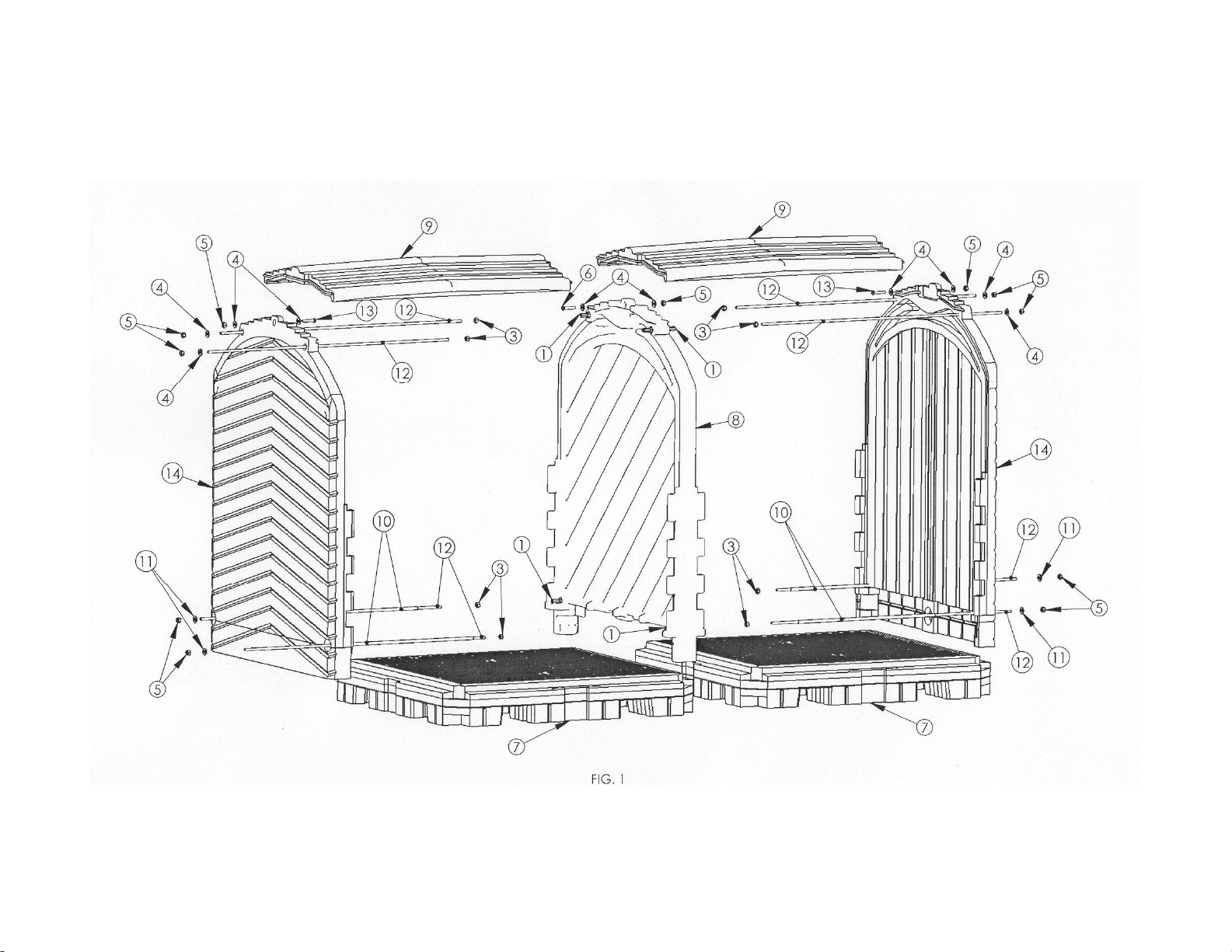
·Please refer to the Figure 1 & 2 and parts list on Pages 4-6.
PAK948 –12 Drum Roll Top Hardcover
This unit comes in two parts
Part 1 is a fully assembled 8 drum unit with an interior wall on one end.
Part 2 is an end wall unit that needs to be assembled to Part 1
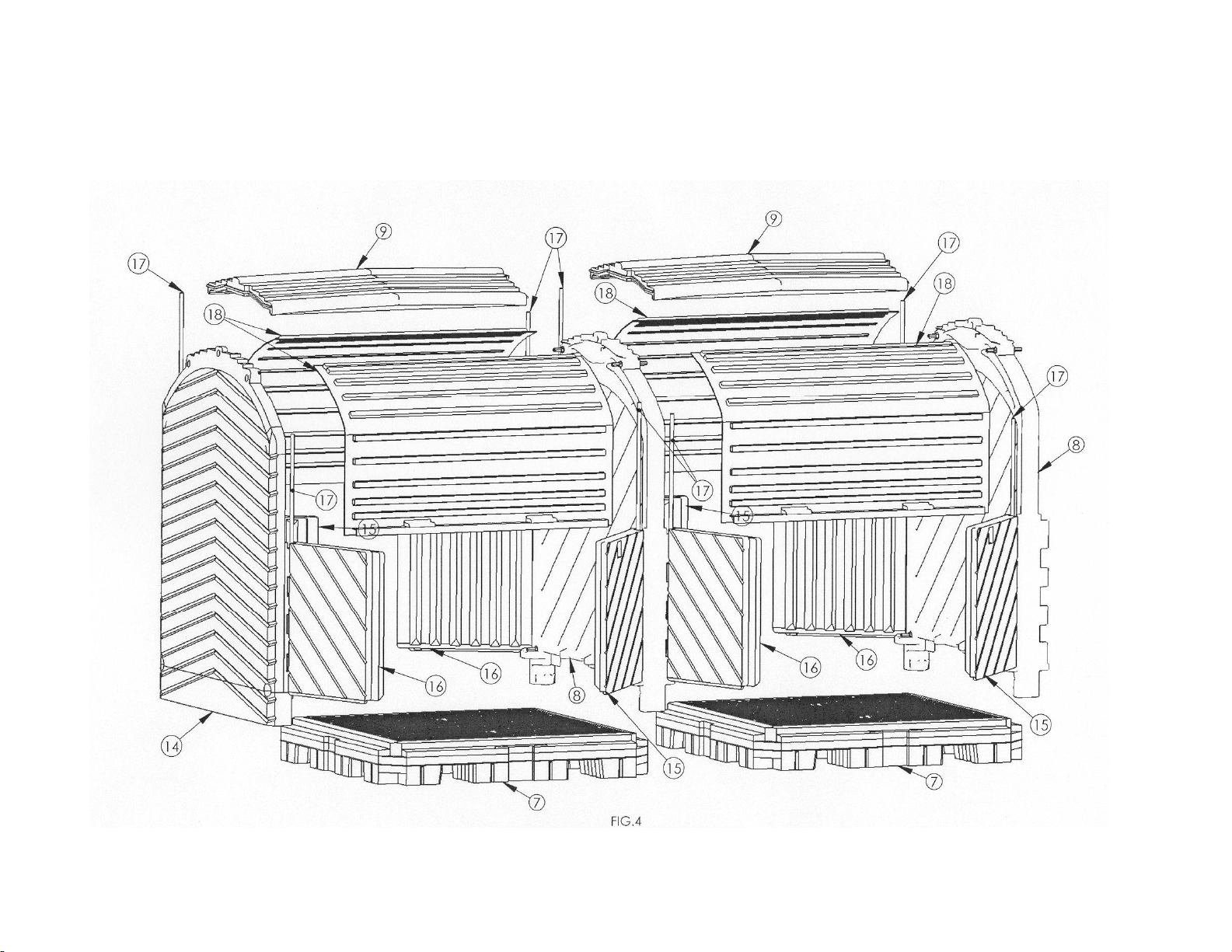
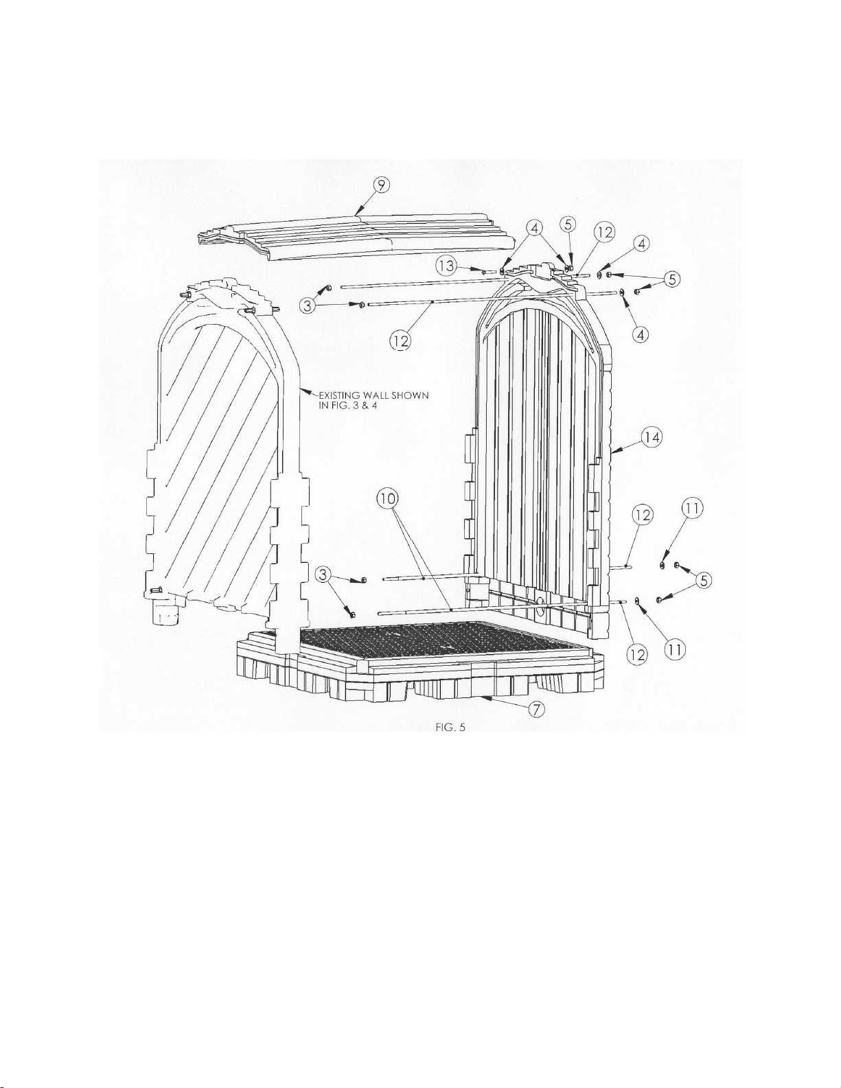
·Please refer to Figures 3,4,5 & 6 and parts list on pages 7-12.
·Follow the assembly instructions starting with Step 13 on page 21
when adding the End Wall unit to complete the assembly.
PAK946 –Add-on Roll Top Hardcover Unit
This unit comes unassembled.
It is used to add on to any 8,12,16,20, etc…existing assembly.
·Please refer to the Figure 7 & 8 and parts list on Pages 13-15.
·Follow the assembly instructions starting with
1) Step 1 on page 16 if assembling an Add-on Roll Top Hardcover
to an existing unit that has already been fully assembled.
*Note: Requires some disassembling first to add on.
2) Step 5 on page 17 if adding an Add on Roll Top Hardcover to a
unit that has an interior wall exposed.

4

5

6
8 Drum Hardware and Parts Assembly List
Figure 1 & 2
Description Qty
*1 Interior Wall Nut Assembly 4
3 3/8”-16UNC Hex Nut 8
4 3/8”Flat Washer 10
5 3/8”-16UNC Nylon Hex Locknut 11
6 3/8”-16UNC x 3”Hex Head Bolt 1
7 4 Drum Heavy Duty Pallet Sump W/Grates 2
8 Interior Wall 1
9 Roof 2
10 Black Plastic Rod Cover 4
11 3/8”x 1-1/2”Flat Washer 4
12 3/8"-16UNC x 59-1/2"L Threaded Rod 8
13 3/8”-16UNC x 2”Hex Head Bolt 2
14 End Wall 2
15 Right Hand Door 4
16 Left Hand Door 4
17 Hinge Pin Tube 8
18 Roll Door 4
*19 ¼”-20UNC x 1-1/4”Allen Head Bolt (Not Shown) 12
*20 ¼”-20UNC Nylon Locknut (Not Shown) 12
*21 ½”EMT Conduit x 56-3/8”Long (Not Shown) 4
22 Black Plastic Caps 10
23 Caulk (if not assembled) 2
*Note: Part 1 is factory installed on the Interior Wall (8).
Parts 19,20&21 are factory installed on the roll door (18).

7

8

9
12 Drum (Part 1) Hardware and Parts Assembly List
Figure 3 & 4
Description Qty
*1 Interior Wall Nut Assembly 8
2 3/8”-16UNC x 56”L Threaded Rod 4
3 3/8”-16UNC Hex Nut 12
4 3/8”Flat Washer 8
5 3/8”-16UNC Nylon Hex Locknut 7
6 3/8”-16UNC x 3”Hex Head Bolt 2
7 4 Drum Heavy Duty Pallet Sump W/Grates 2
8 Interior Wall 2
9 Roof 2
10 Black Plastic Rod Cover 4
11 3/8”x 1-1/2”Flat Washer 2
12 3/8"-16UNC x 59-1/2"L Threaded Rod 4
13 3/8”-16UNC x 2”Hex Head Bolt 1
14 End Wall 1
15 Right Hand Door 4
16 Left Hand Door 4
17 Hinge Pin Tube 8
18 Roll Door 4
*19 ¼”-20UNC x 1-1/4”Allen Head Bolt (Not Shown) 12
*20 ¼”-20UNC Nylon Locknut (Not Shown) 12
*21 ½”EMT Conduit x 56-3/8”Long (Not Shown) 4
22 Black Plastic Caps 5
23 Caulk (if not assembled) 2
*Note: Part 1 is factory installed on the interior wall (8).
Parts 19,20&21 are factory installed on the roll door (18).

10

11

12
12 Drum (Part 2) End Wall Hardware and Parts Assembly List
Figure 5 & 6
Description Qty
3 3/8”-16UNC Hex Nut 4
4 3/8”Flat Washer 4
5 3/8”-16UNC Nylon Hex Locknut 5
7 4 Drum Heavy Duty Pallet Sump W/Grates 1
9 Roof 1
10 Black Plastic Rod Cover 2
11 3/8”x 1-1/2”Flat Washer 2
12 3/8"-16UNC x 59-1/2"L Threaded Rod 4
13 3/8”-16UNC x 2”Hex Head Bolt 1
14 End Wall 1
15 Right Hand Door 2
16 Left Hand Door 2
17 Hinge Pin Tube 4
18 Roll Door 2
*19 ¼”-20UNC x 1-1/4”Allen Head Bolt (Not Shown) 6
*20 ¼”-20UNC Nylon Locknut (Not Shown) 6
*21 ½”EMT Conduit x 56-3/8”Long (Not Shown) 2
22 Black Plastic Caps 5
23 Caulk 2
*Note: Parts 19,20&21 are factory installed on the roll door (18).

13

14

15
Interior Wall Hardware and Parts Assembly List
Figure 7 & 8
Description Qty
*1 Interior Wall Nut Assembly 4
2 3/8”-16UNC x 56”L Threaded Rod 4
3 3/8”-16UNC Hex Nut 8
4 3/8”Flat Washer 2
5 3/8”-16UNC Nylon Hex Locknut 1
6 3/8”-16UNC x 3”Hex Head Bolt 1
7 4 Drum Heavy Duty Pallet Sump W/Grates 1
8 Interior Wall 1
9 Roof 1
10 Black Plastic Rod Cover 2
15 Right Hand Door 2
16 Left Hand Door 2
17 Hinge Pin Tube 4
18 Roll Door 2
*19 ¼”-20UNC x 1-1/4”Allen Head Bolt (Not Shown) 6
*20 ¼”-20UNC Nylon Locknut (Not Shown) 6
*21 ½”EMT Conduit x 56-3/8”Long (Not Shown) 2
23 Caulk 2
*Note: Part 1 is factory installed on the interior wall (8).
Parts 1,19,20&21 are factory installed on the roll door (18).

16
PLEASE READ ASSEMBLY INSTRUCTIONS CARFULLY
Step 1 Remove the roll door (18) by pulling the bottom edges through the notches in the
walls until it comes out the whole way. Repeat for the opposite side. Take a pair
of channel locks or pliers and pull out the hinge pin tube (17) from the hinged
door (15 or 16). Repeat for the other three doors.
Step 2 Remove the top two bolts (6 & 13) that fasten the roof to the walls.
(See Figure 1) Make sure to save this hardware. It will be needed later in the
assembly.

17
Step 3 Loosen the jam nuts (3) on the 4 threaded rods (12) on the inner side of walls on
the unit. Then hold the nut assembly (1) from turning with a 9/16”wrench, while
the outer nuts (5) are taken off. (Note: The threaded rod may come off as well.
The threaded rod must be removed anyways.) Make sure you remove the top 2
nuts/threaded rods first. This will allow the roof to be removed safely. Save
these rods and hardware for Step 14
Step 4 Once the end wall (14) is removed, clean the caulking out of the grooves of both
walls and off the tongues of the roof. Also slide the pallet(7) away from the unit.
Step 5 Install the four threaded rods (2) into the interior wall nut assembly (1) on the
existing interior wall (8), threading them in about ¼”. Make sure the jam nut (3)
is backed off about 1”. The black covered threaded rods with jam nuts (2,3 &10)
go on the bottom.
Note: The jam nuts (3) and black covers (10) should already be on the threaded
rods, if not please install them before attaching the threaded rods (2)

18
Step 6 Slide the pallet (7) back into place. Take the interior wall (8) and place into
position on the pallet. Thread the bottom two interior wall nut assemblies (1)
onto the black covered threaded rods with jam nuts (2,3& 10) about ¼”. Do not
start the top rods at this time.
Step 7 Thoroughly caulk (23) the interior track of the center walls (8) the full length and
depth of the groove that mates with the roof tongue. Caulk as shown in the
photograph.

19
Step 8 Place the roof (9) into the interior wall grooves. Once the roof is into the grooves,
thread the top two interior wall nut assemblies (1) onto the threaded rods (2).
Using a 9/16”wrench, hold the interior wall nut assembly (1) on the interior wall
(8) from turning, while using a 9/16”socket and ratchet on the outside of the other
interior wall. Tighten the unit until the roofline starts to bow. Make sure the roof
tongues are in the grooves of the walls. Repeat for the other interior wall nut
assembly (1). Tighten the four jam nuts (3) to the interior wall nut assemblies (1)
on the top two threaded rods(2).
Step 9 Insert hex head bolt(6) with the washer (4) through the interior wall and roofs.
(Do not insert a hex bolt (6) on the outer interior wall unit, until the next unit is
added on.) Place a 3/8”washer (4) and a locknut (5) on the end of the bolt.
Tighten bolt securely to draw the sidewall and roof together (there should not be a
gap between the roof and sidewall in this area). Wipe off or smooth out any
sealant that may have squeezed out of the seams.

20
Step 10 Place the top edge of the roll top door (18) into the notches of the sidewalls. (The
door may need to be bowed slightly to place the edges into the notches.) Then
push the door up into the track, until the entire door is in the track. Once the roll
door (18) is in the track slide it down to its closed position. Repeat this step for
the opposite side.
Step 11 Align the right door (15) hinge with the mating hinge on the sidewall. Align the
door hinge pin holes with the hinge pin holes in the sidewall. Slide the hinge pin
tube (17) into the aligned holes (Note: It may be necessary to move the door and
tap the hinge pin tube with a hammer until the hinge pin tube is fully seated all the
way through the hinge holes.) Repeat this step for the remaining right door (15)
and to the remaining left doors (16).
This manual suits for next models
2
Popular Storage manuals by other brands

Samsung
Samsung HD080HJ - 80 GB Hard Drive installation guide

Dell
Dell Storage Center SCv2000 owner's manual

Dell
Dell PowerVault 124T Getting started with

Quest Engineering
Quest Engineering DR6300 Getting started

National Semiconductor
National Semiconductor LSE039R2 user manual

IBM
IBM Storwize V7000 Maintenance Guide