manuals.online logo
Brands
  1. Home
  2. •
  3. Brands
  4. •
  5. PIKA
  6. •
  7. Network Hardware
  8. •
  9. PIKA WARP Plus User manual

PIKA WARP Plus User manual

Copyright © 2011 PIKA Technologies – Version 1.2 June 2011
W
ARP Plus
Q
uick Start Guide
The following items are included in the WARP Plus
package. If any parts are missing, please contact
your distributor.
1. WARP Plus Quick Start Guide (this document)
2. WARP appliance
3. Universal power supply (includes country
specific AC power cord)
4. If you ordered the GSM Least Cost Routing
(LCR) or Local and External IP Survivability
feature, one or two GSM modules. Each
module comes with a cable and antenna.
Before you begin:
Ensure that you have the following items:
1. Non-VLAN tagged port on the LAN switch
2. Standard Ethernet cable
3. Optional: Zip tie
4. Optional: 3.5 mm audio jack cables
5. Optional: two Pan head screws for wall
mounting
6. Optional: small Philips-head screwdriver for
installing modules
7. Optional: small pliers for installing modules
Hardware Connections
•Locate the LAN switch associated with the
Hosted PBX services and the IP phones.
•Connect the WARP appliance to any available
Non-VLAN tagged port with a standard
Ethernet cable.
•If required, connect an overhead speaker to the
line out port using a 3.5 mm audio jack cable as
shown below (paging feature only).
•If required, connect a music source to the line
in port using a 3.5 mm audio jack cable as
shown below (Music on Hold feature only).
Module Installation
If you ordered the LCR or IP Survivability feature,
you must install the GSM module and antenna.
Ensure that the appliance is turned off. You must
be grounded with an anti-static wrist strap. Use a
screwdriver to remove the screws on each of the
side panels on the appliance. Remove the top
cover.
Remove the grey panel on the back of the appliance
as shown below. Use a small pair of pliers to lever
the panel at the left and right upper corners. By
hand, push the panel from the front through the
slot into the casing. Rotate the panel up and down
inside the casing to break the lateral tabs. While
rotating the panel, ensure that you do not damage
the casing at the top of the slot.
Before installing the module, remove the screws
from the posts as shown below.
Copyright © 2011 PIKA Technologies – Version 1.2 June 2011
W
ARP Plus
Q
uick Start Guide
If only one module is present, it must be installed
in the rightmost (when viewed from the back) bay.
The black module bay connectors are highlighted in
the following picture. Align the module pins with
the connector and insert the module into the
connector. To secure the module to the base board,
set the module on top of the posts on the base
board and insert the screws through the gold holes
on the module.
NOTE: Screws must be used to secure the
modules to the base board at all times to
provide proper contact for frame grounding.
Setting up GSM
The appliance supports GSM wireless connections
via two-port GSM modules. Each port supports a
single GSM radio and SIM card, which must be
inserted into the corresponding external SIM card
slot. Do not use the slots on the underside of the
module. Both 3.3V and 1.8V SIM cards are
supported and you can insert and remove the SIM
card while the WARP appliance is running. If you
use only one radio, you must use the rightmost
(when viewed from the back) radio and SIM slot.
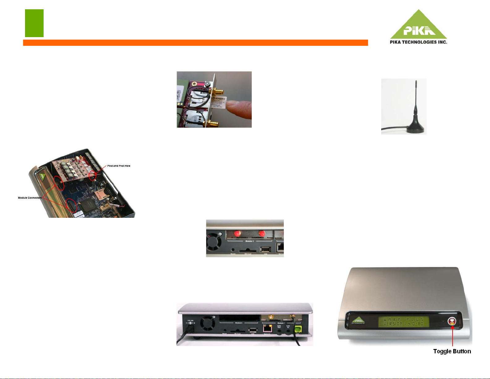
To install a SIM card, slide the card in as shown
until it clicks into place.
To remove it, push inwards until you hear a click
and it will partially eject so that you can completely
remove it from the module.
Each GSM module has two standard SMA
threaded connectors for connecting to external
corded antennas. The GSM module must be
connected to indoor antennas only.
Remove the red dust covers from the antenna
connectors.
Fasten the antenna connector to the connector on
the GSM module. The pin on the antenna cord
must be inserted into the hole of the connector and
the cord must be fully fastened to the connector.
Place the antenna in an unobstructed location as far
away from the appliance as possible. If the
appliance is installed in a cabinet or rack, ensure
that you mount the antenna outside of the rack.
System Startup
The WARP appliance startup sequence takes
approximately two minutes. It is ready to use when
the LCD shows the title screen.
LCD
The LCD has the following screens:
•WARP Plus title screen
•IP address screen
•Error codes screen: The screen should show
ERRORS: None. If not, contact your system
administrator for a list of error codes.
Use the toggle button beside the LCD to switch
between screens.

Other PIKA Network Hardware manuals

PIKA WARP Plus User manual

PIKA

PIKA WARP Plus User manual

PIKA REbus Beacon User manual

PIKA

PIKA REbus Beacon User manual

Popular Network Hardware manuals by other brands

X-Vision X2RN user guide

X-Vision

X-Vision X2RN user guide

Planet GRT-101 user manual

Planet

Planet GRT-101 user manual

Rack Solutions 2Post installation instructions

Rack Solutions

Rack Solutions 2Post installation instructions

Checkpoint 5000 Series Getting started guide

Checkpoint

Checkpoint 5000 Series Getting started guide

Contec LES-RACK Operation manual and installation guide

Contec

Contec LES-RACK Operation manual and installation guide

Checkpoint UTM-1 U-5 Getting started guide

Checkpoint

Checkpoint UTM-1 U-5 Getting started guide

red lion DAS00PN1EE200000 installation guide

red lion

red lion DAS00PN1EE200000 installation guide

Black Box COE-8I manual

Black Box

Black Box COE-8I manual

X-Vision XIP3000NVR user guide

X-Vision

X-Vision XIP3000NVR user guide

Sentryus HD-NVR Series user manual

Sentryus

Sentryus HD-NVR Series user manual

Qlogic Storage Networking (Unified Fabric Pilot) installation guide

Qlogic

Qlogic Storage Networking (Unified Fabric Pilot) installation guide

Black Box SW591C manual

Black Box

Black Box SW591C manual

Tripp Lite N48M Series installation guide

Tripp Lite

Tripp Lite N48M Series installation guide

HIK VISION DS-M5504HNI Series user manual

HIK VISION

HIK VISION DS-M5504HNI Series user manual

Tripp Lite N490-016-STST Specification sheet

Tripp Lite

Tripp Lite N490-016-STST Specification sheet

PULSE+ ExacqVision user manual

PULSE+

PULSE+ ExacqVision user manual

HIK VISION DS-96000NI-M8 Series user manual

HIK VISION

HIK VISION DS-96000NI-M8 Series user manual

HIK VISION DS-7116HQHI-K1 user manual

HIK VISION

HIK VISION DS-7116HQHI-K1 user manual

manuals.online logo
manuals.online logoBrands
  • About & Mission
  • Contact us
  • Privacy Policy
  • Terms and Conditions

Copyright 2025 Manuals.Online. All Rights Reserved.