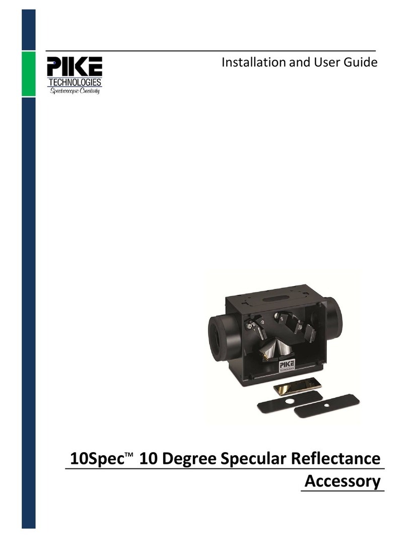
Pike FlexIR Hollow Waveguide User manual

The information in this publication is provided for reference only. All
information contained in this publication is believed to be correct and
complete. PIKE Technologies, Inc. shall not be liable for errors contained herein
nor for incidental or consequential damages in connection with the furnishing,
performance, or use of this material. All product specifications, as well as the
information contained in this publication, are subject to change without notice.
This publication may contain or reference information and products protected
by copyrights or patents and does not convey any license under the patent
rights of PIKE Technologies, Inc. nor the rights of others. PIKE Technologies, Inc.
does not assume any liability arising out of any infringements of patents or
other rights of third parties.
This document contains confidential or proprietary information of PIKE
Technologies, Inc. Neither this document nor the information herein is to be
reproduced, distributed, used or disclosed, either in whole or in part, except as
specifically authorized by PIKE Technologies, Inc.
PIKE Technologies, Inc. makes no warranty of any kind with regard to this
material including, but not limited to, the implied warranties of merchantability
and fitness for a particular purpose.
Copyright 1991-2019 by PIKE Technologies, Inc., Madison, WI 53719. Printed in
the United States of America. All world rights reserved. No part of this
publication may be stored in a retrieval system, transmitted, or reproduced in
any way, including but not limited to, photocopy, photograph, magnetic or
other record, without the prior written permission of PIKE Technologies, Inc.
Address Comments to:
PIKE Technologies, Inc.
6125 Cottonwood Drive
Madison, WI 53719
Phone (608) 274-2721
Fax (608) 274-0103
Web Site www.piketech.com
Jan. 1, 2012

Contents
Introduction
1
Unpacking Your FlexIR HWG Accessory
2
Packing List
2
Installing the FlexIR HWG with MCT Detector
3
Accessory Setup
3
MCT Liquid Nitrogen Filling and Stabilization
3
Installing the HWG Probe
3
Aligning the FlexIR Accessory
4
Optimizing MCT Pre-Amp Gain
6
Removing the FlexIR Accessory
6
Storage
6
ATR Probe
7
Zinc Selenide
7
Germanium
7
Diamond/ZnSe Composite
7
Diffuse Reflectance Probe
8
Specular Reflectance Probe
8
Suggested Measurement Settings
8
Example Applications
9
Precautions
10
SAFETY
10
HGW Probe Assembly Handling
10

PN 350-0453000-02 P a g e | 1
Introduction
The FlexIR Hollow Waveguide Accessory is an excellent tool for remote and specific area analysis of a
wide variety of samples. Visible surface contamination, small area material identification and bulky
materials too large to fit into the FTIR sample compartment are a few of the many samples and
application types for the FlexIR accessory.
The FlexIR Hollow Waveguide (HWG) Accessory is designed for high throughput, ruggedness and wide
spectral range. The FlexIR utilizes a custom optical design with diamond-turned focus optics providing
exceptional IR throughput. The new hollow waveguides are very durable and free from the typical
fracture problems encountered with polycrystalline and glass core fibers. The highly reflective HWG
fibers transmit maximum energy through the mid-IR spectral region eliminating the need for multiple
fibers for a complete spectrum.
Available probes include ATR, diffuse reflectance, and specular reflectance. The ATR probe may be
configured with a zinc selenide, germanium, or diamond/zinc selenide composite crystal. The PIKE
Technologies FlexIR Hollow Waveguide Accessory is built and tested for optimum performance for your
FTIR spectrometer.
Figure 1: Optical Diagram of the MCT FlexIR Accessory
Beam returned
from sample
Integrated MCT Detector
Incoming Beam
HWG Probe

PN 350-0453000-02 P a g e | 2
Unpacking Your FlexIR HWG Accessory
In order for you to quickly verify receipt of your accessory, we have included a packing list. Please
inspect the package carefully. Contact PIKE immediately if any discrepancies are found.
WARNING: The hollow waveguide probes have a limited bend radius of 150 mm. A smaller radius bend
will break the probe.
Packing List
FlexIR Manual
FlexIR Hollow Waveguide Base
HWG Probe or Probes
PN 045-3000
PN 045-30XX
(based upon your order)
Quantity 1
Quantity 1
Probe Attachment Screws
Wrench Set
Purge Tubing Kit
(for Mid-IR FlexIR)
Quantity 1
PN 025-3055
Quantity 2
Quantity 1
Funnel
Reference Cap
(to fill MCT Detector)
(Diffuse and Specular
Probes only)
Quantity 1
Quantity 1

PN 350-0453000-02 P a g e | 3
Installing the FlexIR HWG with MCT Detector
Accessory Setup
Turn off the power to the FTIR spectrometer. Connect the interface detector cable of the HWG
accessory to the detector connector port of the spectrometer. Consult the FTIR manual for additional
information regarding the detector connector port and the proper software settings to select an
external detector.
The base optics of the Mid-IR FlexIR HWG Accessory fits into the sample compartment of the FTIR
spectrometer. The FlexIR HWG Accessory will include the baseplate mount for your FTIR spectrometer.
Place the accessory into the sample compartment of your FTIR and secure any lock-down screws.
MCT Liquid Nitrogen Filling and Stabilization
Fill the MCT detector with liquid nitrogen using the funnel included with the accessory.
WARNING: Wear safety goggles and protective clothing when handling liquid nitrogen. Exposure to
liquid nitrogen will cause severe skin or eye injury.
Pour a small amount of liquid nitrogen into the funnel and wait for it to drain into the Dewar of the
detector. Add additional small amounts of liquid nitrogen until the detector is filled. Allow the detector
to stabilize for about 10 minutes and then top it off with a final amount of liquid nitrogen to completely
fill the liquid nitrogen Dewar. A lit green LED light indicates the Dewar contains liquid nitrogen and is
beginning the detector cooling process or is sufficiently cooled. It is not an indication that the accessory
is necessarily ready for use. Be sure to wait a 10 minute equilibrium time after the Dewar has been
completely filled. Observing a stable interferogram is another indication that the HWG accessory is
ready for measurements. An insufficiently cooled detector will produce a low and unsteady signal. The
red LED light indicates the accessory is not ready for use. If the red LED is illuminated during use check
that the detector Dewar is filled with liquid nitrogen.
Installing the HWG Probe
The next step is to install the HWG probe. Insert the black probe connector end into the base optics and
secure with hex screws provided with the accessory as shown on the following page.

PN 350-0453000-02 P a g e | 4
Aligning the FlexIR Accessory
This accessory has been pre-aligned on the same make as your spectrometer. In most cases, little to no
further alignment is necessary. To assess the need for additional alignment, check the energy when in
the monitor mode of the spectrometer software. When using the specular or diffuse reflection probe,
slide the reference cap over the probe tip before monitoring the energy. No reference cap required for
ATR probes.
The alignment procedure requires that the IR beam pass through the hollow waveguide(s) and return
the beam through the hollow waveguide to reach the detector. Prior to adjusting the mirrors as
explained below a closed loop must be established. In other words, the alignment process for a diffuse
reflectance or a specular reflectance probe requires that the probe tip be positioned gently touching the
diffuse reference disk or a specular mirror embedded in the reference cap included with the probe,
respectively. For an ATR probe, no reference or mirror is required. Simply be sure the ATR crystal surface
is clean.
Open the FTIR bench setup software display to monitor the interferogram signal strength. Please refer
to your FTIR software manual for details of this operation. Reduce the size of the FTIR aperture to
achieve acceptable interferogram signal strength. If your FTIR does not have an aperture, use an IR
beam-limiting screen placed at the right or left side of the FTIR sample compartment to reduce the
energy to an acceptable level.
Optimize the signal by adjusting the input mirror (Figure 3), which directs the IR beam into the hollow
waveguide(s), located below the installed probes. Rotate slowly the screws, positioned on the diagonal,
one at a time while maximizing the signal by monitoring the energy displayed through the FTIR software.
Figure 2: Assembled FlexIR Accessory

PN 350-0453000-02 P a g e | 5
After adjusting the input mirror optimize the position of the output mirror, which redirects the returned
beam into the detector. Adjust the two screws located on the top of the accessory (Figure 3). This mirror
and the resulting focus on the detector is extremely sensitive to small movements of the positioning
screws. A turn of less than a quarter of a complete rotation will drastically change the amount of energy
striking the detector, which may be monitored through the FTIR software.
Figure 3: Locations of mirror alignment ports
Repeat the adjustment of the input and output mirror two to three more times if increases in
performance are observed, to fully optimize the accessory. The positioning of the MCT detector has
been optimized for the specific bench and probe type. In general, the position of the MCT detector does
not require adjustment. In the event different probe types are in use, the position/alignment of the MCT
detector may slightly improve signal performance. Adjust the MCT detector position in the left or right
direction by loosening the screw located on the detector base rigging as shown in Figure 4. After
adjustment, retighten the screw to secure the detector.
Figure 4: Illustration of MCT detector alignment point
Input Mirror
Adjustment Screws
Output Mirror
Adjustment Screws
Detector Positioning Screw

PN 350-0453000-02 P a g e | 6
Optimizing the MCT Pre-Amp Gain
The MCT pre-amp gain has been adjusted at the PIKE manufacturing facility. It most likely will not
require further adjustment. However, adjustments may be required especially if using different probe
types which exhibit large relative energy differences reaching the detector. For example, the gain is set
higher for a diffuse reflectance probe compared to an ATR probe.
Figure 5: Illustration of MCT detector alignment point
The gain should be adjusted to allow 50% of total energy counts or voltage registering on the detector.
To adjust the gain, remove the gain cap from the front of the base optics. Access the gain screw using a
small screwdriver.
Removing the FlexIR Accessory
Turn off the power to the FTIR spectrometer.
WARNING: Do not disconnect the detector cable before turning off the FTIR. Failure to do this may
cause damage to the FTIR and/or FlexIR electronics.
Remove the signal/power cable from the FTIR spectrometer and remove the FlexIR accessory from the
sample compartment.
Storage
Place the FlexIR fiber optic accessory into the plastic bag provided to protect its optics from dust.
Gain Adjustment Screw

PN 350-0453000-02 P a g e | 7
ATR Probe
The ATR probe may be used to measure solids, liquids, and powders. Intimate contact between the
sample and the ATR crystal is required to obtain a quality spectrum. To use, collect a background
spectrum of a clean ATR crystal. Next, place the ATR tip on the sample and exert pressure to obtain good
contact and collect the sample spectrum.
The ATR probe is sealed up to 60 mm beyond the ATR probe tip. Do not submerge the probe into a
liquid deeper than 60 mm. Double score lines are etched on the probe head to indicate the maximum
immersion allowed. Isopropyl alcohol, a mild solvent, is recommended for cleaning the ATR crystal using
a cotton swab.
Zinc Selenide
Zinc Selenide (ZnSe) is a general-purpose ATR material. It has limited use with strong acids and alkalis.
The acceptable pH range is 5 through 9. Additionally, complexing agents such as ammonia and EDTA will
erode its surface because of the formation of complexes. The maximum temperature range for the ZnSe
probe is ambient to 95 °C.
Germanium
Germanium (Ge) has been used extensively in the past as a higher refractive index material for samples
that have a high refractive index such as carbon filled samples. Due to its higher refractive index, spectra
collected with a Ge ATR crystal are weaker in spectral absorbance compared to spectra collected with
ZnSe or diamond/ZnSe composite ATR crystals. The acceptable pH range is from 1 to 14. The maximum
temperature range for the Ge probe is ambient to 95 °C.
Diamond/ZnSe Composite
Diamond is one of the most rugged optical materials. It can be used for the analysis of a wide range of
samples including acids, bases, and oxidizing agents. Diamond is also scratch and abrasion resistant. Its
disadvantage is the intrinsic absorption from approximately 2300 to 1800 cm-1. The maximum
temperature range for the diamond/ZnSe probe is ambient to 60 °C.

PN 350-0453000-02 P a g e | 8
Diffuse Reflectance Probe
The diffuse reflectance probe is suitable for solid samples with diffuse surfaces only. Do not submerge
the diffuse reflectance probe in powders or liquids as the tip is without a protective window and
damage to the probe will result.
In collecting a background spectrum, insert the probe tip into provided reference cap. If probe fits
tightly or cannot bottom out on reference loosen set screw on side and insert probe cap. Tighten set
screw to provide enough drag/friction to hold the reference cap in place, yet allow the cap to be
removed. Next the sample spectrum is collected after positioning the probe either touching or within
0.4 mm from the sample. The probe tip is delicate. Avoid exerting a strong pressure on the tip end. The
maximum temperature for the diffuse reflectance probe is 95 °C.
Specular Reflectance Probe
The specular reflectance probe is ideal for smooth non-diffuse surfaces. In collecting a background
spectrum, insert probe into provided reference cap. If probe fits tightly or cannot bottom out on
reference loosen set screw on side and insert probe cap. Tighten set screw to provide enough
drag/friction to hold the reference cap in place, yet allow the cap to be removed.
Generally, a specular reflectance spectrum is collected by collecting a background spectrum using the
reference cap with an embedded mirror. Next the sample spectrum is collected after positioning the
probe either touching or within 0.4 mm from the sample. The probe tip is delicate. Avoid exerting a
strong pressure on the tip end. Do not submerge the probe tip in a powder or a liquid as this will result
in damage to the probe. The maximum temperature for the specular reflectance probe is 95 °C.
Suggested Measurement Settings
Wavelength Range: 4000 to 700 cm-1 (actual range of HWG Accessory MCT version: 5000 to 700 cm-1)
Velocity: Select appropriate speed for MCT detector for your spectrometer Resolution: 4 to 8 cm-1
Actual measurement parameters will vary based on the experimental conditions and sample material.

PN 350-0453000-02 P a g e | 9
Example Applications
Analysis of Coatings on Intractable by Panels by Diffuse and Specular Reflectance Probes
Spectra of coated metal samples collected with diffuse and specular reflectance FlexIR probes are
illustrated on the following page. Figure 6 shows a spectrum of a coating on a smooth reflective surface
(coating on the outside of a soda can), conducive to specular reflectance measurements. The second
sample featured a painted surface with diffuse reflectance characteristics (Figure 7).
Figure 6: Spectrum of a coated aluminum surface using the specular reflection probe
Figure 7: Spectrum of a painted panel collected using the diffuse reflection probe
5
10
15
20
25
30
35
40
45
50
55
60
65
70
75
%T
100015002000250030003500 Wavenumbers (cm-1)

PN 350-0453000-02 P a g e | 10
Use of ATR HWG Probe to Investigate Defects in Tape
ATR is an ideal probe to investigate defects on adhesive tape. In this example a background was
collected while the ATR probe was clean. The sample spectrum was then collected after adhering the
tape sample to the ATR crystal. The resulting spectrum is shown in Figure 8. Other applications for the
ATR accessory include reaction monitoring, skin analysis, and small spot defects.
Figure 8: Spectrum of transparent tape (adhesive side) collected with the ZnSe ATR probe
Precautions
SAFETY
Caution should be used when handling and using ATR crystals since some of the materials can be
hazardous. Specifically, zinc selenide is a heavy metal material and should be handled with this in mind.
If the crystal is broken or pulverized, the dust may be harmful by inhalation, ingestion, or skin
absorption.
HWG Probe Assembly Handling
Hollow waveguide assemblies are fragile. Do not bend past their minimum bend radius of 150 mm. Do
not expose probes to shock. Do not drop as they may get damaged. Do not flex or stress the probe and
waveguide interface. Use caution when analyzing powder samples with diffuse and specular reflectance
probes. Stay within the prescribed temperature limit for each probe.
0.50
0.55
0.60
0.65
0.70
0.75
0.80
0.85
0.90
0.95
1.00
T
1000200030004000 Wavenumbers (cm-1)

PN 350-0453000-02 P a g e | 11
Regulatory Compliance
RoHS 2.0: 2011/65/EU
The crossed out wheeled bin is a clear
reminder that the product must NOT be
disposed with household waste. It is the
responsibility of the buyer to discard the
product in accordance with Federal,
regional and local environmental
regulations.
This label is located outside
the accessory, on the back
cover.
Table of contents
Other Pike Measuring Instrument manuals