PIL Sensoren GmbH Hainstraße 50 D-63526 Erlensee
Tel: 49 (0)6183 9109-0 Fax: 49 (0)6183 9109-55 E-mail: info@PIL.de
zertifiziert nach DIN EN ISO 9001
Teach in procedure / Einlernvorgang / Procédure de mis en mémoire
Analogue output adjustment
P1 and P2 define the analogue output slope. P1
determines the 0 V position and P2 the 10 V position.
Positive slope: P1 < P2
Negative slope: P2 < P1
Analoge Kennlinie
Mit P1 und P2 wird der Arbeitsbereich der analogen
Kennlinie festgelegt: P1 bestimmt die Position an der
die Kennlinie den Wert OV annimmt, P2 bestimmt
die Position 10 V.
Positive Kennlinie: P1 < P2
Negative Kennlinie: P2 < P1.
Sortie analogique
P1 et P2 définissent les deux limites de la sortie analogique du
capteur. P1correspond à la limite 0V,
Et le point correspond à la limite 10V.
Pour obtenir une pente positive, il faut donc queP1 < P2
Pour obtenir une pente négative il faut donc que P1 > P2
Normal function:
The Echo LED is ON when the echo is received (this
is the alignment LED confirming that the target is
properly aligned). One of the yellow LED is ON,
when object is not between P1 and P2.
Normale Funktion :
Echo LED an, wenn Echo empfangen wird
(Ausrichthilfe). Jeweils eine gelbe LED leuchtet,
wenn sich das Objekt nicht zwischen P1 und P2
befindet.
Fonction en situation normale:
Le LED correspondant a l’ Echo reste allumé si un écho est reçu
par le capteur. Cela permet de vérifier que le capteur est
correctement aligne avec la cible. Un des LED jaunes est allume
si la cible n’est pas entre P1et P2..
Teach In of P1 position (0V output):
Press key around 6 sec. until the LEDs P1 and Echo
LED are blinking simultaneously (blinking rate will
be 2Hz): sensor is now in Teach In mode for P1 (0V):
LED P1 change the blinking to 1Hz and the Echo
LED returns to normal function to show if the
target is properly aligned.
There is a time window of 30 seconds to teach P1
position.
Place target at the right distance P1.
Press key shortly: P1is now programmed.
The sensor returns into normal functionwith the
new value for P1.
Teach In Modus P1 (Position 0V)
Taster ca. 6 sec. Drücken, bis LEDs P1 und Echo
anfangen mit ~2Hz zu blinken: jetzt ist Sensor im
Teach In Modus für P1 Taster loslassen:
LED P1 blinkt mit ~ 1Hz; Echo LED
normale Funktion (Ausrichthilfe)
Innerhalb von 30 sec. muss P1 eingelernt
werden!
Objekt an neue Position P1 bringen
Taster kurz drücken: P1 ist eingelernt.
Sensor arbeitet jetzt in normaler Funktion
mit neuem eingestellten Wert für P1.
Apprentissage de la position P1 (sortie 0V)
Appuyez sur le bouton pendant 6 secondes jusqu'à ce que les
LEDs P1 et Echo clignotent (a une fréquence de 2Hz): le capteur
est en mode ‘programmation pour la limite P1:
Le LED P1 change de clignotement et passe a une cadence de
1Hz; le LED Echo retrousse sa fonction normale d’alignement.
A ce moment, une séquence de 30 secondes commence pour
effectuer la programmation de la position P1
Placer la cible à la position souhaitee.
Appuyez sur le bouton sous peu:
La position P1 est maintenant mémorisée. Le capteur travaille en
fonction normaleavec la nouvelle valeur pour P1.
Teach In of P2 position (10V output)
Press key around 15 seconds until LEDs P2 and Echo
LED start blinking simultaneously (blinking rate will
be 2Hz). It is important to note that before reaching
the P2 teach in mode, P1 LED will be blinking for
few seconds before reaching P2. After 6 seconds the
LEDs P1 and Echo will be blinking, however after an
additional 9 seconds P2 LED and Echo LED will be
blinking with a 2Hz rate. Release key and now the
sensor is in Teach In mode for P2:
The P2 LED will be blinking now at 1Hz rate and
the Echo LED will return to its normal function
(alignment LED)
There is a time window of 30 seconds to do the
programming of P2
Place the target to the position P2
Press key shortly : P2 is programmed and the sensor
returns into normal function with the new value
for P2 in memory.
Teach In Modus P2 (Position 10V)
Taster ca. 15 sec. drücken bis LED P2 und Echo
LED anfangen mit ~2Hz zu blinken.
Nach 6 sec. fangen LED P1 und Echo LED
an zu blinken, nach weiteren 9 sec. blinkt
dann LED P2 und Echo LED mit ~2Hz.
Taster loslassen: jetzt ist Sensor im Tech In
Modus für P2:
LED P2 blinkt mit ~ 1Hz; Echo LED
normale Funktion (Ausrichthilfe).
Innerhalb von 30 sec. muss jetzt P2 eingelernt
werden!
Objekt an neue Position P2 bringen.
Taster kurz drücken: P2 ist eingelernt
Sensor arbeitet jetzt in normaler Funktion
mit neuem eingestellten Wert für P2.
Apprentissage de la position P2 (Sortie 10V)
Appuyez sur le bouton pendant environ 15 secondes jusqu’à ce
que les LEDs P2 et Echo clignotent a une cadence de 2Hz. Après
6 secondes, les LEDs P1 et Echo commenceront à clignotés mais
il faudra attendre 5 secondes supplémentaires pour que les LEDs
P2 et Echo clignotent et atteindre l’apprentissage de la position
P2. A ce moment, il faut libérer le bouton et le capteur est
maintenant en mode programmation P2:
Le LED P2 clignote maintenant a une cadence de 1Hz et le
LED Echo retourne a sa fonction normale de temoin
d’alignement de la cible.
A ce moment, une séquence de 30 secondes commence pour
effectuer la programmation de la position P2.
Placer la cible a la position P2 désirée.
Appuyez sur le bouton sous peu:. P2 est maintenant programmée.
Le capteur est maintenant en fonction normale avec la nouvelle
valeur pour la position P2.
Warranty/Remedy
PIL warrants goods of ist manufacture as being free
of defective materials and faulty workmanship. If
warranted goods are returned to PIL during the period
of coverage, PIL will repair or replace without charge
those items it finds defective. The foregoing is
Buyer’s sole remedy and is in lieu of all other
warranties, expressed or implied, including those
of merchantability and fitness for a particular
purpose.
Specifications may change without notice. The
information we supply is believed to be accurate and
reliable as of this printing. However we assume no
responsibility for its use.
While we provide application assistance personally,
through our literature and the PIL web site, it is up to
the customer to determine the suitability of the
product in the application.
Garantie und Haftungsansprüche
PIL garantiert für seine hergestellten Produkte fehlerfreies
Material und Qualitätsarbeit. Wenn Produkte innerhalb der
Gewährleistungsfrist an PIL zurückgesendet werden,
ersetzt oder repariert PIL kostenlos die Teile, die als
fehlerhaft angesehen werden. Das Vorangegangene gilt
als einzige Entschädigung des Käufers und alle
anderen ausdrücklichen oder stillschweigenden
Garantien einschließlich Qualitäts- und
Sachmängelhaftung.
Änderungen der technischen Daten ohne Vorankündigung
sind vorbehalten. Die von uns bereitgestellten
Informationen halten wir für exakt und zuverlässig, wie bei
dieser Druckschrift. Wir übernehmen jedoch keine Haftung
für deren Anwendung.
Obwohl PIL persönliche und schriftliche Anwendungshilfe
sowie Informationen über die PIL Webseite bietet, ist es
die Entscheidung des Kunden ob das Produkt sich für die
entsprechende Anwendung eignet.
Garantie/ Recours
PIL garantit que les articles de sa fabrication sont
exempts de défaut de pièces et main d’oeuvre. Si les
articles garantis sont retournés à PIL pendant la période
de couverture, PIL réparera ou remplacera gratuitement
ceux qui auront été trouvés défectueux. Ce qui précède
constitue le seul recours de l’acheteur et se substitue
à toutes autres garanties explicites ou implicites, y
compris celles relatives à la commercialisation ou la
compabilité avec une application particulière.
Les caractéristiques techniques peuvent changer sans
préavis. Les informations que nous apportons sont
présumées précises et fiables au moment de la mise sous
presse. Cependant, nous déclinons toute responsabilité
quant à leur utilisation.
Bien que nous apportions notre aide pour les
applications, de façon individuelle, par notre littérature
et par le site web PIL, il incombe au client de
déterminer si le produit convient à l’application.
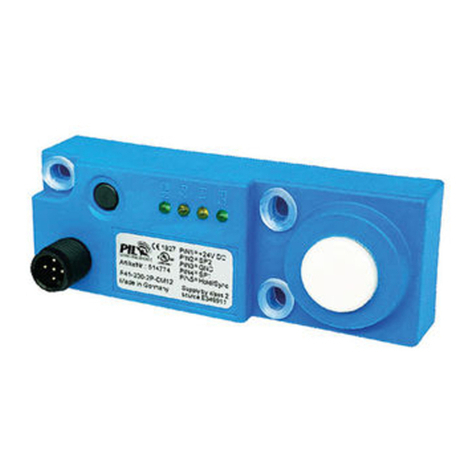
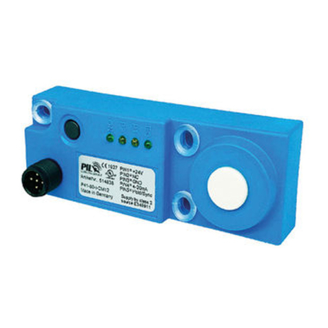
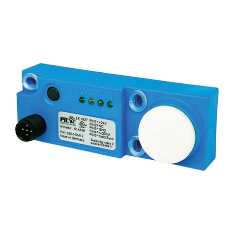
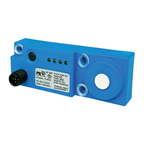
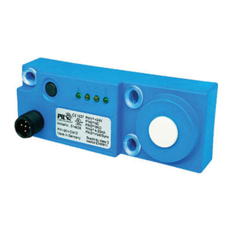
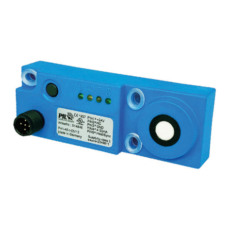
LEDs Echo P1 P2 Power Key / Taster
Supply Bouton
