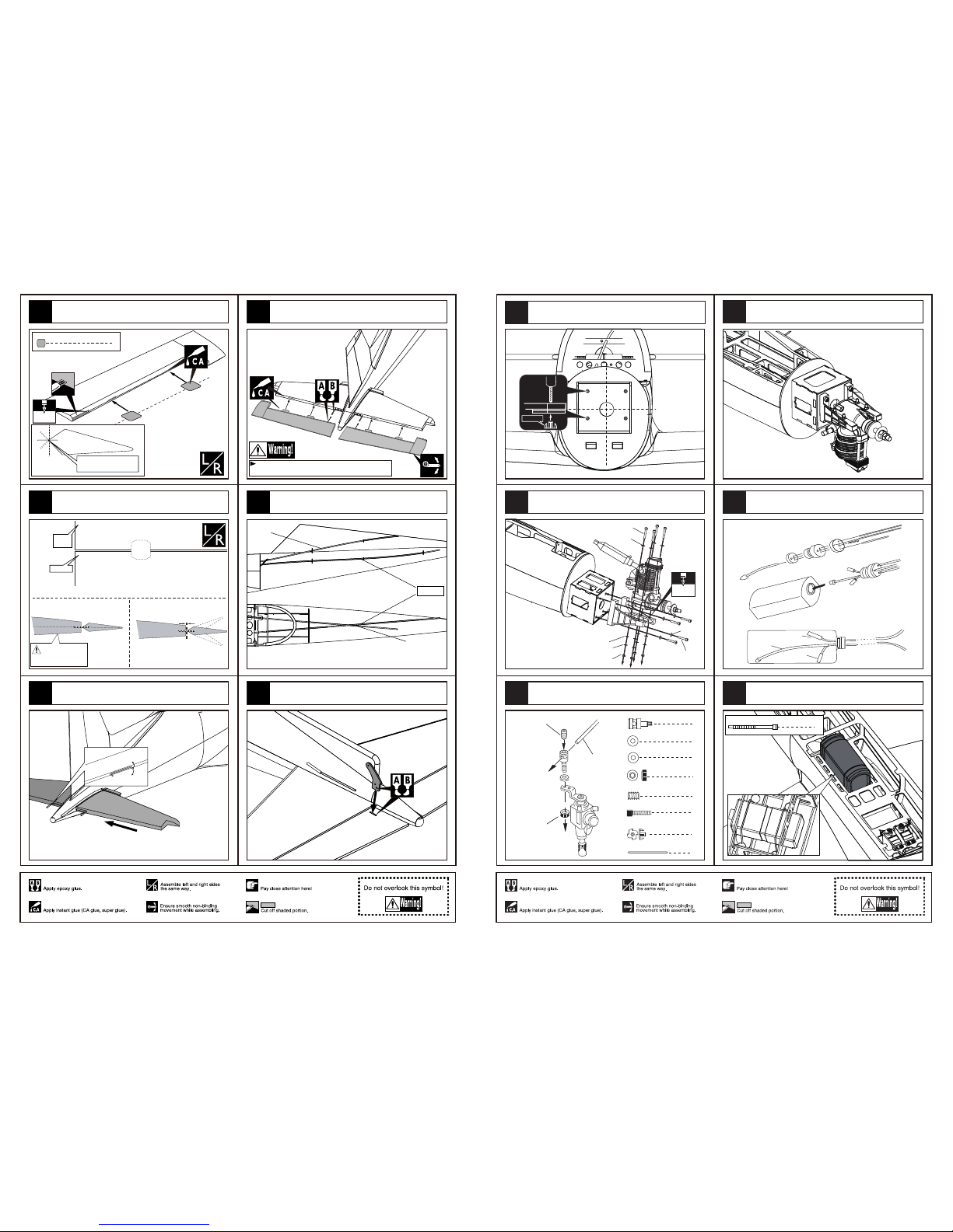
Pilatus PC - 21 User manual

PC - 21
Specification:
Length: 1624mm(64〞)
Wing span: 1397mm(55〞)
Wing area: 34.6sq.dm (3.72sq.ft)
Wing loading: 89.6g/sq.dm(29.4oz/sq.ft)
Flying weight: 3.1kg(6.8lbs)
Radio: 6ch & 6servos
Engine: 4-cycle 52-70
2-cycle 40-52
Motors: 4250 510KV
ESC: 60A
Battery: 6S 2200MAH 20C
Propeller: 14*7
SAFETY PRECAUTIONS
INSTRUCTION MANUAL
First-time builders should seek advice from people having building
experience.If misused or abused,it can cause serious bodily injury
and damage to property.
Fly only in open areas and preferably at a dedicated R/C flying site.
We suggest having a qualified instructor carefully inspect your
airplane before its first flight.Please carefully read and follow all
instructions included with this airplane,your radio control system
and any other components purchased separately.
(The people under 18 years old is forbidden from flying this model)
This R/C airplane is not a toy!
Centre of the Gravity.
Adjustment of the rudder, be sure it can work perfectly.
The side view once the model plane assemble completely.
Adjustment of the elevator,be sure it can work perfectly.
Adjustment of the aileron and flap,be sure they can work
perfectly.
25mm
25mm
AILERON
Side View
30mm
FLAP
AILERON AILERON
Right view
Side View
30mm
30mm
RUDDER
ELEVATOR
Side View
25mm
25mm
Top view
Position for
right diagram.
96mm
71
72
75
73
74
14

4
(with 5 servos),
4
4
4 channel radio for aiplane is highly recommended for this model.
Warning
Remove the covering with proper
pressure to cut through only the covering itself.Otherwise,
cutting down into the balsa structure may weaken the
model part and cause accident.
The pre-covered film on ARF kits may wrinkle due to
variations of temperature.Smooth out as explained right.
Li-Pox4 (2200mAh)
Pre-cover the covering with clean cloth!
Start at low setting. Increase the setting if
necessary.If it is too high,you may damage
the film.
Iow setting
with cover(cloth)
Motor controller:60A
Motor (KV): 600rpm/v
Engine dimension: 42x50mm
Apply epoxy glue.
4-cycle 52-70.
We strongly recommend you use the thread lock for all the screws when you build your model.
14"x7
2 in Spinner
Epoxy the fixed landing gear to the main wing.
Install the nose landing gear servo.
Assemble the nose landing gear to the front gear mount. Assemble the nose landing gear servo to the fuselage.
The sketch map once the model plane assemble completely.
Fix the nose landing gear to fuselage via TP screws.
Collar (4mm)
Collar (4mm)
Collar (4mm)
Linkage Stopper
4
TP Screw (3x12mm)
Linkage Stopper
Washer (2mm)
Washer (2mm)
Nut (2mm)
Set screw (3x4mm)
Washer (
2mm
)
Set screw (3x4mm)
1
1
1
1
13
70
66
68
65
67
79

6
Pin hinge(24x24mm)
Make sure hinges are
mounted in the same line.
1mm
Aileron
Trailing
edge
Make sure they are in
the right position while
installing.
Securely glue together. If coming off during flights, you 'll
lose control of your airplane which leads to accidents!
2
Collar (2mm)
2
2
2
Screw (2x10mm)
Nut (2mm )
2
Washer(2x5mm)
2
Clevis
Servo tray(70x58x2mm)
Control horn
8
6
2
2
Rod (2x300mm)
TP Screw (2.3x12mm)
Pin hinge(24x24mm)
Nut
Washer 2x6mm
Screw 2x10mm
Collar
Install the nylon control horn and connect the linkage.
Assemble the aileron to main wing with instant type
CA glue.
Keep some space about 1mm width between aileron
and trailing edge.
Accessory list for the coming installation steps.
Apply instant type CA glue to aileron and pin hinge. Install the aileron servo to the servo mount as illustration
below.
1
2
3
4
5
1
Trim the cowling along the shaded line.
Epoxy the exhaust to the cowling from lnner.
1.5mm
5
TP Screw (2.3x8mm)
Ply (15x15x3mm) 5
TP Screw (2.3x8mm)
Epoxy the plies under the cowing in fuselage and assemble
the cowing to fuselage with TP screw.
TP Screw (2.3x12mm)
Wooden Block
TP Screw (2.3x12mm)
Collar (4mm)
Collar (4mm)
Wooden supporter
Install the wheel to the fixed landing gear.
Wooden Block
2
8
Collar (4mm)
Wheel (75mm)
Wooden supporter
Landing gear(4mm)
2
1
4
4
TP Screw (3x12mm )
Landing gear straps
1
Plastic mount
4
2
Landing gear (4mm)
1
Wheel (65mm)
16
TP Screw (2.3x12mm)
2
Gear door
16
TP Screw (2.3x12mm)
Landing gear straps 4
Collar 4mm 4
Linkage Stopper 2
1
Rod (2x400mm)
Mount the receiver and the battery in the fuselage.
12
63
62 64
60
61
Accessory list for the coming installation steps.

Apply instant type AB glue to the control horn and the slots in
the aileron, insert the control horn to the slots as illustration.
Make sure to glue securely.
If not properly glued, a failure in flight may occur.
Temporarily fasten down the main wing and
check its correct position.
Securely glue together.If coming off during flights,
you'll lose control of your airplane which leads
to accidents!
A=A'
B=B'
The standard sketch map when the kit install completion.
A
A=A’
B=B’
A’
BB’
Cut away the film on the position for the air retract
landing and epoxy the wheel house to relevant position.
Retracts strut
LockNut(4mm)
Wooden Block
Note:rubber wheels oleo struts
and retracts are optional.
Assemble the gear doors and the wheels to the retracts.
2
Screw (4x35mm)
1
Gear door
2
Wheel (75mm)
2
LockNut (4mm)
2
PVC
1
Reinforcement plate
4
Wooden Block(25x15x13mm)
1
PVC
Main wing joiner 1
TP Screw(3x20mm) 8
2
Washer(4x8mm)
Accessory list for the coming installation steps.
Cut off the surplus PVC part carefully along the shaded
line
6
7
9
8
2
10
Fix the motor mount box to the fuselage with screws.
Washer (4x8mm)
Screw (4x20mm)
Washer (4x8mm)
Screw (4x20mm)
Assemble the motor as below. Epoxy the interior cockpit to the canopy.
Assemble the canopy to the fuselage with screws.
Assemble the Li-Po battery to appropriate position in
the fuselage.
Li-Pox4 (2000mAh)
2
Washer (3x6mm)
2
Screw (3x16mm)
5
TP Screw (2.3x8mm)
Ply (15x15x3mm) 5
2
Exhaust
2
Washer (3x6mm)
2
Screw (3x16mm)
Accessory list for the coming installation steps.
11
59
55
56
57
58

TP Screw (3x20mm)
3mm
TP Screw(3x20mm) 8
Assemble the retract
Securely glue together. If coming off during flights, you 'll
lose control of your airplane which leads to accidents!
Epoxy the main wing hardly together with wing joiner.
Main wing joiner 1
Center
line
145mm
20mm
Drill holes for pulling out the servo extension line.
4mm
2
Screw(4x35mm)
Reinforcement Plate 1
2
Washer(4x8mm)
Mount the wings to the fuselage with screw .
Epoxy the belly pants to the main wing as illustration.
4
Pin hinge(24x24mm)
1
Washer(2x6mm)
Screw (2x10mm)
1
1
Clevis
1
Control horn 1
Rod (1.7x800mm)
1
U-style wire(3x130mm)
Linkage Stopper 1
Accessory list for the coming installation steps.
1
Nut (2mm )
3
14
11
12 15
13
Linkage Stopper
Washer (2mm)
Washer (2mm)
Nut (2mm)
Set screw (3x4mm)
Washer (
2mm
)
Set screw (3x4mm)
1
1
1
1
Install the servo of the throttle.
Assemble the servo in the fuselage.
Mount the receiver and the battery to appropriate position
in the fuselage.
The consumers can also use motors for this plane.please find the
assemble steps below.The front view when the motor install completion.
motor dimension O 42x50mm
The side view when the motor install completion.
110mm
Drill four holes in appropriate position.
4mm
10
54
53
52
50
51
49

4
Pin hinge(24x24mm)
Make sure hinges are
mounted in the same line.
3mm
Apply instant type CA glue to the elevator and trim a
slot in appropriate position in the elevator as illustration.
Elevator
1mm
Trailing
edge
Make sure they are in
the right position while
installing.
Keep some space about 1mm width between the
elevator and horizontal tail edge.
Glue the stabilizer to to fuselage.
Securely glue together. If coming off during flights, you 'll
lose control of your airplane which leads to accidents!
Glue the elevator to the stabilizer by CA and epoxy.
The sketch map of the guide fiber tubes in the fuselage.
Glue the control horn to the slots in the elevator.
Elevator
Rudder
Side view
Top view
Rudder
4
21
20
19
16
18
17
5.2mm
Blind Nut
Set Screw (3x4mm)
Set Screw (2mm)
Rod (2x200mm)
Set Screw (2mm)
Washer (2mm)
Linkage Stopper
1
1
1
1
1
4
4
Washer (4x8mm)
4
Rod (2x400mm)
Blind Nut (4mm)
Screw (4x25mm)
Set Screw (3x4mm)
Assemble the throttle linkage.
Assemble the engine.
Drill four holes at the diameters as shown for engine mount.
Washer (4x8mm)
Washer (4x8mm)
Screw (4x35mm)
Screw (4x20mm)
Nut (4mm)
Spring Washer (4mm)
4mm
Washer (4x8mm)
Fuel supply line
Fuel spray line
Air pressure line
Assembly of the fuel tank.
The sketch map when the engine install completion.
Fix the fuel tank to appropriate position in the fuselage
with cable tie.
cable tie 2
9
48
47
46
44
45
43

Screw (2x10mm)
Nut (2mm)
Washer (2x6mm)
Rod (2x800mm)
Linkage Stopper
Washer (2mm)
Washer (2mm)
Nut (2mm)
Set screw (3x4mm)
Washer (
2mm
)
Set screw (3x4mm)
1
1
1
1
Install the servo of the elevator
Assemble the elevator servo in the fuselage.
Lock the linkage to the control horn with screws and nuts
as below.
Epoxy the fairing sheet to the slots in the fuselage as
illustration.
2
Pin hinge(24x24mm)
1
Washer(2x6mm)
Screw (2x10mm)
1
1
Clevis
1
Control horn 1
Rod (1.7x700mm)
Linkage Stopper 1
Accessory list for the coming installation steps.
Epoxy the vertical fin to the fuselage steadily.
1
Nut (2mm )
5
26
25
22
24
23
2
Steel wire (0.5x900mm)
Assemble the steeling fullarm around the landing gear.
2
2
2
Clevis
Copper joiner
Aluminum tube
2
2
Screw (2x10mm)
Nut (2mm )
2
Washer(2x6mm)
Steel wire
Copper joiner
Aluminum tube Lock Nut (2mm )
Screw (2x10mm)
Clevis
Washer(2x6mm)
Install the servo for the nose gear.
Assemble the nose gear servo to the relevant position in
the fuselage.
110mm
The front view of the engine install completion.
The side view of the engine install completion.
4
Blind Nut (4mm)
1
Engine mount (52x86mm)
Linkage Stopper
4
4
20
4
Washer(4x8mm)
Screw (4x35mm)
Spring Washer (4mm)
Nut (4mm)
2
12
Screw (4x20mm)
2
Plastic tube (2x400mm)
1
Rod (2x200mm)
Fuel tank (260cc) 1
Motor mount box
1
Cable tie 2
Accessory list for the coming installation steps.
8
41
38
40 42
39

2
Pin hinge(24x24mm)
Make sure hinges are
mounted in the same line.
Apply instant type CA glue to aileron and pin hinge. Epoxy the control horns to the slots in the rudder.
Lock the linkage to the control horn with screws and nuts
as below.
rudder
1mm
Trailing
edge
Make sure they are in
the right position while
installing.
Keep some space about 1mm width between the rudder and
tail edge.
Epoxy the rudder to the vertical fin.
Securely glue together. If coming off during flights, you 'll
lose control of your airplane which leads to accidents!
Rod (2x300mm)
Screw (2x10mm)
Nut (2mm)
Washer (2x6mm)
Linkage Stopper
Washer (2mm)
Washer (2mm)
Nut (2mm)
Set screw (3x4mm)
Washer (
2mm
)
Set screw (3x4mm)
1
1
1
1
Install the servo of rudder.
6
32
31
30
27
29
28
Elevator
Rudder
Make sure to glue securely.
If not properly glued, a failure in flight may occur.
Temporarily fasten down the main wing and
check its correct position.
Securely glue together.If coming off during flights,
you'll lose control of your airplane which leads
to accidents!
The standard sketch map when the kit install completion.
A
A ’
A = A ’
B = B ’
BB ’
Collar (5mm) 2
1
Wheel (65 mm)
1
Steering fullarm (50x6mm)
2
Washer(3x6mm)
2
Screw (3x10mm)
1
Aluminum shaft(5x30mm)
Steering fullarm (50x6mm)
Washer(3x6mm)
Screw (3x10mm)
Aluminum shaft(5x30mm)
collar (5mm)
collar (5mm)
Wheel (65 mm)
Aluminum shaft
Screw (3x10mm)
Screw (3x10mm)
Washer(3x6mm)
Washer(3x6mm)
Steering fullarm (50x6mm)
Assemble the nose wheel.
3mm
4
TP Screw (3x20mm) TP Screw (3x20mm)
Install the nose landing gear to appropriate position in
the fuselage.
2
Washer(2x6mm)
Screw (2x10mm) 2
Collar (5mm)
2
1
2
Wheel (65mm)
2
4
Clevis
2
Copper joiner
2
Aluminum tube
1
2
1
Steel wire (0.5x900mm)
TP Screw (3x20mm)
2
2
Nut (2mm )
Accessory list for the coming installation steps.Assemble the rudder servo in the fuselage.
Epoxy the fairing parts to the slots in the fuselage.
7
36
33
35
34
37
Table of contents
Other Pilatus Toy manuals