9 | P a g e Alta-Tec 31-38VS Rev 01 02-01-2020
Safety Regulations
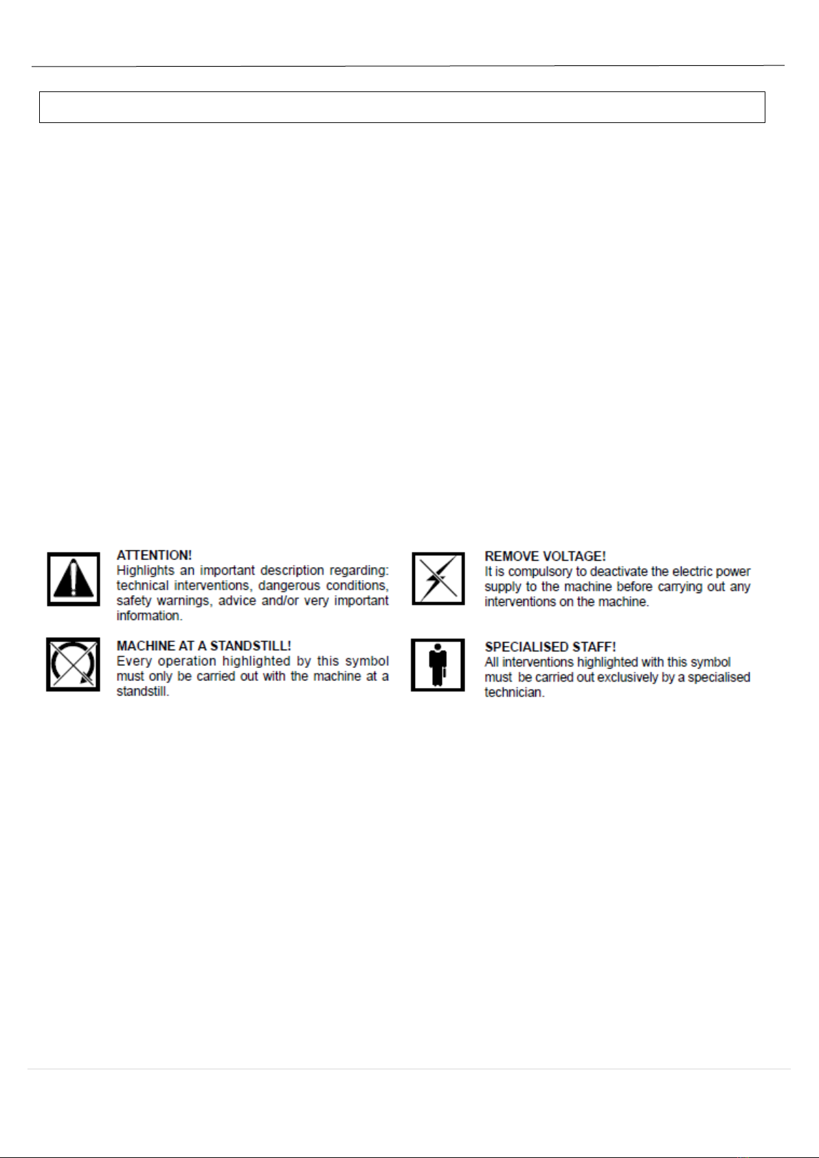
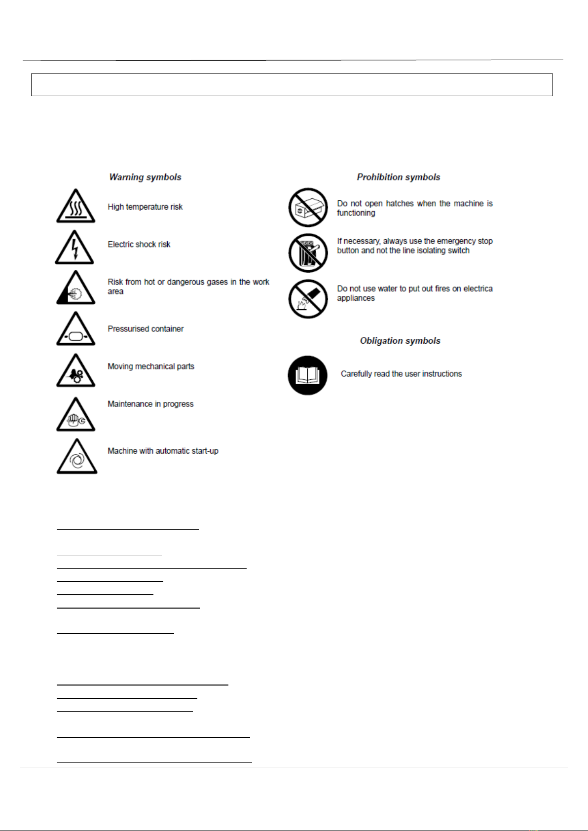
SYMBOLS USED ON THE COMPRESSOR
Several different labels are applied to the compressor. Their function is most of all to highlight any hidden
dangers and to indicate correct behavior during use of the machine or in particular situations.
It is of fundamental importance that they are respected.
TO DO:
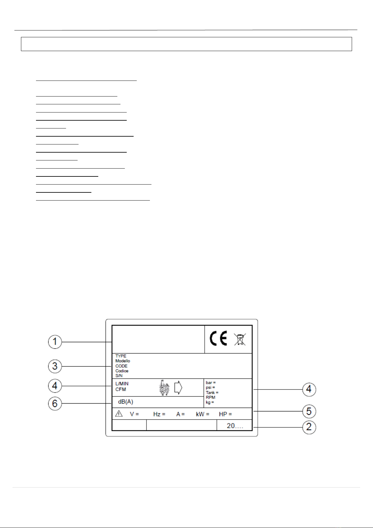
•Make sure that mains voltage corresponds to the voltage indicated on CE plate and that cable of suitable
cross-section are used for electric connections.
•Always check oil level before starting the compressor.
•Be familiar with emergency stop control and all other controls.
•Unplug the connector before any maintenance work, so to avoid accidental start.
•Ensure that all parts have been correctly reassembled after any maintenance work.
•Keep children and animals off the working area to avoid injuries caused by devices connected to the
compressor.
•Ensure that temperature of the working environment ranges between +2 and + 45 ºC. Compressor
working temperature shall range between 70÷85°C (20-25°C room temperature). Lower temperatures
may cause condensate accumulation inside the oil separator tank (inside the compressor).
•Check for condensate and if necessary, drain it (see maintenance).
•The compressor should be installed and operated in a non-explosive environment.
•Allow at least 80 cm between the compressor and the wall so to allow free air flow to the fan.
•Press the emergency button on the control panel only in case of actual need so as to avoid possible
damages to people or the very compressor.
•When calling for technical assistance and/or advice, always mention model, code and serial number
indicated on CE plate.
•Always follow the maintenance schedule specified in the user’s guide.