Pilz PZE X4 User manual

- 1 -
Sicherheitsbestimmungen
• Das Gerät darf nur von Personen installiert
und in Betrieb genommen werden, die mit
dieser Betriebsanleitung und den gelten-
den Vorschriften über Arbeitssicherheit
und Unfallverhütung vertraut sind.
Beachten Sie die VDE- sowie die örtlichen
Vorschriften, insbesondere hinsichtlich der
Schutzmaßnahmen.
• Beim Transport, bei der Lagerung und im
Betrieb die Bedingungen nach EN 60068-
2-6 einhalten (s. technische Daten).
• Durch Öffnen des Gehäuses oder
eigenmächtige Umbauten erlischt die
Gewährleistung.
• Montieren Sie das Gerät in einen Schalt-
schrank; Staub und Feuchtigkeit können
sonst zu Beeinträchtigungen der Funktio-
nen führen.
• Sorgen Sie an allen Ausgangskontakten
bei kapazitiven und induktiven Lasten für
eine ausreichende Schutzbeschaltung.
Safety Regulations
• The unit may only be operated and
installed by personnel who are familiar
with both these instructions and the current
regulations for safety at work and accident
prevention. Follow CEN and local
regulations especially as regards
preventative measures.
• Transport, storage and operating
conditions should all conform to
EN 60068-2-6 (see Technical Data)
• Any guarantee is void following opening
the housing or unauthorised modifications
• The unit should be panel mounted,
otherwise dampness or dust could lead to
a malfunction of the unit
• Adequate protection must be provided on
all output contacts with capacitive and
inductive loads.
Authorised Applications
The contact block PZE X4 is an expander
module for increasing the number of contacts
available in safety circuits. The contact block
PZE X4V has delay off contacts for use in
category 1 Emergency Stop circuits The PZE
X4/X4V are for use in
• Applications with Emergency Stop Relays,
Safety Gate Monitors or Two-Hand
Controls.
• Safety circuits to EN 60947-5-1,
EN 60204-1 and VDE 0113-1.
The unit may only be used with a base unit
that has a feedback control loop (see Fig. 2).
The category to be implemented in
accordance with EN 954-1 depends on the
category of the base module. It cannot be
exceeded by the expander module.
Conseils préliminaires
• La mise en oeuvre de l’appareil doit être
effectuée par une personne spécialisée en
installations électriques, en tenant compte
des prescriptions des différentes normes
applicables (NF, EN, VDE..), notamment
au niveau des risques encourus en cas de
défaillance de l’équipement électrique.
• Respecter les exigences de la norme
EN 60068-2-6 lors du transport, du
stockage et de l’utilisation de l’appareil.
• Toutes interventions sur le boîtier
(ouverture du relais, échange ou
modification de composants, soudure etc..)
faites par l’utilisateur annulent la garantie.
• Montez l’appareil dans une armoire
électrique à l’abri de l’humidité et de la
poussière.
• Assurez-vous du pouvoir de coupure des
contacts de sortie en cas de charges
inductives ou capacitives.
Domaines d’utilisation
Le relais PZE X4 est un bloc d'extension
qui permet d'augmenter le nombre et le
pouvoir de coupure des contacts de
sécurité. La variante PZE X4V est un bloc
d'extension temporisé à la retombée (pour
AU catégorie 1 par ex.).
Le PZE X4/PZE X4V peut être utilisé avec :
• les relais d'arrêt d'urgence, les relais de
surveillance protecteur et les commandes
bimanuelles
• les circuits de sécurité d'après
EN 60947-5-1, EN 60204-1 et
VDE 0113-1.
Le bloc d'extension ne peut être piloté que
par des relais de sécurité ayant une boucle
de retour (voir Fig. 2).
La catégorie à réaliser selon l’EN 954-1
dépend de la catégorie de l’appareil de base.
Elle ne peut pas être dépassée par le bloc
d’extension de contacts.
Description
The contact block is enclosed in a S-95
housing. There is one version available
without delay-on de-energisation (PZE X4)
and 4 versions available each with a fixed
delay-on de-energisation (PZE X4V). All
versions are for 24 VDC operation.
Features:
• Relay outputs: 4 safety contacts (N/O),
positve-guided
• only PZE X4: Safe separation of safety
contacts 13-14, 23-24, 33-34 from input
circuits A1-A2 and feedback loop Y1-Y2
• LED status indication for output relays
• Connection for Feedback Control Loop
• One-channel drive
Be
stimmungsgemäße Verwendung
Der Kontaktblock PZE X4 dient als Erweite-
rungsgerät zur Kontaktverstärkung und Kon-
taktvervielfachung in Sicherheitsstromkreisen.
Der Kontaktblock PZE X4V dient zusätzlich
zum zeitlich verzögerten Weiterschalten
eines NOT-AUS-Befehls in Sicherheits-
stromkreisen.
Das PZE X4/PZE X4V ist bestimmt für den
Einsatz in
• Anwendungsschaltungen mit NOT-AUS-
Schaltgeräten, Schutztürwächtern und
Zweihandbedienungsrelais
•
Sicherheitsstromkreisen nach
EN 60947-5-1, EN 60204-1 und
VDE 0113-1
.
Das Gerät darf nur mit Grundgeräten
verwendet werden, die einen Rückführkreis
besitzen (siehe Fig. 2).
Die zu realisierende Kategorie nach
EN 954-1 ist abhängig von der Kategorie des
Grundgeräts. Sie kann vom Kontakterwei-
terungsblock nicht überschritten werden.
Gerätebeschreibung
Der Kontaktblock ist in einem S-95-Gehäuse
untergebracht. Es steht eine Geräteaus-
führung ohne Rückfallverzögerung (PZE X4)
und 4 Geräteausführungen mit jeweils fester
Rückfallverzögerung (PZE X4V) zur Verfü-
gung. Alle Varianten sind für den Betrieb mit
24 V DC.
Merkmale:
• Relaisausgänge: 4 Sicherheitskontakte
(S), zwangsgeführt
• nur PZE X4: sichere Trennung der
Sicherheitskontakte 13-14, 23-24, 33-34
von den Eingangskreisen A1-A2 und dem
Rückführkreis Y1-Y2
• LEDs als Schaltzustandsanzeige für die
Ausgangsrelais
• Anschluss für Rückführkreis
• einkanalige Ansteuerung
Description de l’appareil
Inséré dans un boîtier S-95 , le bloc
d'extension est disponible en 1 version avec
contacts instantanés (PZE X4) et 4 versions
avec des temporisations de retombée fixes.
Toutes les variantes sont alimentées en
24 VDC.
Particularités :
• Contacts de sortie :
4 contacts de sécurité (F)
• PZE X4 uniquement :
séparation
galvanique entre les contacts de sécurité
13-14, 23-24, 33-34 et les circuits d’entrée
A1-A2 et la boucle de retour
Y1-Y2
• LEDs de visualisation des relais de sortie
• Boucle de retour
• Commande par 1 canal (contat)
19 454-04
PZE X4/PZE X4V
4D Betriebsanleitung
4GB Operating instructions
4F Manuel d'utilisation
4E Instrucciones de uso
4I Istruzioni per l`uso
4NL Gebruiksaan ijzing

- 2 -
A2 13 23 33
14
K2 K1
43
24 34 44
Y1Y2
A1
K2
K1
U
B
*
Die Sicherheitseinrichtung bleibt auch in
folgenden Fällen wirksam:
• Spannungsausfall
• Ausfall eines Bauteils
• Spulendefekt
• Leiterbruch
• Erdschluss
Funktionsbeschreibung
Der Kontaktblock PZE X4/PZE X4V ist ein
Zusatzgerät und dient der Erweiterung eines
Sicherheitsstromkreises ohne/mit Rückfall-
verzögerung. Der Kontaktblock wird von
einem Grund
gerät (z. B. NOT-AUS-Schalt-
gerät) angesteuert
.
Sobald der Eingangskreis vor A1 geschlos-
sen ist und die Versorgungsspannung
anliegt, gehen die beiden Ausgangsrelais in
Arbeitsstellung. Die Sicherheitskontakte 13-
14, 23-24, 33-34 und 43-44 (PZE X4) bzw.
17-18, 27-28, 37-38 und 47-48 (PZE X4V)
schließen. Die LEDs “CH. 1” und “CH. 2”
leuchten.
Wird der Eingangskreis geöffnet, fallen die
Relais K1 und K2 sofort (PZE X4) bzw. nach
Ablauf der Verzögerungszeit zurück (PZE
X4V). Die zwangsgeführten Sicherheits-
kontakte (s. o.) öffnen.
Sicherheitsfunktionen
Der Kontaktblock erweitert einen bestehen-
den Sicherheitsstromkreis. Da die Ausgangs-
relais durch den Rückführkreis des Grund-
gerätes überwacht werden, übertragen sich
die Sicherheitsfunktionen des bestehenden
Stromkreises auf den Kontaktblock. Bei
Erdschluss löst der Fehlerstrom die interne
elektronische Sicherung aus und die
Ausgangsrelais fallen zurück. Die
Erdschlusssicherheit im Rückführkreis ist
vom verwendeten Grundgerät abhängig.
Betriebsart
• Einkanalige Ansteuerung
- ein Eingangskreis wirkt auf beide
Ausgangsrelais
Montage
L’appareil doit être installé dans une armoire
ayant un indice de protection IP54 minimum.
Un élément d’encliquetage sur sa face
arrière permet de le monter sur rail DIN. Lors
du montage, bloquez l’appareil sur un profilé
support vertical (35 mm) à l’aide d’un
élément de maintien comme par ex. un
support ou une équerre terminale.
Description du fonctionnement
Le relais PZE X4/PZE X4V est un bloc
d'extension qui permet d'augmenter le
nombres des contacts de sécurité sans/avec
temporisation à la retombée. Le bloc
d'extension est piloté par un bloc logique de
base (PNOZ par ex.).
Dès que le circuit arrivant sur A1 est fermé
et que la tension d'alimentation est présen-
te, les 2 relais de sortie passent en position
travail. Les contacts de sécurité 13-14, 23-
24, 33-34 et 43-44 (PZE X4) ou 17-18, 27-
28, 37-38 et 47-48 (PZE X4V) se ferment.
Les LEDs "CH.1" et "CH.2" s'allument.
Si le circuit d'entrée est ouvert, les relais K1
et K2 retombent instantanément (PZE X4)
ou après écoulement de la temporisa-
tion (PZE X4V). Les contacts de sécurité
s'ouvrent.
Fig. 1: Schematisches Schaltbild/Wiring diagram/Schéma interne
PZE X4 PZE X4V
Montage
Das Gerät muss in einen Schaltschrank
mit einer Schutzart von mindestens IP54
eingebaut werden. Zur Befestigung auf einer
Normschiene hat das Gerät ein Rastelement
auf der Rückseite. Sichern Sie das Gerät bei
Montage auf einer senkrechten Tragschiene
(35 mm) durch ein Halteelement wie z. B.
Endhalter oder Endwinkel.
The safety function remains effective in the
following cases:
• Power supply failure
• Component failure
• Coil defect in a relay
• Cable break
• Earth fault
Installation
The unit must be installed in a control
cabinet with a minimum protection type of
IP54. The unit has a notch on the back for
DIN rail attachment. If you are installing the
unit on to a vertical DIN rail (35 mm) ensure
that it is mounted securely by using a
retaining bracket or an end angle.
A1 17 27 37
18
K2 K1
47
28 38 48
Y1Y2
A2
K2
K1
UB
C1
C2
Function Description
The contact block is an add-on unit for
expanding safety circuits with or without time
delayed contacts. The contact block is
controlled by a base unit (eg. E-Stop relay).
As soon as the input circuit, at A1, is
connected and the operating voltage is
applied, both relay outputs energise. The
safety contacts 13-14, 23-24, 33-34 and 43-
44 (PZE X4) or 17-18, 27-28, 37-38 and 47-
48 (PZE X4V) close. The LEDs “CH.1” and
“CH.2” illuminate.
When the input circuit is opened, both relays
K1 and K2 de-energise immediately (PZE
X4) or once the delay-on de-energisation
period has elapsed (PZE X4V). The positive-
guided safety contacts (see above) open.
Safety Functions
The contact block provides additional
contacts in a circuit As the output relays are
monitored via the feedback control loop of
the base unit, the safety functions of the relay
are transferred to the contact block.
In the case of earth faults, the fault currents
trigger the electronic fuse and the output
relays de-energise. The earth fault safety in
the feedback control loop is dependent upon
the base unit used.
Operating Mode
• One-channel drive
- one input circuit operates both
channels.
Fonctions de sécurité
Le bloc d'extension permet d'augmenter le
nombre des contacts de sécurité d'un bloc
logique de sécurité. L'auto-contrôle des
relais interne est réalisé à l'aide de la boucle
de retour. Ainsi les contacts du bloc
d'extension ont le même niveau de sécurité
que les contacts du bloc de base. En cas de
mise à la terre, le fusible électronique
interne déclenche pour une intensité. La
détection de la mise à la terre de la boucle
de retour est assurée par l'appareil de base.
Mode de fonctionnement
• Commande par 1 canal
- le circuit d'entrée agit sur les relais
internes (pilotage par 1 contact)
Le relais répond aux exigences de sécurité
suivantes :
• la sécurité est garantie même dans les
cas suivants :
- défaillance tension d’alimentation
- défaillance bobine
- défaut soudure
- défaillance d'un composant
- mise à la terre
*Sichere Trennung nach EN 60947-1, 6 kV
*Safe separation in accordance with EN 60947-1, 6 kV
*Séparation galvanique selon EN 60947-1, 6 kV

- 3 -
Inbetriebnahme
Beachten Sie bei der Inbetriebnahme:
•Vor die Ausgangskontakte eine Siche-
rung (s. technische Daten) schalten, um
das Verschweißen der Kontakte zu
verhindern.
• Berechnung der max. Leitungslänge Imax
am Eingangs- und Rückführkreis:
R
lmax
R
l
/ km
I
max
=
Rlmax = max. Gesamtleitungs-
widerstand (s. technische Daten)
Rl/km = Leitungswiderstand/km
•Keine kleinen Ströme mit Kontakten
schalten, über die zuvor große Ströme
geführt wurden.
• Leitungsmaterial aus Kupferdraht mit einer
Temperaturbeständigkeit von 60/75 °C
verwenden
• Angaben im Kapitel "Technische Daten"
unbedingt einhalten.
Anschluss und Einstellung
• Versorgungsspannung an Klemmen A1 (+)
und A2 (-) anschließen.
• Eingangskreis
Sicherheitskontakt des Grundgerätes an A1
anschließen
• Rückführkreis
Klemmen Y1 und Y2 mit dem Rückführkreis
des Grundgerätes verbinden.
Ablauf
Das Gerät ist eingeschaltet, wenn
• der Sicherheitskontakt vor A1 geschlossen
ist
• die Versorgungsspannung anliegt.
Die LEDs “CH. 1” und “CH. 2” leuchten; die
Sicherheitskontakte 13-14, 23-24, 33-34, 43-
44 (PZE X4) bzw. 17-18, 27-28, 37-38, 47-48
(PZE X4V) sind geschlossen.
Wird der Eingangskreis geöffnet, öffnen die
Sicherheitskontakte (s. o.) sofort (PZE X4)
bzw. zeitlich verzögert (PZE X4V).
Wieder aktivieren
Eingangskreis schließen
Anwendung
Bitte beachten Sie, dass die Sicherheitsfunk-
tionen des bestehenden Stromkreises nur
erhalten bleiben, wenn der Kontaktblock wie
in Fig. 2 gezeigt angeschlossen wird. Es
können nur Grundgeräte mit Rückführkreis
verwendet werden.
Operation
Please note for operation
• To prevent contact welding, a fuse
(see technical details) must be
connected in front of the output
contacts.
• Calculating the max. cable length Imax at
the input circuit and feedback loop:
R
lmax
R
l
/ km
I
max
=
Rlmax = max. overall cable resistance (see
technical details)
Rl/km = cable resistance/km
•Low currents should not be switched
across contacts across which high
currents have previously been
switched.
• Use copper wire that can withstand
temperatures of 60/75°C
• Important details in the section “Technical
Data” should be noted and adhered to.
Connection and Setting
• Connect operating voltage to terminals
A1(+) and A2(-).
• Input circuit
Connect safety contacts of the base unit
to A1
• Feedback control loop
Connect Y1 and Y2 with the feedback
control loop of the base unit.
To operate
The unit is activated when:
• the safety contact connected to A1 is
closed
• the operating voltage is applied
The LEDs “CH.1” and “CH.2” are
illuminated; the safety contacts 13-14, 23-
24, 33-34, 43-44 (PZE X4) or 17-18, 27-28,
37-38, 47-48 (PZE X4V) are closed.
If the input circuit is opened, the safety
contacts (see above) open immediately
(PZE X4) or after the delayed time has
elapsed (PZE X4V).
Reactivation
Close the input circuit.
Mise en oeuvre
Remarques préliminaires :
• Protéger les contacts de sortie par des
fusibles (voir les caractéristiques
techniques) pour éviter leur soudage
• Calcul de la longueur de conducteur Imax
sur le circuit d’entrée et boucle de retour :
R
lmax
R
l
/ km
I
max
=
Rlmax = Résistivité de câblage totale max.
(voir les caractéristiques techniques)
Rl/km = résistance du câble/km
•Ne pas commuter de faibles intensités
par des contacts ayant au préalable
commutés des intensité plus élevées.
• Utiliser des câbles en cuivre supportant
des températures de 60/75°C
• Respecter les données indiquées dans le
chapitre „Caractéristiques techniques“.
Branchement et réglage
• Ramener la tension d'alimentation 24 VDC
sur les bornes A1(+) (par l'intermédiare
d'un contact de l'appareil de base) et
A2 (-).
• Circuit d'entrée
Câbler le contact de l'appareil de base
sur A1
• Boucle de retour
Relier les bornes Y1 et Y2 à la boucle de
retour de l'appareil de base.
Mise en oeuvre
L'appareil est activé si :
• le contact de commande sur A1 est fermé
• la tension d'alimentation 24 VCC est
présente.
Les LEDs "CH.1" et "CH.2" sont allumées;les
contacts de sécurité 13-14, 23-24, 33-34 et
43-44 (PZE X4) ou 17-18, 27-28, 37-38 et
47-48 (PZE X4V) se ferment.
Si le circuit d'entrée est ouvert, les relais K1
et K2 retombent instantanément (PZE X4)
ou après écoulement de la temporisa-
tion (PZE X4V). Les contacts de sécurité
s'ouvrent.
Réarmement
Refermer le circuit d'entrée
Application
Please note that the safety functions of the
existing circuit are only maintained when the
contact block is connected as shown in
Fig. 2. Only base units with the feedback
control loop may be used.
Utilisation
Le niveau de sécurité des contacts des
blocs d'extension n'est garanti que si le
relais est câblé comme représenté dans la
figure ci-dessous (Fig. 2). Seuls des blocs
logiques avec une boucle de retour peuvent
être utilisés.
Fig. 2: PZE X4/X4V -
Anschlussbild
Connection Diagram
Schéma de branchement
Das Gerät nur wie in der folgenden
Abbildung dargestellt anschließen!
UB
0 V
A1 Y1 Y2
A2
PZE X4
PZE X4V
14 Y2 Y113
Grundgerät
Base unit
Appareil de base
Only connect the unit as shown in the
following example
Câbler uniquement le relais comme
indiqué ci-dessous !

- 4 -
Faults - Disturbances
• Short circuit in the input circuit: Supply
voltage fails and the safety contacts are
opened via an electronic fuse. Once the
cause of the fault has been removed and
operating voltage is switched off, the unit
will be ready for operation after
approximately 1 minute.
• Faulty contact functions: In the case of
welded contacts, no further activation is
possible after the input circuit has been
opened.
Test - Sources d'erreur
• Court-circuit dans le circuit d’entrée : La
tension d’alimentation chute et les contacts
de sécurité sont ouverts par un fusible
électronique. Une fois la cause du défaut
éliminée et la tension d’alimentation
coupée, l’appareil est à nouveau prêt à
fonctionner après environ 1 minute.
• défaillance d'un contact : un nouveau
réarmement est impossible en cas de
soudure d'un contact interne après
ouverture du circuit d'entrée.
Fehler - Störungen
• Kurzschluss im Eingangskreis: Die
Versorgungsspannung bricht zusammen
und die Sicherheitskontakte werden über
eine elektronische Sicherung geöffnet.
Nach Wegfall der Störungsursache und
Abschalten der Versorgungsspannung für
ca. 1 Minute ist das Gerät wieder betriebs-
bereit.
• Fehlfunktionen der Kontakte: Bei ver-
schweißten Kontakten ist nach Öffnen des
Eingangskreises keine neue Aktivierung
möglich.
Technische Daten Technical details Caractéristiques techniques
Versorgungsspannung UB/Operating Voltage/Tension d’alimentation
Spannungstoleranz/Voltage Tolerance/Plage de la tension d’alimentation
Leistungsaufnahme bei UB/Power Consumption/Consommation
Restwelligkeit/Residual Ripple/Ondulation résiduelle
Spannung und Strom an/Voltage, Current at //Tension et courant du
Eingangskreis/Input circuit/circuit d’entrée
PZE X4:
Ausgangskontakte nach EN 954-1, Kategorie 4/Output Contacts to EN 954-1, category 4/
Contacts de sortie d'après EN 954-1, catégorie 4
PZE X4V:
Ausgangskontakte nach EN 954-1, Kategorie 3/Output Contacts to EN 954-1, category 3/
Contacts de sortie d'après EN 954-1, catégorie 3
PZE X4:
Gebrauchskategorie nach/Utilization category to/Catégorie d’utilisation d'après
EN 60947-4-1
EN 60947-5-1(DC13: 6 Schaltspiele/Min, 6 cycles/min, 6 manoeuvres/min)
PZE X4V:
Gebrauchskategorie nach/Utilization category to/Catégorie d’utilisation d'après
EN 60947-4-1
EN 60947-5-1(DC13: 6 Schaltspiele/Min, 6 cycles/min, 6 manoeuvres/min)
Kontaktmaterial/Contact material/Matériau contact
PZE X4:
Kontaktabsicherung extern nach/External Contact Fuse Protection/Protection des contacts
EN 60 947-5-1 (IK= 1 KA)
Schmelzsicherung/Blow-out fuse/Fusibles
Sicherungsautomat/Safety cut-out/Dijoncteur
PZE X4V:
Kontaktabsicherung extern nach/External Contact Fuse Protection/Protection des contacts
EN 60 947-5-1 (IK= 1 KA)
Schmelzsicherung/Blow-out fuse/Fusibles
Sicherungsautomat/Safety cut-out/Dijoncteur
Max. Gesamtleitungswiderstand Rlmax Eingangskreise/Max. overall cable resistance Rlmax
input circuits/ Résistance de câblage totale max. Rlmax circuits d'entrée
einkanalig DC/Single-channel DC/Commande par 1 canal DC
Einschaltverzögerung/Switch-on delay/Temps de réarmement
PZE X4
PZE X4V
Rückfallverzögerung /Delay-on De-Energisation /Temps de retombée
PZE X4
PZE X4V
Toleranz/Tolerance/Tolérance PZE X4V
Überbrückung bei Spannungseinbrüchen/Max. supply interruption before
de-energisation/tenue aux micro-coupures
24 V DC
-15 ... +10 %
2,5 W
20 %
24 V DC/95 mA
4 Sicherheitskontakte (S)/4 safety contacts
(N/O)/4 contacts de sécurité (F)
4 Sicherheitskontakte (S), verzögert/4 safety
contacts (N/O), delayed/4 contacts de
sécurité (F), temporisé
AC1: 240 V/0,01 ... 8A/2000 VA
DC1: 24 V/0,01 ... 8 A/200 W
AC15: 230 V/6 A
DC13: 24 V/5 A
AC1: 240 V/0,01 ... 6A/1500 VA
DC1: 24 V/0,01 ... 6 A/150 W
AC15: 230 V/3 A
DC13: 24 V/4 A
AgCuNi+ 0,2 µm Au
10 A flink/quick acting/rapide oder /or/ou
6 A träge/slow acting/normeaux
24 V AC/DC: 6 A
Charakteristik /Characteristic/
Caractéristiques B/C
6 A flink/quick acting/rapide oder /or/ou 4 A
träge/slow acting/normeaux
24 V AC/DC: 4 A
Charakteristik /Characteristic/
Caractéristiques B/C
30 Ohm
typ. 30 ms, max. 50 ms
typ. 55 ms, max. 200 ms
typ. 30 ms, max. 50 ms
typ. 0,50 s
typ. 0,75 s
typ. 1,00 s
typ. 2,00 s
typ. 3,00 s
-50 % / +50 %
20 ms

- 5 -
EN 60947-5-1, EN 61000-6-2
Frequenz/Frequency/Fréquences:10-55 Hz
Amplitude/Amplitude/Amplitude: 0,35 mm
EN 60068-2-78
2
250 V
4 kV
-10 ... + 55 °C
-40 ... + 85 °C
IP54
IP40
IP20
PPO UL 94 V0
ABS UL 94 V0
0,20 ... 4,00 mm2, 24 - 10 AWG
0,20 ... 2,50 mm2, 24 - 14 AWG
0,6 Nm
87 x 22,5 x 121 mm (3.42" x 0.89" x 4.8")
beliebig/any/indifférente
PZE X4: 175 g; PZE X4V: 205 g
EMV/EMC/CEM
Schwingungen nach/Vibration to/Vibrations d'après EN 60068-2-6
Klimabeanspruchung/Climate Suitability/Conditions climatiques
Luft- und Kriechstrecken nach/Airgap Creepage to/Cheminement et claquage d'après EN 60947-1
Verschmutzungsgrad/Pollution degree/Niveau d'encrassement
Bemessungsisolationsspannung/Rated insulation voltage/Tension assignée d’isolement
Bemessungsstoßspannungsfestigkeit/Rated impulse withstand voltage/Tension assignée de
tenue aux chocs
Umgebungstemperatur/Operating Temperature/Température d’utilisation
Lagertemperatur/Storage Temperature/Température de stockage
Schutzart/Protection/Indice de protection
Einbauraum (z. B. Schaltschrank)/Mounting (eg. panel)/Lieu d'implantation (ex. armoire)
Gehäuse/Housing/Boîtier
Klemmenbereich/Terminals/Bornes
Gehäusematerial/housing material/matériau du boîtier
Gehäuse/Housing/Boîtier
Front/front panel/face avant
Max.Querschnitt des Außenleiters (Schraubklemmen)/Max. cable cross section (screw
terminals)/Capacité de raccordement (borniers à vis)
1 Leiter, flexibel/1 core, flexible/1 conducteur souple
2 Leiter gleichen Querschnitts, flexibel mit Aderendhülse, ohne Kunststoffhülse/
2 core, same cross section flexible with crimp connectors, without insulating sleeve/
2 conducteurs de même diamètre souple avec embout, sans chapeau plastique
ohne Aderendhülse oder mit TWIN-Aderendhülse/without crimp connectors or with TWIN
crimp connectors/souple sans embout ou avec embout TWIN
Anzugsdrehmoment für Schraubklemmen/Torque setting for screw terminals/
couple de serrage (borniers à vis)
Abmessungen H x B x T/Dimensions H x W x D/Dimensions (borniers à vis) H x P x L
Einbaulage/Fitting Position/Position de travail
Gewicht/Weight/Poids
Konventioneller thermischer Strom bei gleichzeitiger Belastung mehrerer Kontakte/Conventional thermal current while
loading several contacts/Courant thermique conventionnel en cas de charge sur plusieurs contacts (AC1, DC1)
Anzahl der Kontakte/number of contacts/nombre des contacts 1 2 3 4
PZE X4: Ith 8 A 6 A 5 A 4 A
PZE X4V: Ith 6 A 5 A 4,5 A 4 A
Abmessungen in mm ('')
121 (4.8")
75 (2.95")
87 (3.42")
22,5
(0,89")
Dimensions in mm ('') Dimensions en mm ('')
Es gelten die 2003-01 aktuellen Ausgaben
der Normen.
The version of the standards current at
2003-01 shall apply.
Se référer à la version des normes en vigeur
au 2003-01.

- 6 -
19 454-04-2008-02 Printed in Germany
A Pilz Ges.m.b.H., ✆01 7986263-0, Fax: 01 7986264, E-Mail: [email protected] AUS Pilz Australia, ✆03 95446300, Fax: 03 95446311, E-Mail:
[email protected] B L Pilz Belgium, ✆09 3217570, Fax: 09 3217571, E-Mail: [email protected] BR Pilz do Brasil, ✆11 4337-1241, Fax: 11 4337-1242,
E-Mail: pilz@pilzbr.com.br CH Pilz lndustrieelektronik GmbH, ✆062 88979-30, Fax: 062 88979-40, E-Mail: [email protected] DK Pilz Skandinavien K/S,
✆74436332, Fax: 74436342, E-Mail: [email protected] E Pilz lndustrieelektronik S.L., ✆938497433, Fax: 938497544, E-Mail: [email protected] F Pilz France
Electronic, ✆03 88104000, Fax: 03 88108000, E-Mail: [email protected] FIN Pilz Skandinavien K/S, ✆09 27093700, Fax: 09 27093709, E-Mail:
pilz.f[email protected] GB Pilz Automation Technology, ✆01536 460766, Fax: 01536 460866, E-Mail: [email protected] I Pilz ltalia Srl, ✆031 789511,
Fax: 031 789555, E-Mail: [email protected] IRL Pilz Ireland Industrial Automation, ✆021 4346535, Fax: 021 4804994, E-Mail: [email protected] J Pilz Japan Co.,
Ltd., ✆045 471-2281, Fax: 045 471-2283, E-Mail: [email protected].jp MEX Pilz de Mexico, S. de R.L. de C.V., ✆55 5572 1300, Fax: 55 5572 4194, E-Mail:
[email protected] NL Pilz Nederland, ✆0347 320477, Fax: 0347 320485, E-Mail: inf[email protected] NZ Pilz New Zealand, ✆09- 6345-350, Fax: 09-6345-
352, E-Mail: [email protected] P Pilz Industrieelektronik S.L., ✆229407594, Fax: 229407595, E-Mail: [email protected] PRC Pilz China Representative
Office, ✆021 62494658, Fax: 021 62491300,
ROK Pilz Korea, ✆031 8159541, Fax: 031 8159542, E-Mail: info@pilzkorea.co.kr
SE Pilz Skandinavien K/S, ✆0300 13990, Fax: 0300 30740, E-Mail: [email protected] TR Pilz Elektronik Güvenlik Ürünleri ve Hizmetleri Tic. Ltd. ¸Sti.,
✆0224 2360180, Fax: 0224 2360184, E-Mail: [email protected] USA Pilz Automation Safety L.P., ✆734 354-0272, Fax: 734 354-3355, E-Mail:
www www.pilz.com
D Pilz GmbH & Co. KG, Sichere Automation, Felix-Wankel-Straße 2, 73760 Ostfildern, Deutschland, ✆+49 711 3409-0, Fax: +49 711 3409-133,
E-Mail: [email protected]
Lebensdauer der Ausgangsrelais/Service Life of Output relays/Durée de vie des relais de sortie
PZE X4:
PZE X4V:
10
1
10 100 1000 10000
Nennbetriebstrom (A)
Nominal operating current (A)
Courant coupé (A)
0.1
DC13: 24 V
AC15: 230 V
AC1: 230 V
Schaltspielzahl x 103
Cycles x 103
Nombre e manvres x 103
DC1: 24 V
10
1
100 1000 10000 100000
0.1
DC1: 24 V
AC1: 230 V
DC13: 24 V
AC15: 230 V
Nennbetriebstrom (A)
Nominal operating current (A)
Courant coupé (A)
Schaltspielzahl x 103
Cycles x 103
Nombre e manvres x 103

- 7 -
Prescripciones de seguridad
• El dispositivo tiene que ser instalado y
puesto en funcionamiento exclusivamente
por personas que estén familiarizadas
tanto con estas instrucciones de uso
como con las prescripciones vigentes
relativas a la seguridad en el trabajo y a
la prevención de accidentes. Hay que
observar tanto las prescripciones VDE
como las prescripciones locales,
especialmente en lo que se refiere a las
medidas de protección.
• Durante el transporte, el almacenaje y el
funcionamiento hay que atenerse a las
condiciones conforme a EN 60068-2-6
(ver datos técnicos). Una vez finalizado
su tiempo de vida útil, hay que eliminar el
dispositivo de forma apropiada.
• Toda garantía se pierde en caso de que
se abra la carcasa o se lleven a cabo
remodelaciones por cuenta propia.
• Montar el dispositivo dentro de un
armario de distribución; en caso contrario
es posible que el polvo y la suciedad
puedan afectar el funcionamiento.
• Hay que cuidar de que haya un
conexionado de seguridad suficiente en
todos los contactos de salida con cargas
capacitivas e inductivas.
Campo de aplicación adecuado
El bloque de contactos PZE X4 sirve como
dispositivo de ampliación para el reforza-
miento y la multiplicación de contactos en
circuitos de seguridad.
El bloque de contactos PZE X4V sirve
además para la transmisión retardada de una
orden de parada de emergencia en circuitos
de seguridad.
El PZE X4/PZE X4V está concebido para su
empleo en
• Aplicaciones con dispositivos de parada
de emergencia, supervisores de puertas
protectoras y relés de manejo a dos
manos
• Circuitos de seguridad según EN 60947-
5-1, EN 60204-1 y VDE 0113-1.
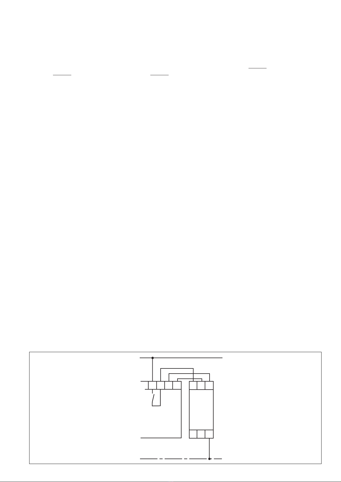
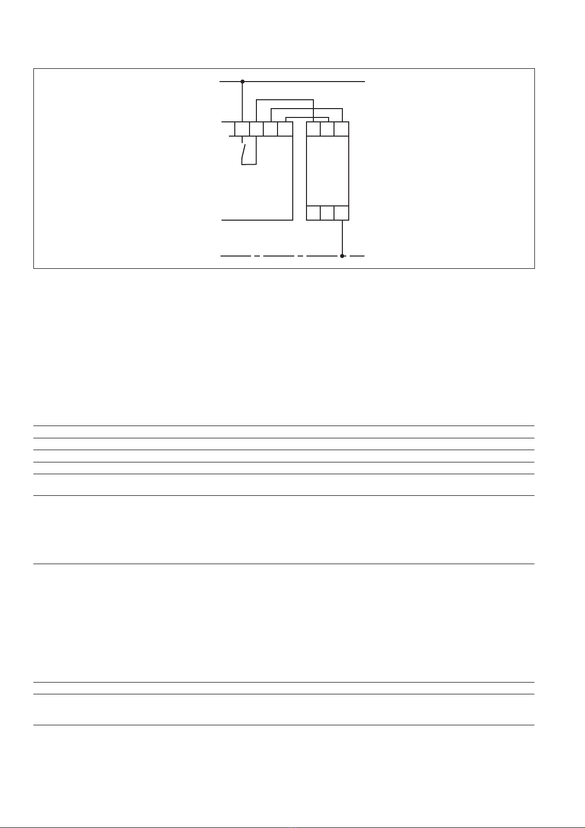
El dispositivo debe utilizarse sólo con
dispositivos base que disponende un circuito
de realimentación (ver fig. 2).
La categoría a realizar según EN 954-1
depende de la categoría del dispositivo base.
No puede superar la categoría del bloque de
ampliación de contactos.
Descripción del dispositivo
El bloque de contactos se encuentra montado
dentro de una carcasa S-95. Se dispone de
un modelo del dispositivo sin retardo a la
desconexión (PZE X4) y de 4 modelos cada
uno de los cuales con retardo a la
desconexión fijo (PZE X4V). Todas las
variantes son para el servicio con 24 V DC.
Norme di sicurezza
• Il dispositivo può venire installato e messo
in funzione solo da persone che
conoscono bene le presenti istruzioni per
l’uso e le disposizioni vigenti relative alla
sicurezza di lavoro e all’antinfortunistica.
Osservare le disposizioni della VDE
(Associazione tedesca degli Ingegneri)
nonché le norme locali, soprattutto per
quanto riguarda le misure preventive di
protezione.
• Durante il trasporto, l’immagazzinamento
e il funzionamento attenersi alle
condizioni prescritte dalla norma EN
60068-2-6 (v. Dati tecnici). Al termine
della propria durata, smaltire il dispositivo
in conformità alle norme vigenti.
• Se viene aperto l’alloggiamento oppure se
vengono apportate delle modifiche in
proprio decade qualsiasi diritto di
garanzia.
• Montare il dispositivo in un armadio
elettrico; altrimenti la polvere e l’umidità
possono pregiudicare le funzioni.
• Occorre dotare tutti i contatti di uscita dei
carichi capacitivi e induttivi con un
cablaggio protettivo sufficiente.
Veiligheidsvoorschriften
• Het apparaat mag uitsluitend worden
geïnstalleerd en in bedrijf genomen door
personen die vertrouwd zijn met deze
gebruiksaanwijzing en met de geldende
voorschriften op het gebied van
arbeidsveiligheid en ongevallenpreventie.
Neem de VDE-voorschriften alsmede de
plaatselijke voorschriften in acht, in het
bijzonder m.b.t. de veiligheidsregels.
• Neem bij transport, opslag en in bedrijf de
richtlijnen volgens EN 60068-2-6 in acht
(zie technische gegevens). Het apparaat
na afloop van zijn levensduur op de juiste
wijze verwijderen en opslaan.
• Het openen van de behuizing of het ei-
gen-machtig aanpassen heeft verlies van
de garantie tot gevolg.
• Monteer het apparaat in een schakelkast.
Stof en vocht kunnen anders de werking
nadelig beïnvloeden.
• Zorg bij alle uitgangscontacten bij capa-
citieve en inductieve belastingen voor
voldoende beschermbedrading.
Uso previsto
Il blocchetto di contatti PZE X4 costituisce un
modulo di estensione per aumentare e
potenziare il numero di contatti disponibili nei
circuiti di sicurezza.
Il blocchetto di contatti PZE X4V serve inoltre
per contatti ritardati degli ordini di Arresto di
Emergenza nei circuiti di sicurezza.
Il PZE X4/PZE X4V è predisposto per
l’impiego in
• Applicazioni con relè per Arresto di Emer-
genza, relè di controllo e relè a comando
bimanuale
•
Circuiti di sicurezza secondo
EN 60947-5-
1, EN 60204-1 e VDE 0113-1.
L’unità può essere solo usata con unità di
base dotate di circuito di retroazione
(vedere Fig. 2).
La categoria da realizzare secondo la norma
EN 954-1dipende dalla categoria del
dispositivo base. Essa non può essere
superata dal modulo di espansione contatti.
Descrizione del dispositivo
Il blocchetto di contatto è inserito in un allog-
giamento P--95. È disponibile una versione
senza ritardo del tempo di scatto (PZE X4) e
4 versioni con ritardo fisso del tempo di scatto
(PZE X4V). Tutte le versioni sono adatte al
funzionamento con 24 V DC.
Gebruik volgens de voorschriften
Het contactblok PZE X4 wordt gebruikt als
uitbreidingsapparaat voor de contactver-
sterking en contactvermeerdering in
veiligheidsstroomcircuits.
Het contactblok wordt bovendien gebruikt voor
het qua tijd vertraagde overschakelen van een
Noodstop-commando in
veiligheidsstroomcircuits. Het PZE X4/PZE
X4V is bedoeld voor het gebruik in
• toepassingsschakelingen in Noodstop-
relais, hekbewakingsschakelaars en
tweehandenbedieningsrelais
• veiligheidsstroomcircuits volgens
EN 60947-5-1, EN 60204-1 en VDE 0113-
1 .
Het apparaat mag uitsluitend met
basisapparaten worden gebruikt, die een
terugkoppelcircuit hebben (zie afb. 2).
De te realiseren categorie volgens EN 954-1
is afhankelijk van de categorie van het
basisrelais. De categorie kan door het
contactuitbreidingsrelais niet overschreden
worden.
19 454-04
PZE X4/PZE X4V
4E Instrucciones de uso
4I Istruzioni per l`uso
4NL Gebruiksaanwijzing
Apparaatbeschrijving
Het contactblok ondergebracht in een S-95-
behuizing. Een uitvoering van het apparaat
zonder afvalvertraging (PZE X4) en 4
uitvoeringen van het apparaat met elk een
vaste afvalvertraging (PZE X4V) zijn
beschikbaar. Alle varianten zijn voor het
gebruik met 24 V DC.

- 8 -
A2 13 23 33
14
K2 K1
43
24 34 44
Y1Y2
A1
K2
K1
U
B
*
Características:
• Salidas de relé: 4 contactos de seguridad
(N.A.), de guía forzosa
• sólo con PZE X4: Separación segura de
los contactos de seguridad 13-14, 23-24,
33-34 de los circuitos de entrada A1-A2 y
del circuito de realimentación Y1-Y2
• LEDs como indicadores del estado de
conmutación para los relés de salida
• Conexión para circuito de realimentación
• Excitación monocanal
La instalación de seguridad permanece activa
aun cuando se presentan los casos
siguientes:
• Corte de la tensión
• Fallo de un elemento constructivo
• Defecto de bobina
• Rotura de línea
• Contacto a tierra
Descripción del funcionamiento
El bloque de contactos PZE X4/PZE X4V es
un dispositivo adicional y sirve para la
ampliación de un circuito de seguridad sin/con
retardo a la desconexión. El bloque de
contactos es controlado por un dispositivo
base (p.ej. un dispositivo de parada de
emergencia).
En cuanto el circuito de entrada delante de A1
está cerrado y se dispone de tensión de
alimentación, los dos relés de salida pasan a
la posición de trabajo. Los contactos de
seguridad 13-14, 23-24, 33-34 y 43-44 (PZE
X4) ó 17-18, 27-28, 37-38 y 47-48 (PZE X4V)
cierran. Los LEDs “CH. 1” y “CH. 2” se
iluminan.
Si se abre el circuito de entrada, entonces se
desactivan los relés K1 y K2 o bien inmedia-
tamente (PZE X4) o bien una vez transcurrido
el tiempo de retardo (PZE X4V). Los
contactos de seguridad de guía forzosa (ver
arriba) se abren.
Funciones de seguridad
El bloque de contactos amplia un circuito de
seguridad ya existente. Dado que los relés de
salida son supervisados por el circuito de
realimentación del dispositivo base, las
funciones de seguridad del circuito existente
se transmiten al bloque de contactos. En caso
de contacto a tierra, la corriente de defecto
dispara el fusible electrónico interno y los
relés se desactivan. La seguridad de contacto
a tierra depende del dispositivo base
empleado.
Fig. 1: Plano de conexiones esquemático / Schema elettrico / Schematisch schakelschema
PZE X4 PZE X4V
A1 17 27 37
18
K2 K1
47
28 38 48
Y1Y2
A2
K2
K1
U
B
C1
C2
Caratteristiche:
• Uscite relè: 4 contatti di sicurezza (NA), a
guida positiva
• solo per PZE X4: separazione sicura dei
contatti di sicurezza 13-14, 23-24, 33-34
dei circuiti di ingresso A1-A2 e del circuito
di retroazione Y1-Y2
• LED per l’indicazione dello stato per i relè
di uscita
• Collegamento per circuito di retroazione
• Comando a canale singolo
La funzione di sicurezza rimane attiva anche
nei casi seguenti:
• Caduta di tensione
• Guasto di un componente
• Difetto della bobina
• Rottura di cavi
• Dispersione a terra
Kenmerken:
• Relaisuitgangen: 4 veiligheidscontacten
(M), mechanisch gedwongen
• uitsluitend bij PZE X4: Veilige scheiding
van de veiligheidscontacten 13-14, 23-24,
33-34 van de ingangscircuits A1-A2 en het
terugkoppelcircuit Y1-Y2.
• LED’s voor weergave van de
schakeltoestand voor de uitgangsrelais
• Aansluiting voor terugkoppelcircuit
• Éénkanaal aansturing
De veiligheidsschakeling blijft ook in de
volgende gevallen werken:
• Spanningsuitval
• Uitval van een component
• Spoeldefect
• Geleiderbreuk
• Aardcontact
Descrizione del funzionamento
Il blocchetto di contatto PZE X4/PZE X4V è
un’unità aggiuntiva e serve all’estensione di
un circuito di sicurezza senza/con ritardo del
tempo di scatto. Il blocchetto di contatto viene
controllatoda un’unità di base (p. es. relè per
arresto di emergenza).
Appena il circuito di entrata su A1 viene
chiuso ed è presente la tensione di
alimentazione, entrambi i relè di uscita
passano in posizione di lavoro. I contatti di
sicurezza 13-14, 23-24, 33-34 e 43-44 (PZE
X4) o 17-18, 27-28, 37-38 e 47-48 (PZE X4V)
si chiudono. I LED “CH. 1” e “CH. 2” si
accendono.
Se il circuito di entrata viene aperto, i relè K1
e K2 si diseccitano immediatamente (PZE X4)
o al termine del tempo di ritardo (PZE X4V).
I contatti di sicurezza a guida positiva (vedere
sopra) si aprono.
Funzioni di sicurezza
Il blocchetto di contatto espande un
determinato circuito di sicurezza. Poiché i relè
di uscita sono controllati tramite il circuito di
retroazione dell’unità di base, essi
trasmettono le funzioni di sicurezza del
circuito elettrico esistente sul blocchetto di
contatto. In caso di dispersione a terrala
corrente di dispersione perde il fusibile
elettronico interno e i relè di uscita si
diseccitano. La sicurezza della dispersione a
terra nel circuito di retroazione dipende
dall’unità di base utilizzata.
Functiebeschrijving
Het contactblok PZE X4/PZE X4V is een aan-
bouwapparaat en wordt gebruikt als uit-
breiding van een veiligheidsstroomcircuit
zonder/met afvalvertraging. Het contactblok
wordt door een basisapparaat (bijv. Noodstop-
relais) aangestuurd.
Zodra het ingangscircuit voor A1 is gesloten
en er voedingsspanning is, gaan de beide uit-
gangsrelais naar de werkpositie. De veilig-
heidscontacten 13-14, 23-24, 33-34 en 43-44
(PZE X4) resp. 17-18, 27-28, 37-38 en 47-48
(PZE X4V) sluiten. De LED’s “CH. 1” en
“CH. 2” branden.
Wanneer het ingangscircuit wordt geopend,
dan vallen de relais K1 en K2 onmiddellijk
(PZE X4) resp. na afloop van de vertra-
gingstijd terug (PZE X4V). De mechanisch
gedwongen veiligheidscontacten (zie boven)
gaan open.
Veiligheidsfuncties
Het contactblok vormt de uitbreiding van een
bestaand veiligheidsstroomcircuit. Aangezien
de uitgangsrelais door het terugkoppelcircuit
van het basisapparaat worden bewaakt, wor-
den de veiligheidsfuncties van het bestaande
stroomcircuit op het contactblok
overgedragen. Bij aardcontact schakelt de
lekstroom de interne elektronische
bescherming uit en de uitgangsrelais vallen
terug. De aardcontactveiligheid in het
terugkoppelcircuit is afhankelijk van het
gebruikte basisapparaat.
*Separación segura conforme a EN60947-1, 6 kV
*Separazione sicura secondo EN60947-1, 6 kV
*Veilige scheiding volgens EN60947-1, 6 kV

- 9 -
Modo de funcionamiento
• Excitación monocanal
- un circuito de entrada actúa sobre
ambos relés de salida
Montaje
El dispositivo tiene que ser montado en un
armario de distribución con un grado de pro-
tección de IP 54 como mínimo. El dispositivo
dispone en su lado trasero de un elemento de
encaje elementos de encaje para la fijación a
una guía normalizada. Al montarlo en una
guía portadora vertical (35 mm) hay que
asegurar el dispositivo por medio de un
elemento de soporte, tal como un soporte o
un ángulo final.
Puesta en marcha
Al poner en marcha hay que tener en cuenta:
•Conectar un fusible antes de los con-
tactos de salida (ver datos técnicos)
con objeto de evitar la soldadura de
los contactos.
• Cálculo de la longitud de línea máxima
Imáx en circuito de entrada y de
realimentación:
Rlmáx = resistencia total de línea máxima
(ver datos técnicos)
Rl/km = resistencia de línea/km
•No conectar corrientes pequeñas con
contactos a través de los cuales se
han conducido anteriormente grandes
corrientes.
• Utilizar para las líneas material de
alambre de cobre con una resistencia a la
temperatura de 60/75 °C.
• Respetar sin falta las indicaciones del
capítulo “Datos técnicos”.
Conexión y configuración
• Conectar tensión de alimentación en los
bornes A1 (+) y A2 (-).
• Circuito de entrada
Conectar a A1 el contacto de seguridad
del dispositivo base.
• Circuito de realimentación
Conectar bornes Y1 y Y2 con el circuito
de realimentación del dispositivo base.
Secuencia
El dispositivo está conectado cuando
• el contacto de seguridad está cerrado
delante de A1
• se dispone de tensión de alimentación.
Los LEDs “CH. 1” y “CH. 2” se iluminan; los
contactos de seguridad 13-14, 23-24, 33-34,
43-44 (PZE X4) o bien 17-18, 27-28, 37-38,
47-48 (PZE X4V) están cerrados.
Si se abre el circuito de entrada, entonces se
abren los contactos de seguridad (ver arriba)
o bien inmediatamente (PZE X4) o bien con
retardo temporal (PZE X4V).
Activar de nuevo
Cerrar el circuito de entrada
Aplicación
Por favor observar que las funciones de segu-
ridad del circuito existente sólo se mantienen
en caso de que el bloque de contactos se
haya conectado como se muestra en la figura
2. Sólo es posible utilizar dispositivos base
con circuito de realimentación.
Modi operativi:
• comando a canale singolo
- un circuito di entrata agisce su entrambi
i relè di uscita
Montaggio
L’unità deve venire montata in un armadio
elettrico con un grado di protezione di almeno
IP 54. Per il fissaggio su di una barra DIN
l’unità è dotata di un rilievo sul retro.
Al montaggio fissare il dispositivo su una
guida verticale (35 mm) a mezzo di supporti
quali p. es. staffe di fissaggio o angoli
terminali.
Bedrijfsmodus
• Éénkanaal aansturing
- een ingangscircuit werkt op beide
uitgangsrelais
Montage
Het apparaat moet in een schakelkast met een
veiligheidsklasse van minstens IP 54 worden
ingebouwd. Voor de bevestiging op een DIN-
rail heeft het apparaat aan de achterzijde een
inklikelement.
Messa in funzione
Alla messa in funzione occorre:
•Per evitare la saldatura dei contatti,
collegare un fusibile (v. Dati tecnici)
prima dei contatti di uscita.
• Calcolo della massima lunghezza di
conduzione Imax sui circuiti d’ingresso e di
retroazione:
Rlmax = mass. resistenza del cavo totale
(vedi Dati tecnici)
Rl/km = resistenza del cavo/km
•Non commutare piccole potenze con
contatti attraverso i quali sono state
commutate in precedenza alte potenze.
• Per i cavi utilizzare materiale in filo di
rame con una resistenza termica intorno
ai 60/75 °C.
• Attenersi assolutamente alle indicazioni
riportate al capitolo “Dati tecnici”.
Connessione e regolazione
• Collegare la tensione di alimentazione ai
morsetti A1 (+) e A2 (-).
• Circuito di entrata
Collegare il contatto di sicurezza dell’unità
di base ad A1.
• Circuito di retroazione
Collegare Y1 e Y2 con il circuito di
retroazione dell’unità di base.
Procedura
Il dispositivo è attivato quando:
• il contatto di sicurezza su A1 è chiuso
• la tensione di alimentazione è presente.
I LED “CH. 1” e “CH. 2” si accendono; i
contatti di sicurezza 13-14, 23-24, 33-34, 43-
44 (PZE X4) o 17-18, 27-28, 37-38, 47-48
(PZE X4V) sono chiusi.
Se il circuito di entrata viene aperto, i contatti
di sicurezza si aprono immediatamente
(vedere sopra) (PZE X4) o con ritardo (PZE
X4V).
Riattivazione
Chiudere il circuito di entrata
Utilizzo
Le funzioni di sicurezza dei circuiti elettrici
esistenti vengono mantenute solo quando il
blocchetto di contatto viene collegato come
illustrato alla fig. 2. Possono essere utilizzate
solo unità di base con circuito di retroazione.
Bij montage op een verticale draagrail
(35 mm) moet het apparaat worden vast-
gezet met een eindsteun zoals bijv.
eindhouder of eindhoek.
Ingebruikname
Neem bij ingebruikname het volgende in acht:
•Sluit voor de uitgangscontacten een
zekering (zie technische gegevens) aan
om het verbinden van de contacten te
verhinderen.
• Berekening van de max. kabellengte Imax
op het ingangs- en terugkoppelcircuit:
R
lmax
R
l
/ km
I
max
=
Rlmax = max. weerstand totale kabel
(zie technische gegevens)
Rl/km = kabelweerstand/km
•Sluit geen kleine stromen op contacten
aan die eerst voor het geleiden van
grote stromen werden gebruikt.
• Leidingmateriaal van koperdraad met een
temperatuurbestendigheid van 60/75 °C
gebruiken.
• Neem de gegevens in het hoofdstuk
“Technische gegevens” in acht.
Aansluiting en instelling
• Voedingsspanning op de klemmen A1 (+)
en A2 (-) aansluiten.
• Ingangscircuit
Sluit het veiligheidscontact van het
basisapparaat op A1 aan.
• Terugkoppelcircuit
Verbind de klemmen Y1 en Y2 met het
terugkoppelcircuit van het basisapparaat.
Verloop:
Het apparaat is ingeschakeld als
• het veiligheidscontact voor A1 gesloten is
• er verzorgingsspanning is.
De LED’s “CH. 1” en “CH. 2” branden; de vei-
ligheidscontacten 13-14, 23-24, 33-34, 43-44
(PZE X4) resp. 17-18, 27-28, 37-38, 47-48
(PZE X4V) zijn gesloten.
Wanneer het ingangscircuit wordt geopend,
dan gaan de veiligheidscontacten (zie boven)
onmiddellijk open resp. worden deze tijdelijk
vertraagd (PZE X4V).
Weer activeren
Ingangscircuit sluiten
Toepassing
U dient ervoor te zorgen dat de veiligheids-
functies van het bestaande stroomcircuit
slechts behouden blijven, wanneer het
contactblok, zoals in afb. 2 is weergegeven,
wordt aangesloten. Uitsluitend basisapparaten
met terugkoppelcircuit gebruiken.
R
lmax
R
l
/ km
I
max
=
R
lmax
R
l
/ km
I
max
=

- 10 -
Tensión de alimentación UB/Tensione di alimentazione UB/Voedingsspanning UB
Tolerancia de tensión de alimentación UB/Tolleranza di tensione UB/Spanningstolerantie UB
Consumo de energía con UB/Potenza assorbita UB/Capaciteitsopname bij UB
Ondulación residual UB/Ondulazione residua UB/Restrimpel UB
Tensión y corriente en el circuito de entrada/Tensione e corrente su circuito d’ingresso/
Spanning en stroom op Ingangscircuit
PZE X4
Contactos de salida de uso según EN 954-1, categoría 4/Contatti di uscita d’uso secondo
EN 954-1, categorie 4/Uitgangscontacten volgens EN 954-1, categorie 4
PZE X4V
Contactos de salida de uso según EN 954-1, categoría 3/Contatti di uscita d’uso secondo
EN 954-1, categorie 3/Uitgangscontacten volgens EN 954-1, categorie 3
PZE X4:
Categóría de uso según/categorie d’uso secondo/Gebruikscategorie volgens
EN 60947-4-1
EN 60947-5-1 (DC 13: 6 ciclos/min)
PZE X4V:
Categóría de uso según/categorie d’uso secondo/Gebruikscategorie volgens
EN 60947-4-1
EN 60947-5-1 (DC 13: 6 ciclos/min)
Material de los contactos/Materiale di contatto/Contactmateriaal
Resistencia de línea total máx. Rlmax circuitos de entrada/Mass. resistenza cavo totale
Rlmax circuiti d’ingresso/Max. weerstand totale kabel Rlmax ingangscircuits
monocanal DC/canale singolo DC/eenkanalig DC
Errores - Fallos
• Cortocircuito en el circuito de entrada: La
tensión de alimentación cae y los
contactos de seguridad se abren a través
de un fusible electrónico. Una vez haya
desaparecido la causa del error y se haya
desconectado la tensión de alimentación
durante aprox. 1 minuto, el dispositivo
volverá a estar listo para el servicio.
• Funcionamientos defectuoso de los con-
tactos: en caso de contactos fundidos,
después de abrir el circuito de entrada no
es posible ninguna nueva activación.
24 V DC
-15 ... +10 %
2,5 W
DC: 20 %
24 V DC, 95 mA
4 contactos de seguridad (N.A.)/4 contatti di
sicurezza (NA)/4 veiligheidscontacten (M)
4 contactos de seguridad (N.A.),
Con retardo
/4 contatti di sicurezza (NA),
Ritardati
/
4 veiligheidscontacten (M),
Vertraagd
AC1: 240 V/0,1 ... 8 A/2000 VA
DC1: 24 V/0,1 ... 8 A/200 W
AC15: 230 V/6 A
DC13: 24 V/5 A
AC1: 240 V/0,1 ... 6 A/1500 VA
DC1: 24 V/0,1 ... 6 A/150 W
AC15: 230 V/3 A
DC13: 24 V/4 A
AgCuNi + 0,2 µm Au
30 Ohm
Datos técnicos / Dati tecnici / Technische gegevens
Fig. 2: PZE X4/X4V -
Plano de conexión /
Schema delle connessioni /
Aansluitschema
UB
0 V
A1 Y1 Y2
A2
PZE X4
PZE X4V
14 Y2 Y113
Dispositivo base
Unit di base
Basisapparaat
Errori - Disturbi
• Cortocircuito nel circuito d’ingresso:
Un fusibile elettronico interrompe
l’alimentazione ed i contatti di sicurezza si
aprono. Una volta rimosso la causa del
gausto e interrotto la tensione di
alimentazione, il dispositivo sarà pronto al
funzionamento dopo circa un minuto.
• Funzionamento errato dei contatti: in caso
di saldatura dei contatti, dopo l’apertura
dei circuiti di entrata non è possibile
nessuna nuova attivazione.
Fouten - Storingen
• Kortsluiting in het ingangscircuit: De
voedingsspanning valt uit en de
veiligheidscontacten worden via een elek-
tronische zekering geopend. Na het
wegvallen van de storingsoorzaak en het
uitschakelen van de bedrijfsspanning voor
ca. 1 minuut is het apparaat weer
bedrijfsklaar.
• Storingen van de contacten: Wanneer
contacten met elkaar zijn verbonden is na
het openen van de ingangscircuits geen
activering mogelijk.
¡Conectar el aparato sólo como se
representa en la figura siguiente!
(ver página siguiente)
Collegare l’unità solo come indicato nella
figura!
(vedere pagina successiva)
Het apparaat uitsluitend, zoals in onder-
staande afbeelding is weergegeven,
aansluiten! (zie volgende pagina)

- 11 -
PZE X4:
Protección externa de los contactos según/Protezione contatti esterna/Contactafzekering extern
volgens EN 60947-5-1 (IK= 1 KA)
Fusible/Fusibile/Smeltzekering
Fusible automático/Interruttore automatico/Zekeringautomaat
PZE X4V:
Protección externa de los contactos según/Protezione contatti esterna/Contactafzekering extern
volgens EN 60947-5-1 (IK= 1 KA)
Fusible/Fusibile/Smeltzekering
Fusible automático/Interruttore automatico/Zekeringautomaat
Retardo a la conexión/
Ritardo all’eccitazione
/Opkomvertraging
PZE X4
PZE X4V
Retardo a la desconexión/Ritardo tempo di scatto/Afvalvertraging
PZE X4
PZE X4V
Tolerancia/Tolleranza/Tolerantie PZE X4V
Inmunidad a cortes de tensión/Ininfluenza mancanza tensione/Maximale spanningsonderbreking
CEM/Compatibilità elettromagnetica/EMC
Oscilaciones según/Vibrazioni secondo norma/Trillingen volgens EN 60068-2-6
Condiciones ambientales/Sollecitazione climatica/Klimaatcondities
Dist. fuga y dispersión superficial según/Intraferri d’aria, vie di dispersione secondo/Lucht- en
kruipwegen volgens EN 60947-1
Grado de suciedad/Grado di contaminazione/Vervuilingsgraad
Tensión de aislamiento de dimensionado/Tensione nominale di isolamento/Nominale
isolatiespanning
Resistencia tensión transitoria de dimensionado/Tensione di tenuta agli urti/Nominale
stootspanningbestendigheid
Temperatura ambiente/Temperatura ambiente/Omgevingstemperatuur
Temperatura de almacenaje/Temperatura di magazzinaggio/Opslagtemperatuur
Grados de protección/Tipi di protezione/Veiligheidsklassen
Lugar de montaje (p.ej. armario de distribución)/Spazio di montaggio (p.es. quadro
elettrico ad armadio)/Inbouwruimte (bijv. schakelkast)
Carcasa/Alloggiamento/Kast
Zona de bornes/Terminali/Aansluitklemmen
Material de la carcasa/Materiale della custodia/ehuizingsmateriaal
Carcasa/Custodia/Behuizing
Frente/Fronte/Front
Sección máx. del conductor externo (bornes de tornillo)/Sezione max del cavo esterno
(morsetti a vite) Max. doorsnede van de aansluitkabels (schroefklemmen)
1 conductor flexible/1 conduttore flessibile/1 draad, flexibel
2 conductores de la misma sección, flexible con terminal: sin revestimiento de plástico/
2 conduttori con lo stesso diametro, flessibile con capocorda senza manicotto in plastica/
2 draden met dezelfde doorsnede, Flexibel met adereindhuls zonder kunststofhuls
flexible sin terminal o con terminal TWIN/flessibile senza capocorda o con capocordaTWIN/
Flexibel zonder adereindhuls of met TWIN-adereindhuls
Par de apriete para bornes de conexión (tornillos)/Coppia di serraggio per i morsetti (viti)/
Aanhaalmoment voor aansluitklemmen (schroeven)
Dimensiones (Al x An x La)/Misure (altezza x largh. x profondità)/Afmetingen H x B x D
Posición de montaje/Posizione di montaggio/Inbouwpositie
Peso/Peso/Gewicht
10 A de acción rápida/rapido/snel o/o/of
6 A de acción lenta/ritardato/trag
24 V AC/DC: 6 A
Característica/Caratteristica/Karakteristiek
B/C
6 A de acción rápida/rapido/snel o/o/of
4 A de acción lenta/ritardato/trag
24 V AC/DC: 4 A
Característica/Caratteristica/Karakteristiek
B/C
typ. 30 ms, max. 50 ms
typ. 55 ms, max. 200 ms
typ. 30 ms, max. 50 ms
typ. 0,5 s
typ. 0,75 s
typ. 1,00 s
typ. 2,00 s
typ. 3,00 s
-50 %/+50 %
20 ms
EN 60947-5-1, EN 61000-6-2
Frecuencia/Frequenza/Frequentie: 10 - 55 Hz
Amplitud / Ampiezza / Amplitude : 0,35 mm
EN 60068-2-78
2
250 V
4 kV
-10 ... + 55 °C
-40 ... + 85 °C
IP 54
IP 40
IP 20
PPO UL 94 V0
ABS UL 94 V0
0,20 ... 4,00 mm2, 24 - 10 AWG
0,20 ... 2,50 mm2, 24 - 14 AWG
0,6 Nm
87 x 22,5 x 121 mm
cualquiera/a scelta/willekeurig
PZE X4: 175 g; PZE X4V: 205 g
Son válidas las versiones actuales de las
normas 2003-01.
Per le norme citate, sono applicate le versioni
in vigore a 2003-01.
Van toepassing zijn de in 2003-01 actuele
versies van de normen.
Corriente térmica convencional de los contactos de seguridad/Corrente termica convenzionale dei contatti di
sicurezza/Conventionele thermische stroom van de veiligheidscontacten (AC1, DC1)
Número de contactos/Numero dei contatti/Aantal contacten 1 2 3 4
PZE X4: Ith 8 A 6 A 5 A 4 A
PZE X4V: Ith 6 A 5 A 4,5 A 4 A

- 12 -
19 454-04-2008-02 Printed in Germany
A Pilz Ges.m.b.H., ✆01 7986263-0, Fax: 01 7986264, E-Mail: [email protected] AUS Pilz Australia, ✆03 95446300, Fax: 03 95446311, E-Mail:
[email protected] B L Pilz Belgium, ✆09 3217570, Fax: 09 3217571, E-Mail: [email protected] BR Pilz do Brasil, ✆11 4337-1241, Fax: 11 4337-1242,
E-Mail: pilz@pilzbr.com.br CH Pilz lndustrieelektronik GmbH, ✆062 88979-30, Fax: 062 88979-40, E-Mail: [email protected] DK Pilz Skandinavien K/S,
✆74436332, Fax: 74436342, E-Mail: [email protected] E Pilz lndustrieelektronik S.L., ✆938497433, Fax: 938497544, E-Mail: [email protected] F Pilz France
Electronic, ✆03 88104000, Fax: 03 88108000, E-Mail: [email protected] FIN Pilz Skandinavien K/S, ✆09 27093700, Fax: 09 27093709, E-Mail:
pilz.f[email protected] GB Pilz Automation Technology, ✆01536 460766, Fax: 01536 460866, E-Mail: [email protected] I Pilz ltalia Srl, ✆031 789511,
Fax: 031 789555, E-Mail: [email protected] IRL Pilz Ireland Industrial Automation, ✆021 4346535, Fax: 021 4804994, E-Mail: [email protected] J Pilz Japan Co.,
Ltd., ✆045 471-2281, Fax: 045 471-2283, E-Mail: [email protected].jp MEX Pilz de Mexico, S. de R.L. de C.V., ✆55 5572 1300, Fax: 55 5572 4194, E-Mail:
[email protected] NL Pilz Nederland, ✆0347 320477, Fax: 0347 320485, E-Mail: inf[email protected] NZ Pilz New Zealand, ✆09- 6345-350, Fax: 09-6345-
352, E-Mail: [email protected] P Pilz Industrieelektronik S.L., ✆229407594, Fax: 229407595, E-Mail: [email protected] PRC Pilz China Representative
Office, ✆021 62494658, Fax: 021 62491300,
ROK Pilz Korea, ✆031 8159541, Fax: 031 8159542, E-Mail: info@pilzkorea.co.kr
SE Pilz Skandinavien K/S, ✆0300 13990, Fax: 0300 30740, E-Mail: [email protected] TR Pilz Elektronik Güvenlik Ürünleri ve Hizmetleri Tic. Ltd. ¸Sti.,
✆0224 2360180, Fax: 0224 2360184, E-Mail: [email protected] USA Pilz Automation Safety L.P., ✆734 354-0272, Fax: 734 354-3355, E-Mail:
www www.pilz.com
D Pilz GmbH & Co. KG, Sichere Automation, Felix-Wankel-Straße 2, 73760 Ostfildern, Deutschland, ✆+49 711 3409-0, Fax: +49 711 3409-133,
E-Mail: [email protected]
Dimensiones en mm ('') / Dimensioni in mm ('') / Afmetingen in mm (")
121 (4.8")
75 (2.95")
87 (3.42")
22,5
(0,89")
Vida útil de los relés de salida/Durata dei relè di uscita/Levensduur van de uitgangsrelais
PZE X4:
10
1
100 1000 10000 100000
0.1
DC1: 24 V
AC1: 230 V
DC13: 24 V
AC15: 230 V
Corriente nominal de servicio (A
Corrente di esercizio nominale (A
Nominale bedrijfsstroom (A
Número de ciclos x 10
3
Numero dei cicli di commutazione x 10
3
Aantal schakelingen x 10
3
10
1
10 100 1000 10000
0.1
DC13: 24 V
AC15: 230 V
AC1: 230 V
Número de ciclos x 103
Numero dei cicli di commutazione x 103
Aantal schakelingen x 103
Corriente nominal de servicio (A
Corrente di esercizio nominale (A
Nominale bedrijfsstroom (A
DC1: 24 V
PZE X4V:
This manual suits for next models
1
Table of contents
Other Pilz Extender manuals