Pine Technology PT-730A User manual

PENTIUM PCI MAIN BOARD
PT-730A
USER'S MANUAL
730A/002/0595

2
BEFORE INSTALLING THIS 586 MAIN BOARD PLEASE READ THIS MANUAL
COMPLETELY AND RETAIN IT FOR FUTURE REFERENCE.
Trademark Acknowledgments:
* IBM PC, PC/XT and PC/AT all are registered trademarks of International Business
Machines Corporation.
* Intel is registered trademark of Intel Corporation.
* AMD is registered trademark of Advanced Micro Devices Inc.
* AMI is registered trademark of American Megatrends Inc.
* UMC is registered trademark of United Microelectronics Corporation.
* VESA is registered trademark of Video Electronics Standards Association.
* Microsoft is registered trademark of Microsoft Corporation.
* Pentinum is registered trademark of Intel Corporation.

3
TABLE OF CONTENT
1. INTRODUCTION .........................................................................................................................5
1.1 Overview..................................................................................................................................................5
1.2 Checklist ..................................................................................................................................................6
1.3 Green PC Power Management ..............................................................................................................7
2. SPECIFICATIONS .......................................................................................................................8
2.1 PT-730A System Board Specifications .................................................................................................8
2.2 Jumpers and Connectors .......................................................................................................................8
2.3 SIMM MEMORY Configuration........................................................................................................16
3. AWARD BIOS SETUP...............................................................................................................18
3.1 Entering Setup ......................................................................................................................................18
3.2 The Main Menu ....................................................................................................................................18
3.3 Standard CMOS Setup ........................................................................................................................19
3.4 BIOS Features Setup ............................................................................................................................23
3.5 Chipset Features Setup ........................................................................................................................27
3.6 Power Management Setup ...................................................................................................................30
3.7 PCI/Green Function Setup...................................................................................................................33
3.8 Load BIOS Defaults .............................................................................................................................35
3.9 Load Setup Defaults .............................................................................................................................35
3.10 Password Setting.................................................................................................................................35
3.11 IDE HDD Auto Detection...................................................................................................................35
3.12 Save & Exit Setup ...............................................................................................................................35
3.13 Exit Without Save...............................................................................................................................36
4. TROUBLE SHOOTING GUIDE .................................................................................................37
4.1 No Display After Power On .................................................................................................................37
4.2 Cannot Boot Up ....................................................................................................................................37

4
4.3 No System Management Mode ............................................................................................................37
4.4 General Notes........................................................................................................................................37
5. BIOS REFERENCE ...................................................................................................................38
5.1 POST Message ......................................................................................................................................38
5.2 POST Codes ..........................................................................................................................................42
5.3 DIAGRAM LAYOUT ..........................................................................................................................45

5
1. INTRODUCTION
1.1 Overview
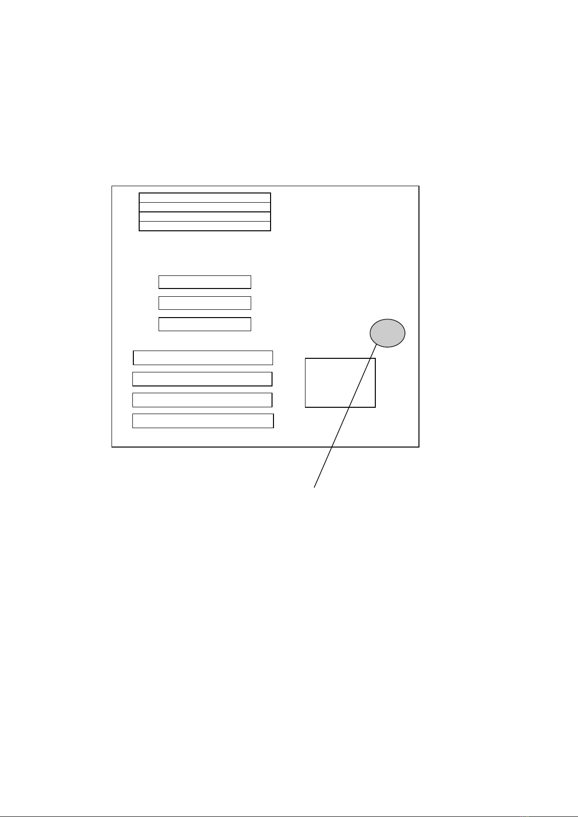
PT-730A offers a 64-bit programming architecture compatible with the software base of the 486,
586 microprocessor. It is a reliable motherboard using a UMC chipset and a multi-layer printed
circuit board. The chipset consists of UM8891AF (Host Bridge & Cache Memory Controller),
UM8892AF (Write Buffer Data Path Controller) and UM8886AF (ISA Bridge & System I/O
Controller) which provides the most cost effective and high performance solution for a PCI
PENTIUM computer system.
A block of 128K memory of the system DRAM is used for system and video shadow RAM to
increase the system performance. The video shadow RAM consists of four 16K pages which can
be enabled respectively.
PT-730A is a PCI Local Bus motherboard. The three PCI Local Bus slots fully comply with the
PCI (Peripheral Component Interconnect) Local Bus Specification Rev. 2.0. The speed of I/O
peripherals can be dramatically increased by connecting PCI compatible interface cards to the
PCI Local Bus slots on the PT-730A. We are the member of PCI SIG (Special Interest Group).
PT-730A is a green design mother-board which means when there is no system activity for a
specific period of time (this period is software programmable), the PT-730A will slow down its
original working frequency to zero. This will help to save the power consumption, reducing
energy related pollution and protecting our environment. PT-730A is also equipped with a unique
AUX Green connector which can be connected up to an external product, called an ‘ECO-PAD’
which can control the on/off switching of external power devices such as printers, monitors and
scanners, through the motherboard BIOS. If you do not use an ECO-PAD then the same
connector can also be used to control the vertical and horizontal sync of your monitor when
connected to a range of “PT-xxxx” VGA cards. For further information on the ECO-PAD or
other “PT” products please contact your dealer or sales representative.
"This is an ENERGY STARTM compliant product."
The Environmental Protection Agency ENERGY STARTM program defines that as an Ally of this
program the specified manufacturer must produce systems, or system components which enable a
computer system to operate and draw 30 watts or less of power in idle mode. Although the EPA do
not endorse any particular product or service, the program is designed to offer a cooperative effort
between the EPA and the component manufacturer (Ally) to provide energy saving products and
education to customers."
"It runs with Netware"
The PT-730A was authorized by Novell to use the Novell Yes, It runs with Netware certification
mark.

6
"FCC Approval"
The PT-730A motherboard has been approved for FCC Class B when properly installed in a
barebone configuration using the following case/power supply:
Brand Model FCC ID
Procase PC-109 SM JPJPINE429G109
Procase PC-609 T/M JPJPINE429G609
Procase PC-709 T/M JPJPINE429G709
FCC Notice:
Information to the User
This equipment has been tested and found to comply with the limits for a Class B digital device,
pursuant to Part 15 of FCC Rules. These limits are designed to provide reasonable protection against
harmful interference in a residential installation. This equipment generates, uses and can radiate radio
frequency energy and, if not installed and used in accordance with the instructions, may cause
harmful interference to radio communications. Should you experience interference to radio or
television reception then the user is encouraged to try to correct this interference by one or more of
the following measures:
Re-locate the receiving antenna.
Increase the separation between the equipment and receiver.
Connect the equipment into an outlet on a circuit different from that to which the receiver is
connected.
Consult the dealer or an experienced radio/TV technician for help and for additional suggestions.
The user may find the following booklet prepared by the Federal Communications Commission helpful:
“How to identify and Resolve Radio-TV Interference Problems.” This booklet is available from the US
Government Printing Office, Washington, DC20402, Stock No. 004-000-00345-4.
FCC Warning
The user is cautioned that changes or modifications not expressly approved by the manufacturer
could void the user’s authority to operate this equipment.
Note: In order for an installation of this product to maintain compliance with
the limits for a Class B device, shielded cables and power cord must be
used.
1.2 Checklist
Please check your PT-730A package to ensure that it contains the following items :
PT-730A Main Board
PT-730A User's Manual
PT-730A Enhanced IDE Driver Diskette
40-way flat cable 2 pieces
If any of these items are missing or damaged, please contact your local dealer or sales representative
for assistance.

7
1.3 Green PC Power Management
The Green PC mode is a state that minimizes power consumption. There are three different Green
PC modes :
1) Doze mode. This mode is available for all kinds of CPU. The clock of the CPU will slow
down to 8 MHz.
2) Standby mode. The clock of the CPU will slow down to the pre-set frequency.
3) Inactive mode / Sleep Mode. The PT-730A can stop the CPU clock under this mode.
The PT-730A extends the Green PC feature to a Green AUX connector (JP35). Through this
connector, the user can connect the PT-730A with an ECO-PAD or a range of “PT-xxxx” VGA
cards and IDE I/O cards which have the unique Green Aux connector. This enables :
ECO-PAD - Turn off video monitor,
ECO-PAD - Turn off printer (or other peripheral) power.
PT-xxxx VGA CARD - Turn off the vertical & horizontal sync of the monitor.
(Note : The hardware function on “PT-xxxx” VGA cards is more efficient than a green software
driver (screen saver) as it works with all types of software applications such as DOS or Windows. It
is completely independent of software being used at the time).
The PT-730A will be placed into Green PC mode as a result of one of the following events :
Suspend switch (JP6) is pressed.
Expiration of the internal Green PC Timer. The Green PC Timer is software
programmable which can configured in the "Power Management Setup" option of the
BIOS CMOS setup. The power management feature will be enabled as default, however
the timing may differ due to production control. It is recommended that you re-adjust
these timings according to your personal requirements/set-up.
Through system activity monitoring and management, the PT-730A will not go into Green PC mode
if any of the following activity is detected:
PCI Master 0 activity
PCI Master 1 activity
PCI Master 2 activity
PCI slave activity
LPT port activity
COM port activity
ISA master & DMA activity
IDE activity
Floppy activity
VGA activity
Keyboard activity
For further details on the ECO PAD, or ‘PTxxxx’ VGA and I/O cards please contact your local
dealer or sales representative for assistance.

8
2. SPECIFICATIONS
2.1 PT-730A System Board Specifications
IBM AT compatible.
Applied High performance CMOS technology.
Supports up to 64MB memory on board.
Mix 256K, 1M, and 4M SIMM (8 bit/32 bit) Module DRAM memory
256K, 512K, 1024K cache memory size selectable.
Fast CPU reset and Fastgate A20 logic.
Speed switching with hardware and software selection.
Board size 220 mm x 260 mm.
Four 16-bit ISA slots; three PCI slots (Master Mode).
Clock chip design makes CPU speed changing easier.
I/O slot signal protector on: IRQ9, DRQ2, 0WS#.
Green features to slow down / stop the CPU clock & turn off VGA display signals.
Supports both 3.3V & Mixed Mode cache RAM.
Supports ECO-PAD for turning off external power devices in green modes.
On-board enhanced IDE controller supports up to 4 HDD.
On-board CPU cooling fan power socket can be switched off automatically in green modes.
2.2 Jumpers and Connectors
Jumpers / Connector Description
PS1 Power Supply Connector
PS2 3.3V Power Supply Connector
KB1 Keyboard Connector
CN1 Battery Connector
CN2 Reset Switch
CN3 Speaker Connector
CN4 Turbo Switch
CN5 Turbo LED Connector
CN6 HDD LED
CN7 Power LED & Key-lock Connector
JP4 Clock Chip Speed Select
JP5 Flash ROM Type Select
JP6 Power Saving Switch
JP7 CPU Type Select
JP8 CPU Bus Frequency Select
JP9,JP10,JP11,JP12 Cache Size Select
JP13,JP14 Internal / External KB Controller Select
JP15 CPU Fan Control Select
JP16 ECO-PAD / PT-VGA Connector
JP17 CPU Fan Power Connector
JP18 Power Good Select
JP19,JP20 3.3V / Mixed Mode Cache RAM Select

9
To assist you in locating the necessary jumpers in order to configure your system, the following
graphical guide has been added for jumper location.
JUMPER / CONNECTOR POSITION
ISA
PCI SLOTS
CPU
SIMM

10
Default Setting
PS1: Power Supply Connector Pin Assignment
1 Power Good
2 +5V
3 +12V
4 -12V
5 Ground
6 Ground
7 Ground
8 Ground
9 -5V
10 +5V
11 +5V
12 +5V
This jumper is for the system case main power supply connector. This connector can only be attached
in one specific way to avoid any crossed signals/shorts. This also contains the ‘Power Good’ signal.
This is a signal from your power supply which recognizes that the system board is stable enough to
release its power to. Should your power supply not have a ‘Power Good’ signal, then you should
choose the internal ‘On-board Power Good’ on this motherboard as per jumper JP18.
PS2 : 3.3V Power Supply Connector Pine Assignment
1 + 3.3V
2 + 3.3 V
3 + 3.3 V
4 Ground
5 Ground
6 Ground
This jumper is for the system case main power supply connector which has 3.3V output. This
connector can only be attached in one specific way to avoid any crossed signals/shorts.
CN1: Battery Connector Pin Assignment
2-3 Normal on-board battery
3-4 Reset CMOS setting
For external battery: pin 1 is “+” ; pin 4 is “-”
Default is let this jumper open because the PT-730A has a Dallas RTC chip which has a battery
built-in. Should you set the CMOS incorrectly and wish to reset this, then change jumpers as

11
shown. Should you wish to use an external battery, pull off the jumper and ensure that the “+” and “-
” of the external battery pack cable are correct as shown.
CN2: Reset Switch
OPEN Normal
SHORT Reset
For the system reset switch on your system case.
Connect the cable here.
CN3: Speaker Connector
1 Speaker data
2 NC
3 Ground
4 + 5V
Connect the speaker cable from your system case here.
CN4: Turbo Switch
OPEN Turbo speed
CLOSE Normal speed (soft-key
disabled)
Connect the turbo switch cable from your system case here.
CN5: Turbo LED Connector
1 LED anode
2 LED cathode
Connect the TURBO LED from your case to here.

12
CN6: HDD LED Connector
1 LED anode
2 LED cathode
For the HDD LED of your system case, connect cable here.
CN7: Power LED & Key-lock Connector
1 + 5V
2 NC
3 Ground
4 Key-lock
5 Ground
For the power LED and Key-lock of your system case,
connect cables here.
JP4, JP8: Clock Chip Speed Select
CPU Speed Clock JP14 Pin
1-2
JP14 Pin
3-4
JP14 Pin
5-6
JP8
75 MHz 50
MHz
ON OFF OFF OFF
90 MHz 60
MHz
OFF ON OFF OFF
100 MHz 66
MHz
ON OFF ON OFF
120 MHz 60
MHz
OFF ON OFF ON
This selects the speed of the CPU signal to the clock chip.
JP5 : Flash ROM Type Select
1-2 5V Flash ROM
2-3 12V Flash ROM

13
This motherboard can use a FLASH ROM in order to
change the system BIOS through software. This allows
you to constantly update your system BIOS as changes
are made. Should you wish to use this feature then you
must set this jumper according to the voltage of that
FLASH ROM. Default is no connection because the PT-
730A uses only a EPROM as its standard feature. When
using FLASH ROM a Flash Memory Writer Utility
software driver is required. For details on this driver
please contact your dealer or sales representative.
JP6: Power Saving Switch
Press one time to go in suspend mode
Press another time to go back normal mode
Some system cases will also have a cable for a switch on
the case front which when pressed will automatically put
the system in to / and out of ‘suspend’ mode. Connect
that cable here .
JP7: CPU Type Select
OPEN Write Back CPU
SHORT Write Through CPU
This motherboard has been designed to work with both
Write Back & Write through type of CPU. Set this
according to the type of CPU used
JP9,JP10,JP11,JP12 : Cache Size Select
JP9 JP10 JP11 JP12 SRAM
256K OFF OFF OFF OFF 8K8 X 8
512K ON OFF ON OFF 64K8 X 4
1024K ON ON ON ON 128K8 X 8
This selects the size and type of cache ram on the
motherboard.
This motherboard can work with three types of cache ram
which
allows for extra flexibility should you wish to upgrade.
The jumpers will be set accordingly during production.
U18,U19,U20,U21,U22,U23,U24,U25 is the DATA RAM.

14
U17 is the TAG RAM.
JP13,JP14: Internal External KB Controller Select
The UMC chipset used on this motherboard has an internal
keyboard controller (KB BIOS). The motherboard design
also allows for an external KB BIOS chip for extra
flexibility should the parameters of the BIOS change. In
order for the system to recognize the keyboard signal you
must first tell it which KB BIOS you are using. Default is
internal.
JP13 JP14
Internal KBC OPEN OPEN
External KBC SHORT SHORT
JP15: CPU Fan Control Select
1-2 CPU fan control by green
mode
2-3 CPU fan always on
This motherboard has been equipped with an on-board
connector for the CPU cooling fan. The advantage of
this feature is that as well as the CPU, the cooling fan
itself can be switch off according to the power
management settings in the Green system BIOS. Here
there are options for control by BIOS or cooling fan
permanently on.
JP16: ECO-PAD / GREEN VGA & IDE Card Connector
1 + 5V For ECO PAD
2 Ground For ECO
PAD/VGA/IDE
3 Control signal ForECO
PAD/VGA/IDE
This connector can add further power saving Green
features to your system when used in conjunction with
either an ECO-PAD or ‘PT-xxxx’ Green VGA Card /
Green IDE I/O card with hardware connection. For
further details refer to the ‘Green PC Power Management’
section of this manual.

15
JP17: CPU Fan Power Connector Pin Assignment
1 +12V
2 Ground
3 Ground
12 +5V
This jumper is for the CPU cooling fan power
connection. This connector can only be attached in one
specific way to avoid any crossed signals/shorts.
JP18: Power Good Select
1-2 Internal Power good
2-3 External power good
Most power supplies produce a ‘Power Good’ signal
which recognizes that the system board is stable enough
to release the power to, however this motherboard also
includes an on-board Power Good circuit for additional
safety.
JP19,JP20: 3.3V / Mixed Mode Cache RAM Select
JP19 JP20
3.3V Cache RAM 1-2,3-4,5-6 OFF
Mixed Mode Cache
RAM
OFF 1-2,3-4,5-6
This motherboard can support Mixed Mode cache
RAM only. The jumpers will be set accordingly
during production
*** This board cannot support 5V cache
RAM. If you use 5V cache RAM, may
cause damage to the CPU.

16
2.3 SIMM MEMORY Configuration
This motherboard supports the 72-Pin SIMM memory.
72-Pin
This type of SIMM is a 32-bit module. (sometimes referred to as “..x32” or “..x36”). There are various types
of this module available ranging from 1MB capacity up to 32MB. However it should be noted that different
types can be split up into two groups - namely “single bank” and “dual bank”. The table below shows the
difference:
SIMM TYPE CAS Signals / bank
For 1 Pc SIMM
TOTAL MEMORY
For 1 Pc SIMM
256k x 32 (Non-
Parity)
one - single bank 1 MB
256k x 36 (Parity) one - single bank 1 MB
512k x 32 (Non-
Parity)
two - dual bank 2 MB
512k x 36 (Parity) two - dual bank 2 MB
1M x 32 (Non-
Parity)
one - single bank 4 MB
1M x 36 (Parity) one - single bank 4 MB
2Mx 32 (Non-
Parity)
two - dual bank 8 MB
2M x 36 (Parity) two - dual bank 8 MB
4M x 32 (Non-
Parity)
one - single bank 16 MB
4M x 36 (Parity) one - single bank 16 MB
8M x 32 (Non-
Parity)
two - dual bank 32 MB
8M x 36 (Parity) two - dual bank 32 MB
Since this motherboard supports the 586/Pentium processor, which has 64-bit architecture, you will require a
minimum of two pieces of SIMM (equal to 64-bit) in order to boot the system.
As such the four SIMM sockets of this motherboard can be looked upon as two separate 64-bit banks.
Although this motherboard can support both single-bank and double bank SIMM, it should be noted that you
cannot mix the two types within a 64-bit bank. Below is a diagram showing the correct and incorrect ways of
using single and dual banked SIMMs.
1M x 32/36 (Single Bank)
2M x 32/36 (Dual Bank)
Correct
64 bit bank
64 bit bank

17
1M x 32/36 (Single Bank)
2M x 32/36 (Dual Bank)
1M x 32/36 (Single Bank)
2M x 32/36 (Dual Bank)
As The UMC chipset of this motherboard supports up to 8 CAS signals. Each CAS signal is equal to one 32-
bit bank. Therefore it is possible to use 4 pcs. of dual-banked SIMM allowing up to 128MB on board
memory.
Incorrect
64 bit bank
64 bit bank

18
3. AWARD BIOS SETUP
3.1 Entering Setup
To enter Setup, press the <Del> key immediately at system power on or at system restart. The Main
Menu allows you to select from nine setup functions and two exit options. Use arrow keys to select
among the items and press <Enter> to accept or enter the sub-menu:
3.2 The Main Menu
ROM PCI / ISA BIOS (2A5X7PCH)
CMOS SETUP UTILITY
AWARD SOFTWARE, INC.
STANDARD CMOS SETUP PASSWORD SETTING
BIOS FEATURES SETUP IDE HDD AUTO DETECTION
CHIPSET FEATURES SETUP SAVE & EXIT SETUP
POWER MANAGEMENT SETUP EXIT WITHOUT SAVING
PCI/GREEN FUNCTION SETUP
LOAD BIOS DEFAULTS
LOAD SETUP DEFAULTS
Esc : Quit : Select Item
F10 : Save & Exit Setup (Shift) F2 : Change Color
Time, Date, Hard Disk Type...

19
3.3 Standard CMOS Setup
This setup page includes all the items in a standard compatible BIOS. The items are divided into 10
categories. Each category includes no, one or more than one setup items. Use the arrow keys to
highlight the item and then use the <PgUp> or <PgDn> keys to select the value you want in each item.
ROM PCI / ISA BIOS (2A5X7PCH)
STANDARD CMOS SETUP
AWARD SOFTWARE, INC.
Date
The date format is <day>, <date> <month> <year>. Press <F3> to show the calendar.
Time
The time format is <hour> <minute> <second>. The time is calculated based on the 24-hour military-
time clock. For example, 1 p.m. is 13:00:00.
Hard Drive type
The categories identify the types of hard disk drive C:, D:, E:, and F: that have been installed in the
computer. There are 46 predefined types(Type 1 to Type 46) and a user definable type (Type User).
Date (mm:dd:yy) : Tue, May 16 1995
Time (hh:mm:ss) : 17 : 54 : 42
HARD DISKS TYPE SIZE CYLS HEAD PRECOMP LANDZ SECTOR MODE
Primary Master : USER 425 989 15 65535 988 56 NORMAL
Primary Slave : None 0 0 0 0 0 0 ------------
Secondary Master : None 0 0 0 0 0 0 ------------
Secondary Slave : None 0 0 0 0 0 0 ------------
Drive A : 1.44M, 3.5 in.
Drive B : None Base Memory : 640K
Extended Memory : 7168K
Video : EGA/VGA Other Memory : 384K
Halt On : All Errors
Total Memory : 8192K
Esc : Quit : Select Item PU/PD/+/- : Modify
F1 : Help (Shift) F2 : Change Color

20
Press PgUp or PgDn to select a numbered hard disk type or type the number and press <Enter>. Note
that your drive specifications must match with the drive table; otherwise the hard disk will not work
properly. If your hard disk drive type is not matched or listed, please use Type User to define your own
drive type manually.
If you select Type User, related information is asked to be entered to the following items. Enter the
information directly from the keyboard and press <Enter>. This information should be provided in the
documentation from your hard disk vendor or the system manufacturer.
CYLS. number of cylinders in hard disk
HEADS number of heads
PRECOMP write precom
LANDZON the cylinder location where the heads park when the system is shut down
SECTORS number of sectors per track. MFM drives have 17 sectors per track. ESDI drives
have 34 sectors per track. SCSI and IDE drives may have even more sectors per
track.
MODE Normal: for hard disks smaller than 528MB
LBA: for hard disks larger than 528MB
Large: for hard disks that can only use with MS-DOS and
have a capacity larger than 528MB that do not use
LBA.
If a hard disk has not been installed select NONE and press <Enter>.
Note SCSI hard disks use device drivers that are support by current PC BIOS. Hence, don’t enter their
specifications here. For SCSI hard disk installation, please refer to the instructions that come with the
SCSI drive.
Floppy Drive A type/Drive B type
The category identifies the types of floppy disk drive A or drive B that have been installed in the
computer.
None No floppy drive installed
360K, 5.25 in 5-1/4 inch PC-type standard drive; 360 kilobyte capacity
1.2M, 5.25 in 5-1/4 inch AT-type high-density drive; 1.2 megabyte capacity
720K, 3.5 in 3-1/2 inch double-sided drive; 720 kilobyte capacity
1.44M, 3.5 in 3-1/2 inch double-sided drive; 1.44 megabyte capacity
2.88M, 3.5 in 3-1/2 inch double-sided drive; 2.88 megabyte capacity
Video
The category selects the type of adapter used for the primary system monitor that must match your video
display card and monitor. Although secondary monitors are supported, you do not have to select the type
in Setup.
Table of contents
Other Pine Technology Motherboard manuals