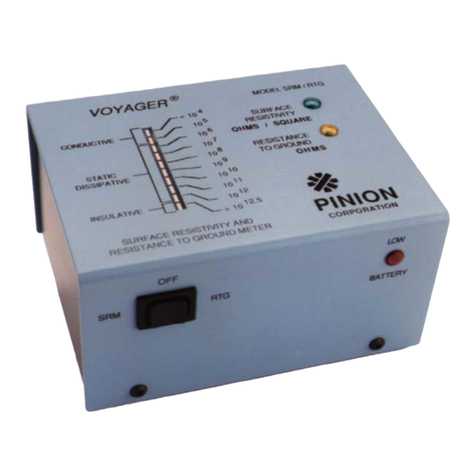
Pinion Voyager SRM-110 User manual

Pinion Products Corporation Inc.___________________________
INSTRUCTION MANUAL
SURFACE RESISTIVITY METER
SRM-110
IMPORTANT!! READ THIS MANUAL BEFORE OPERATING THIS UNIT.

THEORY OF OPERATION
The Pinion/Voyager model SRM-110 Combination Surface Resistivity meter is a simple
to use, highly repeatable measuring device for determining the surface resistivity of
materials, as well as resistance to ground. The SRM-110 incorporates a revolutionary
three-point probe measuring technique, enabling accurate, consistent, and repeatable
surface measurements. The principle of operation is as follows:
A voltage, V(30 Volts), is applied to each of the three outer probe contacts (Figure 1).
The center probe contact (spring loaded) provides a ground return of the current supplied
by the three outer probe contacts. The surface resistivity of the material being measured
is expressed as ten to some power, written as Ohms/Square = 10^x; where “x” is rounded
to the nearest integer by the SRM-110 with the following exceptions:
The 10^5 range covers10^4 to 10^5.5. This allows the first display segment to indicate
surface resistivities less than 10^4 Ohms/Square.
By studying the relationship between the outer probe contacts and the center probe
contact, the following is evident:
The diameter of the probe contact is 1/8 inch, and the distance from the outer contact to
the center probe is 1-½ inches. The approximate number of squares for a 1/8-inch strip of
material between the center probe and one of the outer probes is 12 (Figure 2). Three 12
square areas configured in parallel yield a 4 square resultant area (Figure 3). The
configuration in Figure e however still does not accurately include the entire area
measured by the SRM-110 probe arrangement. A more representative depiction of
current flow includes the entire circular area (Figure 4). There are more paths in parallel
further reducing the number of squares. The resulting number of squares was
experimentally determined to be 0.78. Experimental data was taken to determine the
effect of fringe current that exists outside the circular area encompassed by the probe
arrangement. These fringe affects were measured to be less than 1% (Figure 5). The
conductive elastomer probe contacts provide excellent contact to the surface under test.
For this reason, great pressure is not needed to perform a measurement. Each probe
contact of the SRM-110 applies a pressure of 40 lbs/in^2, due to the 2 pound weight of
the SRM-110, which is sufficient. The three-point probe design enables the unit to be
balanced on irregular and curved surfaces.
SPECIFICATIONS:
Display Segment Resistance Range (Ohms/Square)
10^4 <10^4
10^5 10^4.4 – 10^5.5
10^6 10^5.5 – 10^6.5
10^7 10^6.5 – 10^7.5
10^8 10^7,5 – 10^8.5
10^9 10^8.5 – 10^9.5
10^10 10^9.5 – 10^10.5
10^11 10^10.5 – 10^11.5
10^12 10^11.5 – 10^12.5
10^12.5 >10^12.5
Accuracy: Indicated exponent +/- .3

Power supply: Rechargeable NiCad or nickel metal hydride batteries (4 “C” size).
Test Voltage: 30 Volts +/- 2 Volts current limited to 2 mA.
Contact Area: 0.0123 sq in/probe
Contact Pressure: 40-lbs/sq in/probe.
Contact material: Conductive rubber.
Dimensions: 3”H x 4”D x 5” W
Weight: 2 pounds
Calibration Procedure:
The SRM-110 should be calibrated annually. If any step fails as per the following
instructions, the unit should be returned to Pinion Products Corporation Inc. for repair
and calibration. Pinion Products Corporation Inc. can provide both a standard NIST
Calibration with certification traceable to NIST and after calibration data, or a MIL
calibration with certification traceable to NIST and both before and after calibration data.
1.) The batteries should be charged before beginning the calibration procedure.
2.) Remove the 4 screws, two each side, from the unit, and set the cover to the side.
Leave the wires attached so that there is access to the printed circuit board.
Turn the unit “ON”.
3.) All voltage measurements are made relative to the unit ground. The test point for
ground is adjacent to the –15 and +15 volt test points.
4.) Use a 4-½ digit digital voltmeter such as a Keithley Model 175 Multimeter to
measure the voltage on the 30VTP. Record this voltage as V30.
5.) Measure and record the voltage at the +15V test point as V15.
6.) Calculate and record I(ref) using the formula: I(ref)= V30 x .04054
7.) Calculate and record R(tp1) using the formula R(tp1) = (V15-.236)/(I(ref)).
8.) Calculate and record I(O) using the formula I(O) = I(ref) x 1.016), (exponent –3)
9.) Calculate and record I(6) using the formula I(6) = I(ref) x .992), (exponent –9)
10.) Turn the unit off and remove the shorting jumper connected to TP1 and its
adjacent pin. Measure the resistance between the +15V test point and TP1
lead closest to R7. Adjust P1 until the measured resistance is equal to the
calculated value RTP1 +/- 1%.
11.) Replace the jumper on TP1 and the adjacent pin. Turn the unit on. Connect a
current source (e.g. Keithley Model 220) to the side of R6 connected to the
large round pad in the center of the board. Apply a current equal to the
calculated I(O). Measure the voltage on the test pin marked “OUT” and adjust
P2 until the measured voltage is 0.000 VDC +/- .050 VDC.
12.) Apply a current equal to calculated value I(6) to the same point as in step 11.
Measure the voltage on the test pin marked “OUT”, and adjust P3 until the
measured voltage is 6.000 VDC +/- .050 VDC.
13.) Apply a current equal to .003^-9 amperes. Measure the voltage on the test pin
marked “OUT”, and adjust P6 for a reading of 8.5 VDC +/- .05VDC. The
10^12.5 led should be illuminated.
14.) Apply a current equal to .03^-9 amperes. Measure the voltage on the test pin
marked “OUT”, and verify a reading of approximately 7.5 VDC. The 10^12

led should be illuminated.
15.) Measure the voltage on the pin marked +8.000 VDC and adjust P4 for a reading
of 8.000 VDC +/- .050 VDC.
16.) Measure the voltage on the pin marked –2.000 VDC and adjust P5 for a reading
of –2.000 VDC +/- .050 VDC.
17.) The calibration procedure is now complete. Place the cover back on the base and
replace the screws.
Operating Instructions:
1.) The SRM-110 is extremely simple to operate. Simply turn the unit on in the
“SRM” mode, and place it on the surface to be measured. The illuminated display
segment indicates the resistivity on the surface being measured. To insure
accurate readings, place small or thin samples on non-conductive surfaces (>
10^14 ohms/sq). Ideally, a clean glass surface.
2.) Measurements in the 10^11 to 10^12.5 may require a few seconds for the
illuminated display to stabilize.
3.) DO NOT operate the SRM-110 with the battery charger connected. The charger
will introduce electrical noise which will render readings inaccurate.
4.) Turn off the SRM-110 when it is not being used, and charge ONLY with the
supplied charger when the Low Battery indicator is illuminated, or at the end of
the day’s use. Charge for a minimum of 12 hours. Do NOT let the charger
connected continuously
Calibration Check:
1.) This is a “Quick” calibration check to verify the SRM-110 is performing within
tolerance.
2.) Connect a voltmeter between each of the three outer probe contacts relative to
ground (one at a time). The voltage should equal 30V +/- 2 V at each probe.
3.) Connect a programmable current source to the center probe contact and ground of
the SRM-110
4.) Apply the currents in the following table and check that the appropriate display
segment is illuminated.
Current (Amperes) Display Segment Tolerance
1.45 * 10^-3 <10^4 1%
4.95 * 10^-4 10^5 1%
3.77 * 10^-5 10^6 1%
3.84 * 10^-6 10^7 1%
3.85 * 10^-7 10^8 1%
3.85 * 10^-8 10^9 1%

3.85 * 10^-9 10^10 1%
3.85 * 10^-10 10^11 1%
3.85 * 10^-11 10^12 1%
6.00 * 10^-12 10^12.5 35%
5.) The calibration check is now complete. If any step failed, the SRM-110 requires
calibration. Please notify Pinion Products Corporation Inc. that the SRM-110
failed its calibration check, and information will be supplied on the procedure for
having the SRM-110 calibrated.
Accessories:
The following options and accessories are available for your SRM-110 Surface
Resistivity Meter:
SFS-100 Conductive Rubber probes (set of 4)
BFS-100 1” Diameter Conductive Rubber Probes (set of 4)
6550-0011 Replacement Battery Pack (each SRM contains two battery packs)
6120-0035 Replacement Battery Charger for SRM

Table of contents
Other Pinion Measuring Instrument manuals
