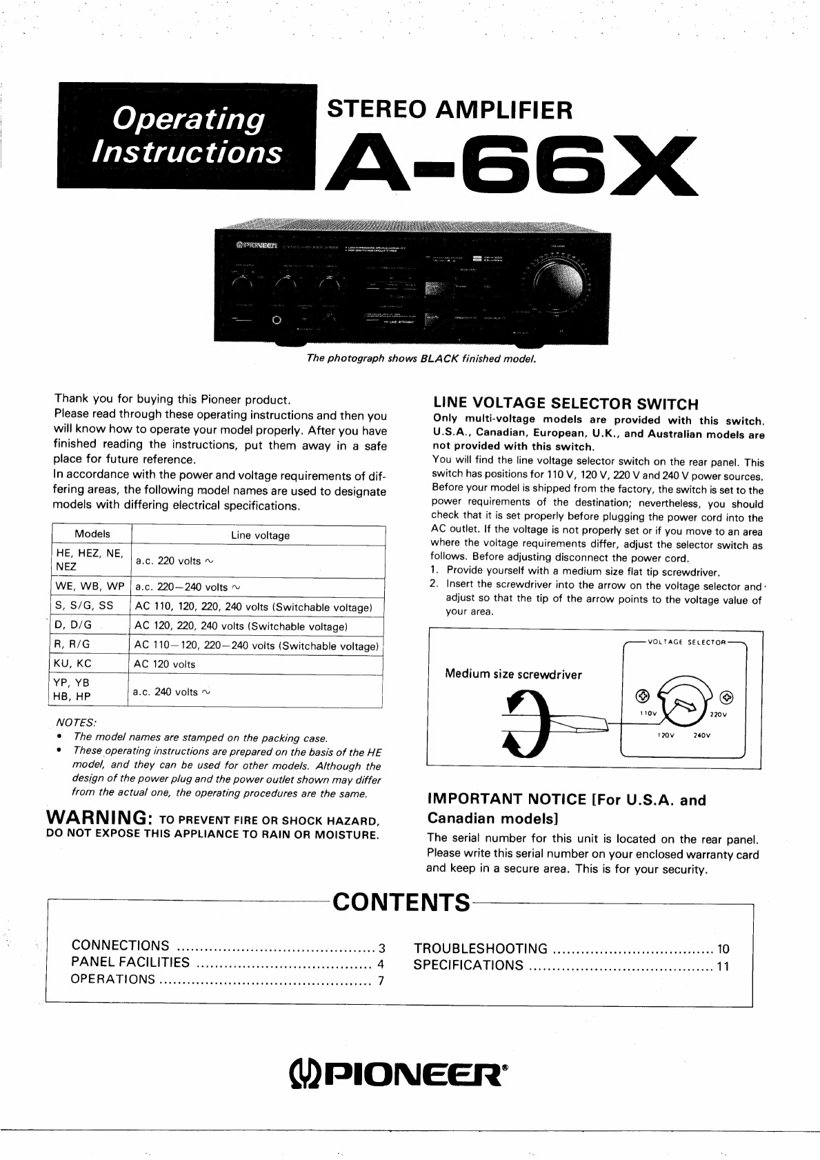
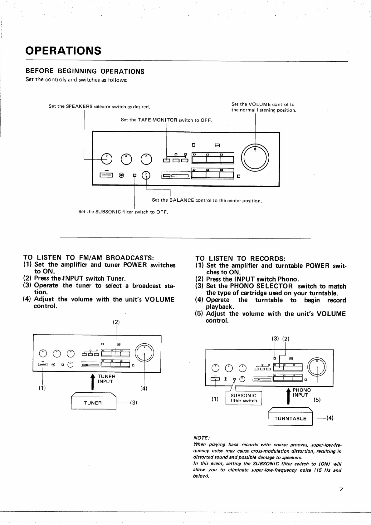
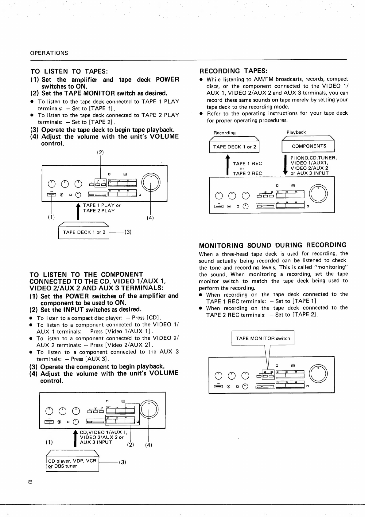
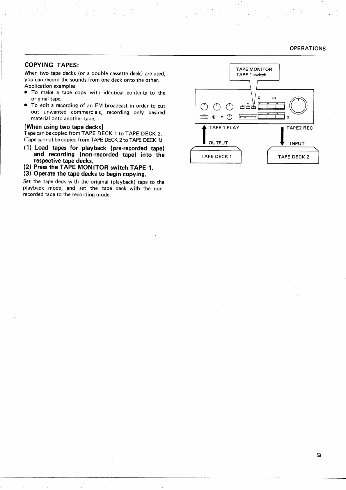
Pioneer A-66X User manual

Operating
Instructions
Thank
you
for
buying
this
Pioneer
product.
Please
read
through
these
operating
instructions
and
then
you
will
know
how
to
operate
your
model
properly.
After
you
have
finished
reading
the
instructions,
put
them
away
in
a
safe
place
for
future
reference.
In
accordance
with
the
power
and
voltage
requirements
of
dif-
fering
areas,
the
following
model
names
are
used
to
designate
models
with
differing
electrical
specifications.
Models
Line
voltage
Hees
NE,
a.c.
220
volts
~
NEZ
WE,
WB,
WP
|
a.c.
220—240
volts
~
al
S,
S/G,
SS
AC
110,
120,
220,
240
volts
(Switchable
voltage)
‘|
D,
D/G
AC
120,
220,
240
volts
(Switchable
voltage)
R,
R/G
|
AC
110—
120,
220—240
volts
(Switchable
voltage)
KU,
KC
|
AC
120
volts
YP,
YB
HB,
HP
a.c.
240
volts
~
_NOTES:
¢
The
model
names
are
stamped
on
the
packing
case.
°
These
operating
instructions
are
prepared
on
the
basis
of
the
HE
model,
and
they
can
be
used
for
other
models.
Although
the
design
of
the
power
plug
and
the
power
outlet
shown
may
differ
from
the
actual
one,
the
operating
procedures
are
the
same.
WARNING:
To
prevent
FIRE
OR
SHOCK
HAZARD,
DO
NOT
EXPOSE
THIS
APPLIANCE
TO
RAIN
OR
MOISTURE.
—
CONTENTS
STEREO
AMPLIFIER
A-66
The
photograph
shows
BLACK
finished
model.
LINE
VOLTAGE
SELECTOR
SWITCH
Only
multi-voltage
models
are
provided
with
this
switch.
U.S.A.,
Canadian,
European,
U.K.,
and
Australian
models
are
not
provided
with
this
switch.
You
will
find
the
line
voltage
selector
switch
on
the
rear
panel.
This
switch
has
positions
for
110
V,
120
V,
220
V
and
240
V
power
sources.
Before
your
model
is
shipped
from
the
factory,
the
switch
is
set
to
the
power
requirements
of
the
destination;
nevertheless,
you
should
check
that
it
is
set
properly
before
plugging
the
power
cord
into
the
AC
outlet.
If
the
voltage
is
not
properly
set
or
if
you
move
to
an
area
where
the
voltage
requirements
differ,
adjust
the
selector
switch
as
follows.
Before
adjusting
disconnect
the
power
cord.
1.
Provide
yourself
with
a
medium
size
flat
tip
screwdriver.
2.
Insert
the
screwdriver
into
the
arrow
on
the
voltage
selector
and:
adjust
so
that
the
tip
of
the
arrow
points
to
the
voltage
value
of
your
area.
VOLTAGE
SELECTOR
Medium
size
screwdriver
IMPORTANT
NOTICE
[For
U.S.A.
and
Canadian
models]
The
serial
number
for
this
unit
is
located
on
the
rear
panel.
Please
write
this
serial
number
on
your
enclosed
warranty
card
and
keep
in
a
secure
area.
This
is
for
your
security.
TROUBLESHOOTING
sy
eciessav
canes
rorruionsanecnens
10
SPECIFICATIONS
«o
worsi
crerieiaavlecsdasianeiagnmngels
11
WPIONEER’

READ
INSTRUCTIONS
—
All
the
safety
and
operating
instructions
should
be
read
before
the
appliance
is
operated.
RETAIN
INSTRUCTIONS
—
The
operating
instruc-
tions
should
be
retained
for
future
reference.
HEED
WARNING
—
Ali
warnings
on
the
appliance
and
in
the
operating
instructions
should
be
adhered
to.
FOLLOW
INSTRUCTIONS
—
All
operating
and
use
instructions
should
be
followed.
WATER
AND
MOISTURE
—
The
appliance
should
not
be
used
near
water
—
for
example,
near
a
bathtub,
washbowl,
kitchen
sink,
laundry
tub,
in
a
wet
basement,
or
near
a
swimming
pool,
etc.
LOCATION
—
The
appliance
should
be
installed
in
a
stable
location.
WALL
OR
CEILING
MOUNTING
—
The
appliance
should
not
be
mounted
to
a
wall
or
ceiling.
VENTILATION
—
The
appliance
should
be
situated
so
that
its
location
or
position
does
not
interfere
with
its
proper
ventilation.
For
example,
the
appliance
should
not
be
situated
on
a
bed,
sofa,
rug,
or
similar
surface
that
may
block
the
ventilation
open-
ings;
or,
placed
in
a
built-in
installation,
such
as
a
bookcase
or
cabinet
that
may
impede
the
flow
of
air
through
the
ventilation
openings.
HEAT
—
The
appliance
should
be
situated
away
from
heat
sources
such
as
radiators,
heat
registers,
stoves,
or
other
appliances
(including
amplifiers)
that
produce
heat.
POWER
SOURCES
—
The
appliance
should
be
con-
nected
to
a
power
supply
only
of
the
type
describ-
ed
in
the
operating
instructions
or
as
marked
on
the
appliance.
POWER-CORD
PROTECTION
—
Power-supply
cords
should
be
routed
so
that
they
are
not
likely
to
be
walked
on
or
pinched
by
items
placed
upon
or
against
them,
paying
particular
attention
to
cords
at
plugs,
convenience
receptacies,
and
the
point
where
they
exit
from
the
appliance.
POLARIZATION
—
If
your
purchased
product
is
pro-
vided
with
a
polarized
power
plug,
please
read
the
following
instructions.
This
product
is
equipped
with
a
polarized
alternating
current
line
plug
(a
plug
having
one
blade
wider
than
the
other).
This
plug
will
fit
into
the
power
outlet
only
one
way.
This
is
a
safety
feature.
If
you
are
unable
to
insert
the
plug
fully
into
the
outlet,
try
reversing
the
plug.
If
the
plug
should
still
fail
to
fit,
contact
your
electrician
to
replace
your
obsolete
outlet.
Do
not
defeat
the
safety
purpose
of
the
polarized
plug.
CLEANING
—
The
appliance
should
be
cleaned
only
with
a
polishing
cloth
or
a
soft
dry
cloth.
Never
clean
with
furniture
wax,
benzine,
insecticides
or
other
volatile
liquids
since
they
may
corrode
the
cabinet.
IMPORTANT
1
The
lightning
flash
with
arrowhead,
within
an
equilateral
triangle,
is
intended
to
alert
the
user
of
the
presence
of
uninsulated
'‘dangerous
voltage”
within
the
product's
enclosure
that
may
be
of
sufficient
magnitude
to
constitute
a
risk
of
electric
shock
to
persons.
IMPORTANT
2
If
the
apparatus
is
fitted
with
AC
mains
power
outlet(s),
see
REAR
PANEL
FACILITIES
for
convenient
connec-
tion
of
additional
Hi-Fi
component(s).
Make
all
connec-
tions
to
the
AC
outlet(s)
and
the
signal
terminals
first.
Connect
the
plug
to
the
wall
socket
last,
make
sure
that
the
power
switch
is
off.
Disconnect
the
wall
plug
when
the
equipment
is
not
in
(regular)
use,
e.g.
when
on
vacation.
SAFETY
INSTRUCTIONS
POWER
LINES
—
An
outdoor
antenna
should
be
located
away
from
power
lines.
NONUSE
PERIODS
—
The
power
cord
of
the
ap-
pliance
should
be
unplugged
from
the
outlet
when
left
unused
for
a
long
period
of
time.
OBJECT
AND
LIQUID
ENTRY
—
Care
should
be
taken
so
that
objects
do
not
fall
and
liquids
are
not
spilled
into
the
enclosure
through
openings.
charges.
OUTDOOR
ANTENNA
GROUNDING
—
If
an
outside
antenna
is
connected
to
the
antenna
terminal,
be
sure
the
antenna
system
is
grounded
so
as
to
provide
some
protection
against
voltage
surges
and
built
up
static
In
the
U.S.A.
section
810
of
the
Nationa!
Elec-
trical
Code,
ANSI/NFPA
No.
70-1984,
pro-
DAMAGE
REQUIRING
SERVICE
—
The
appliance
vides
information
with
respect
to
proper
should
be
serviced
by
Pioneer
authorized
service
center
or
qualified
service
personne!
when:
e
The
power-supply
cord
or
the
plug
has
been
damaged;
or
®
Qbjects
have
fallen,
or
liquid
has
been
spilled
into
the
appliance;
or
®
The
appliance
has
been
exposed
to
rain;
or
Fig.
A.
e
The
appliance
does
not
appear
to
operate
normally
or
exhibits
a
marked
change
in
performance;
or
e
The
appliance
has
been
dropped;
or
the
enclosure
damaged.
SERVICING
—
The
user
should
not
attempt
to
service
the
appliance
beyond
that
described
in
the
operating
instructions.
For
all
other
servicing,
con-
tact
the
nearest
Pioneer
authorized
service
center.
a)
~
<
POWER
LINES
oe.
GROUND
73
CLAMP
SERVICE
m
b)
ENTRANCE
CONDUCTORS
+
cE?)
STAND-OFF
—T
mast
f
INSULATORS
b
Ss
‘
a
if
c)
:
4
'
I
ANTENNA
LEAD
IN
WIRE
om
|
TO
EXTERNAL
ANTENNA
TERMINALS
OF
PRODUCT
a
t
|
GROUND
e
WIRE
a,b
ANTENNA
71
GROUND
DISCHARGE
UNIT
«
SERVICE
ENTRANCE
12
CLAMPS
EQUIPMENT
Hf
Py
GROUND
a
CLAMPS
GND
OPTIONAL
ANTENNA
GROUNDING
ELECTRODE
GROUND
WIRE
ab
Demon
.
t
'
'
c—
POWER
SERVICE
GROUNDING
ELECTRODE
SYSTEM
‘eg
interior
metal
water
pipe)
BONDING
ut
ORIVEN
8
FEET
(2
44
mi
JUMPER
d
iré
INTO
THE
EARTH
IF
i}
Reais
BY
i
LOCAL
CODES
SEE
FIG.A
u
NEC
SECTION
810
21
11)
grounding
of
the
mast
and
supporting
struc-
ture,
grounding
of
the
lead-in
wire
to
an
anten-
na
discharge
unit,
size
of
grounding
conduc-
tors,
location
of
antenna-discharge
unit,
con-
nection
to
grounding
electrodes,
and
re-
quirements
for
the
grounding
electrode.
See
Use
No.
10
AWG
(5.3
mm?)
copper,
No.
8
AWG
(8.4
mm?)
aluminum,
No.
17
AWG
(1.0
mm?)
copper-
clad
steel,
bronze
wire,
or
larger
as
ground
wire.
Secure
antenna
lead-in
and
ground
wires
to
house
with
stand-off
insulators
spaced
from
4
feet
(1.22
meters)
to
6
feet
(1.83
meters}
apart.
Mount
antenna
discharge
unit
as
closely
as
possible
to
where
lead-in
enters
house.
Use
jumper
wire
not
smaller
than
No.6
AWG
(13.3
mm?)
copper
or
equivalent
when
separate
antenna-ground-
ing
electrode
is
used.
CAUTION
RISK
OF
ELECTRIC
SHOCK
DO
NOT
OPEN
CAUTION:
TO
PREVENT
THE
RISK
OF
ELECTRIC
SHOCK,
DO
NOT
REMOVE
COVER
(OR
BACK).
NO
USER-
SERVICEABLE
PARTS
INSIDE.
REFER
SERVIC-
ING
TO
QUALIFIED
SERVICE
PERSONNEL.
FOR
USE
IN
THE
UNITED
KINGDOM
The
wires
in
this
mains
lead
are
coloured
in
accordance
with
the
following
code:
Blue:
Neutral
Brown:
Live
The
exclamation
point
within
an
equilateral
triangle
ts
intended
to
alert
the
user
of
the
presence
of
important
operating
and
maintenance
(servicing)
instructions
in
the
literature
accompanying
the
appliance.
As
the
colours
of
the
wires
in
the
mains
lead
of
this
ap-
paratus
may
not
correspond
with
the
coloured
marking
identifying
the
terminals
in
your
plug
proceed
as
follows:
The
wire
which
is
coloured
blue
must
be
connected
to
the
terminal
which
is
marked
with
the
letter
N
or
col-
oured
black.
The
wire
which
is
coloured
brown
must
be
connected
to
the
terminal
which
is
marked
with
the
letter
L
or
col-
oured
red.
Equipment
sold
in
the
U.K.
is
not
supplied
with
a
power
plug.

CONNECTIONS
OUTPUT
Turntable
OUTPUT
OUTPUT
fe
CD
player
Tuner
CONNECTING
SPEAKER
WIRES
1.
Strip
off
the
vinyl
covering
and
twist
the
tip
of
the
wire.
Twist
the
wire
core
2.
Loosen
the
knob
and
insert
the
wire
into
the
terminal
hole.
3.
Tighten
the
knob
to
fix
the
wire
in
place.
NOTE:
Do
not
allow
the
wire
core
to
protrude
and
touch
other
terminals
or
wires.
If
the
cores
of
differing
wires
touch,
damage
may
be
caused
to
your
components.
*
Auxiliary
input
terminal
Connect
the
following
products.
eCD
player,
tape
deck
or
tuner
e
Video
disc
player,
video
cassette
recorder,
TV
tuner
or
DBS
tuner
OUTPUT
OUTPUT
(REC)
|
{
(PLAY)
(REC)
|
|
(PLAY)
f
UN
Tape
deck
Tape
deck
INPUT
(Oo)
Speaker
system
A
(R)
|
INPUT
Speaker
system
A
(L)
Illustration
not
applicable
to
U.K.
model
Power
outlet
ne
INPUT
@e))
Speaker
system
B
(L)
OUTPUT
INPUT
INPUT
©e|
Speaker
system
B
(R)
CONNECTING
INPUT/OUTPUT
CORDS
Connect
the
white
plug
to
the
L
(left)
side,
and
the
red
plug
to
the
R
(right)
side.
Be
sure
to
push
the
plugs
in
securely.
L
side
@.
White
plug
R
side
Red
plug

PANEL
FACILITIES
REAR
PANEL
Turntable
ground
terminal
VIDEO
1/AUX
1
terminals
VIDEO
2/AUX
2
terminals
AUX
3
terminals
TAPE
2
terminals
(REC)
TAPE
1
terminals
(PLAY)
TAPE
1
terminals
(REC)
TUNER
terminals
CD
terminals
PHONO
terminals
(
AC
OUTLETS
(SWITCHED)
Power
supplied
through
these
outlets
is
turned
on
and
off
by
the
amplifier’s
POWER
switch.
Total
electrical
power
consumption
of
connected
equipment
should
not
exceed
100
W.
@)
AC
OUTLET
(UNSWITCHED)
Power
flows
continually
to
this
outlet,
regardless
of
whether
the
amplifier
is
switched
ON
or
OFF.
Electrical
power
consumption
of
the
connected
equipment
should
'
not
exceed
100
W.
The
equipment
should
be
disconnected
by
removing
the
mains
plug
from
the
wall
socket
when
not
in
regular
use,
e.g.
when
on
vacation.
NOTE:
Do
not
connect
appliances
with
high
power
consumption
such
as
heaters,
irons,
or
television
sets
to
the
AC
OUTLETS
in
order
to
avoid
overheating
or
fire
risk.
This
can
cause
the
amplifier
to
malfunction.
TAPE
2
terminals
(PLAY)
SPEAKERS
A
terminals
(right
channel)
SPEAKERS
A
terminals
(left
channel!)
SPEAKERS
B
terminals
(left
channel)
SPEAKERS
B
terminals
(right
channel)
—
(3)
Power
cord
Connect
this
cord
to
a
wall
outlet,
or
the
power
outlet
of
an
audio
timer.
About
Speaker
Impedance
When
speaker
systems
are
connected
to
only
one
of
the
SPEAKERS
A,
B
terminals,
such
speakers
should
have
rated
impedance
in
the
range
of
6—16
ohms.
When
speakers
are
connected
to
both
the
A
and
B
terminals,
they
should
have
a
rated
impedance
in
the
range
of
12—32
ohms.

FRONT
PANEL
SPEAKERS
ALANCE
@)
POWER
switch/indicator
Press
to
turn
power
to
the
unit
ON
and
OFF.
Depressed
position
(ON):
Power
is
supplied
to
the
unit.
Released
position
(OFF):
Power
to
the
unit
is
discon-
nected.
(2)
SPEAKERS
selector
switch
Use
to
select
the
speaker
systems
used
for
playback.
[OFF]
—No
sound
is
produced
from
the
speaker
systems.
Set
to
this
position
when
using
headphones.
[A]
—
Sound
is
produced
from
the
speaker
systems
con-
nected
to
the
SPEAKERS.A
terminals.
[B]
‘
—
Sound
is
produced
from
the
speaker
systems
con-
nected
to
the
SPEAKERS
B
terminals.
[A
+B]
—
Sound
is
produced
from
both
the
speaker
systems
connected
to
the
SPEAKERS
A
and
SPEAKERS
B
terminals.
(8)
BASS
tone
control
Use
to
adjust
the
low-frequency
tones.
The
central
‘‘0’’
position
is
the
flat
(normal)
position.
When
turned
to
the
right,
low-frequency
tones
are
emphasized;
when
turned
to
the
left,
low-frequency
tones
are
de-emphasized,
This
function
does
not
operate
when
the
LINE
STRAIGHT
switch
is
in
the
ON
position.
PANEL
FACILITIES
(a
PHONG
SELECTOR
0.2mv/1000
AMC,
=MM
LRN}
2-5
mvsaKa
@
TREBLE
tone
control
Use
for
adjusting
the
high-frequency
tones.
The
central
‘‘0’”’
position
is
the
flat
(normal)
position.
When
turned
to
the
right,
high-frequency
tones
are
emphasized;
when
turned
to
the
left,
high-frequency
tones
are
de-emphasized.
This
function
does
not
operate
when
the
LINE
STRAIGHT
switch
is
in
the
ON
position.
(6)
TAPE
MONITOR
switches/indicators
Use
this
switch
to
listen
to
tape
playback,
or
to
listen
to
the
sounds
being
recorded
during
tape
recording.
[TAPE
1]
—
Set
to
this
position
to
listen
to
the
playback
sound
of
the
tape
deck
connected
to
the
TAPE
1
PLAY
terminals,
or
to
monitor
the
sound
being
recorded
on
the
tape
deck
connected
to
the
TAPE
1
REC
terminals.
[OFF]
—
Leave
set
in
this
position
when
not
listening
to
tape
playback,
[TAPE
2]
—
Set
to
this
position
to
listen
to
the
playback
sound
of
the
tape
deck
connected
to
the
TAPE
2
PLAY
terminals,
or
to
monitor
the
sound
being
recorded
on
the
tape
deck
connected
to
the
TAPE
2
REC
terminals.
@
PHONO
SELECTOR
switch
Set
in
accordance
with
the
type
of
cartridge
used
in
your
record
turntable,

PANEL
FACILITIES
[MC]
—
Released
position;
set
to
this
position
when
using
|
an
MC
(moving
coil)
cartridge
|
[MM]
|
—
Depressed
position;
set
to
this
position
when
using
an
MM
(moving
magnet)
cartridge,
or
an
MC
(moving
coil)
cartridge
with
high
output
of
1
mV
or
more.
@
INPUT
switches/indicators
[CD]
—
Press
when
listening
to
a
compact
disc
playback
with
a
CD
player.
[Tuner]
—
Press
when
listening
to
AM
or
FM
broadcasts
with
a
tuner.
[Phono]
—
Press
when
listening
to
record
playback
on
a
turn-
table.
[Video
1/AUX
1]
—
Press
when
listening
to
programs
from
a
component
connected
to
the
VIDEO
1/AUX
1
terminals.
[Video
2/AUX
2]
—
Press
when
listening
to
programs
from
a
component
connected
to
the
VIDEO
2/AUX
2
terminals.
[AUX
3]
—
Press
when
listening
to
programs
from
a
component
connected
to
the
AUX
3
terminals.
VOLUME
control
This
control
is
used
for
controlling
the
sound
volume.
When
set
to
the
[%]
position,
sound
volume
is
turned
off;
when
set
to
the
[0]
position,
sound
volume
is
at
a
maxi-
mum.
(9)
PHONES
jack
When
using
headphones,
insert
their
plug
into
this
jack.
SUBSONIC
filter
switch
Use
this
switch
when
playing
records
with
coarse
grooves.
[OFF]
—
Released
position;
leave
in
this
position
for
normal
playback.
[15Hz]
—
Depressed
position;
in
this
position,
frequencies
of
15Hz
and
below
are
cut,
thus
eliminating
super-low-
frequency
noise
caused
by
coarse
record
grooves,
and
thus-helping
prevent
sound
distortion.
()
BALANCE
control
Should
normally
be
left
in
the
center
position.
Adjust
balance
if
the
sound
is
louder
from
one
of
the
speakers,
If
the
right
side
is
louder,
turn
toward
the
LEFT
position
and
if
the
left
side
is
louder,
turn
toward
the
RIGHT
position.
d2
LINE
STRAIGHT
switch
/indicator
By
using
this
switch,
the
input
signals
from
the
various
connected
peripheral
components
can
be
played
back
through
the
amplifier’s
modifying
(tone)
circuit,
or
bypassing
those
circuits.
When
the
indicator
is
lighted,
the
function
is
ON.
Input
signals
will
bypass
the
modifying
circuits
and
be
played
back
with
pure,
flat-balanced
tone.
When
set
to
OFF,
input
signals
will
pass
through
the
modifying
circuits
before
being
played
back,
thus
allowing
you
to
adjust
bass
and
treble
tone.
(3)
LOUDNESS
switch
Use
when
listening
at
low
volume
levels.
[OFF]
—
Released
position:
Should
normally
be
left
in
this
position.
[ON]
—
Depressed
position:
Boosts
low
and
high
frequen-
cies
to
give
added
punch
to
playback
even
at
low
volume.
This
function
does
not
operate
when
the
LINE
STRAIGHT
switch
is
in
the
ON
position.

OPERATIONS
BEFORE
BEGINNING
OPERATIONS
Set
the
controls
and
switches
as
follows:
Set
the
SPEAKERS
selector
switch
as
desired.
Set
the
VOLUME
control
to
the
normal
listening
position.
Set
the
TAPE
MONITOR
switch
to
OFF.
Set the
BALANCE
control
to
the
center
position.
Set
the
SUBSONIC
filter
switch
to
OFF.
TO
LISTEN
TO
FM/AM
BROADCASTS:
(1)
Set
the
amplifier
and
tuner
POWER
switches
to
ON.
(2)
Press
the
INPUT
switch
Tuner.
(3)
Operate
the
tuner
to
select
a
broadcast
sta-
tion.
(4)
Adjust
the
volume
with
the
unit’s
VOLUME
control.
(2)
TUNER
INPUT
|
TED
TO
LISTEN
TO
RECORDS:
(1)
Set
the
amplifier
and
turntable
POWER
swit-
ches
to
ON.
(2)
Press
the
INPUT
switch
Phono.
(3)
Set the
PHONO
SELECTOR
switch
to
match
the
type
of
cartridge
used
on
your
turntable.
(4)
Operate
the
turntable
to
begin
record
playback.
(5)
Adjust
the
volume
with
the
unit’s
VOLUME
control.
SUBSONIC
filter
switch
TURNTABLE
(4)
NOTE:
When
playing
back
records
with
coarse
grooves,
super-low-fre-
quency
noise
may
cause
cross-modulation
distortion,
resulting
in
distorted
sound
and
possible
damage
to
speakers.
In
this
event,
setting
the
SUBSONIC
filter
switch
to
[ON]
will
allow
you
to
eliminate
super-low-frequency
noise
(15
Hz
and
below).

OPERATIONS
TO
LISTEN
TO
TAPES:
(1)
Set
the
amplifier
and
tape
deck
POWER
switches
to
ON.
(2)
Set
the
TAPE
MONITOR
switch
as
desired.
@
To
listen
to
the
tape
deck
connected
to
TAPE
1
PLAY
terminals:
—
Set
to
[TAPE
1].
@
To
listen
to
the
tape
deck
connected
to
TAPE
2
PLAY
terminals:
—
Set
to
[TAPE
2].
(3)
Operate
the
tape
deck
to
begin
tape
playback.
(4)
Adjust
the
volume
with
the
unit’s
VOLUME
control.
(2)
TAPE
2
PLAY
TAPE
DECK
1
or
2
(3)
f
TAPE
1
PLAY
or
(1)
(4)
TO
LISTEN
TO
THE
COMPONENT
CONNECTED
TO
THE
CD,
VIDEO
1/AUX
1,
VIDEO
2/AUX
2
AND
AUX
3
TERMINALS:
(1)
Set
the
POWER
switches
of
the
amplifier
and
component
to
be
used
to
ON.
(2)
Set
the
INPUT
switches
as
desired.
@
To
listen
to
a
compact
disc
player:
—
Press
[CD].
@
To
listen
to
a
component
connected
to
the
VIDEO
1/
AUX
1
terminals:
—
Press
[Video
1/AUX
1].
@
To
listen
to
a
component
connected
to
the
VIDEO
2/
AUX
2
terminals:
—
Press
[Video
2/AUX
2].
@
To
listen
to
a
component
connected
to
the
AUX
3
terminals:
—
Press
[AUX
3].
(3)
Operate
the
component
to
begin
playback.
(4)
Adjust
the
volume
with
the
unit’s
VOLUME
control.
CD,VIDEO
1/AUX
1,
VIDEO
2/AUX
2
or
i
AUX
3
INPUT
(2)
(4)
(3)
RECORDING
TAPES:
@
While
listening
to
AM/FM
broadcasts,
records,
compact
discs,
or
the
component
connected
to
the
VIDEO
1/
AUX
1,
VIDEO
2/AUX
2
and
AUX
3
terminals,
you
can
record
these
same
sounds
on
tape
merely
by
setting
your
tape
deck
to
the
recording
mode.
@
Refer
to
the
operating
instructions
for
your
tape
deck
for
proper
operating
procedures.
Recording
Playback
TAPE
DECK
1
or
2
TAPE
1
REC
or
TAPE
2
REC
COMPONENTS
VIDEO
1/AUX1,
VIDEO
2/AUX
2
|
PHONO,CD,TUNER,
or
AUX
3
INPUT
MONITORING
SOUND
DURING
RECORDING
When
a
three-head
tape
deck
is
used
for
recording,
the
sound
actually
being
recorded
can
be
listened
to
check
the
tone
and
recording
levels.
This
is
called
‘monitoring’
the
sound,
When
monitoring
a
recording,
set
the
tape
monitor
switch
to
match
the
tape
deck
being
used
to
perform
the
recording.
@
When
recording
on
the
tape
deck
connected
to
the
TAPE
1
REC
terminals:
—
Set
to
[TAPE
1].
@
When
recording
on
the
tape
deck
connected
to
the
TAPE
2
REC
terminals:
—
Set
to
[TAPE
2].
TAPE
MONITOR
switch

OPERATIONS
COPYING
TAPES:
When
two
tape
decks
(or
a
double
cassette
deck)
are
used,
you
can
record
the
sounds
from
one
deck
onto
the
other,
Application
examples:
@
To
make
a
tape
copy
with
identical
contents
to
the
Original
tape.
@
To
edit
a
recording
of
an
FM
broadcast
in
order
to
cut
out
unwanted
commercials,
recording
only
desired
material
onto
another
tape.
[When
using
two
tape
decks]
[
TAPE
1
PLAY
|
TAPE2
REC
TAPE
MONITOR
TAPE
1
switch
Tape
can
be
copied
from
TAPE
DECK
1
to
TAPE
DECK
2.
(Tape
cannot
be
copied
from
TAPE
DECK
2
to
TAPE
DECK
1)
OUTPUT
INPUT
(1)
Load
tapes
for
playback
(pre-recorded
tape)
EA
IIS.
fee
and
recording
(non-recorded
tape)
into
the
(“aes
ccc?
|
respective
tape
decks.
(2)
Press
the
TAPE
MONITOR
switch
TAPE
1.
(3)
Operate
the
tape
decks
to
begin
copying.
Set
the
tape
deck
with
the
original
(playback)
tape
to
the
playback
mode,
and
set
the
tape
deck
with
the
non-
recorded
tape
to
the
recording
mode.

TROUBLESHOOTING
Incorrect
operations
are
often
mistaken
for
trouble
and
malfunctions.
If
you
think
that
there
is
something
wrong
with
this
component,
check
out
the
points
below.
Sometimes
the
trouble
may
lie
in
another
component.
Investigate
the
other
compo-
nents
and
electrical
appliances
being
used.
If
the
trouble
cannot
be
rectified
even
after
exercising
the
checks
listed
below,
ask
your
nearest
PIONEER
authorized
service
center
or
your
dealer
to
carry
out
repair
work.
Symptom
No
power
supplied
to
unit.
|
No
sound,
[During
tape
playback]
[In
other
cases]
No
sound
from
one
speaker.
Can't
record
tapes.
@
Operation
of
tape
deck
is
mistaken.
Can't
perform
tape
copying.
10
Probable
Cause
@
Power
plug
is
disconnected
from
outlet.
@
The
component's
power
plug
has
been
plugged
into
another
component's
power
outlet
(e.g.
timer,
etc.),
but
power
to
that
unit
is
disconnected.
e@
Connecting
cords
are
disconnected
from
terminals,
or
connected
incorrectly.
e
Terminals
or
connecting
cords’
pin
plugs
are
dirty.
e
The
SPEAKERS
selector
switch
is
set
to
the
OFF.
@
TAPE
MONITOR
switch
is
set
to
OFF.
e
Mistaken
tape
operation
e
The
INPUT
switch
selected
does
not
match
the
component
being
played
back.
@
Operation
of
other
components
is
mistaken.
e
Connecting
cords
or
speaker
wires
are
disconnected
to
that
side.
e
BALANCE
control
have
been
adjusted
to
one
side.
e
The
TAPE
MONITOR
switch
is
set
to
OFF
or
TAPE
2.
e
Operation
of
tape
decks
is
mistaken.
Remedy
@
{insert
plug
securely
in
outlet.
@
Turn
on
power
to
other
component.
e
Connect
securely.
e@
Clean
terminals
and
plugs.
e
Set
switch
to
ON
(A
or
B)
e
Set
switch
to
ON
(TAPE
1
or
TAPE
2).
e
Consult
the
operating
instructions
for
your
tape
deck.
e@
Set
switches
correctly
(Phono,
Tuner,
CD,
Video
1/AUX
1,
Video
2/AUX
2,
AUX
3).
e@
Consult
the
operating
instructions
for
the
other
components.
e
Connect
securely.
e
Adjust
BALANCE
control
to
center
position.
@
Consult
the
operating
instructions
for
the
tape
deck.
e@
Set
switches
correctly
(TAPE
1).
@
Consult
the
operating
instructions
for
the
tape
decks.

SPECIFICATIONS
Amplifier
Section
Continuous
average
power
output
is
80
watts*
per
channel,
min.,
at
8
ohms
from
20
Hertz
to
20,000
Hertz
with
no
more
than
0.007%
total
harmonic
distortion.
Continuous
Power
Output
(both
channels
driven)
20
Hz
to
20
kHz,
0.007%,60
........
90W
+90W
20
Hz
to
20
kHz,
0.007%,
8Q2
........
80
W
+
80
W
DIN
Continuous
Power
Output
(both
channels
driven)
We
a
Fei
bs
=
a
a
95W+95W
Dynamic
Power
BOI4A
O72
O
ge
on
cd
OO
Ken
a
Poa
Me
115W/180W/220W
Total
Harmonic
Distortion
20
Hz
to
20
kHz,
80W,80Q.............
0.007%
Cross-harmonic
Distortion
(50
Hz:
7
kHz
=
4:
1)
Continuous
power
output
..........0
005
0.007%
Output
Bandwidth
(IHF
-
both
channels
driven)
OOo
ote
etal
Sg
a
ade
hae
Bean
mete
5
Hz
to
45
kHz
Damping
Factor
DPN
Z
2
5
oe
tae
Hh
aha
PRS
A
Rg
San
60
Input
(sensitivity/impedance)
PHONO
MM.............
0000:
2.5
mV/50
kQ
PHONO
(MG
gasses
och
aces
coe
eo
0.2
mV/100
Q2
TUNER,
CD,
TAPE
PLAY,
VIDEO/AUX
150
mV/50
kQ2
Overload
Level
PHONO
MM
1
kHz,
0.007%.............
160
mV
PHONO
MC
1
kHz,
0.007%
..............
12
mV
Cartridge
load
capacity/load
impedance
PHONO
MM
............0.000-
220
pF/50
kQ
Output
(level/impedance)
TAPE.
REC
oivgvactoy
nike
ee
ates
150
mV/2.2
kQ
Frequency
Response
PHONO
MM
20
Hzto
20kHz
...........
+0,.3
dB
—0.3
dB
PHONO
MC
20
Hzto
20kHz
...........
+0.5
dB
—0.5
dB
TUNER,
CD,
VIDEO/AUX
5Hz
to
100kHz.
...+0dB
—3
dB
Tone
Control
BGO
ick
Xe
ied
Ware
ce
NOE
Ge
Bie
ea
+8
dB
100
Hz
—8
dB
DEFY
BE
w
aie
See
eas
ole
Bek
we
Kha
lee
+
8dB
10
kHz
—8
dB
Filter
LOW
(SUBSONIC).............
15
Hz
6dB/oct
Loudness
contour
(volume
control
set
at
—30
dB
position)
......
+6dB
100
Hz/+3
dB
10
kHz
Hum
and
Noise
(Short
circuited,
A
network)
PHONO:
MM
aces
Sa
Gi
dw
weal
Soe
ato
86
dB
PHONG
IMG
35
sda.
aw
arate
oe ae
eee
Be
70
dB
TUNER,
CD,
TAPE
PLAY,
VIDEO/AUX......
105
dB
Hum
and
Noise
(DIN,
continuous
power/50
mW)
PHONO
MM...........
000022
eae
74
dB/64
dB
TUNER,
CD,
TAPE
PLAY,
VIDEO/AUX.
.
84
dB/65
dB
Miscellaneous
Power
requirements
HE
model
...............
a.c.
220
V
~,
50/60
Hz
HB,
YP
models............
a.c.
240
V
~,
50/60
Hz
Power
Consumption
HE
HB,
YP
models
ss
oi1n
eee
ss
see
ees
600
W
Dimensions
.........
420
(W)
x
416
(D)
x
134
(H)
mm
16-9/16(W)
x
16-3/8(D)
x
5-1/4(H)
in
Weight
(without
package)............
10.9
kg/23
Ib
15
oz
Furnished
Parts
Operating
Instructions...
2.0...
0.0.0
eee
eee
1
NOTES:
®
Specifications
and
design
subject
to
possible
modification
without
notice
due
to
improvement.
@
*Measured
pursuant
to
Federal.
Trade
Commission’s
Trade
Regulation
rule
on
Power
Claims
for
Amplifiers.
[For
Canadian
model]
CAUTION:
to
prevent
ELECTRIC
SHOCK
DO
NOT
USE
THIS
(POLARIZED)
PLUG
WITH
AN
EXTENSION
CORD,
RECEPTACLE
OR
OTHER
OUTLET
UNLESS
THE
BLADES
CAN
BE
FULLY
INSERTED
TO
PREVENT
BLADE
EXPOSURE.
ATTENTION:
pour
prevenir
LES
CHOCS
ELEC-
TRIQUES
NE
PAS
UTILISER
CETTE
FICHE
POLARISEE
AVEC
UN
PROLONGATEUR
UNE
PRISE
DE
COURANT
OU
UNE
AUTRE
SORTIE
DE
COURANT,
SAUF
SI
LES
LAMES
PEUVENT
ETRE
INSEREES
A
FOND
SANS
EN
LAISSER
AUCUNE
PARTIE
A
DECOUVERT.
|
11
Table of contents
Other Pioneer Amplifier manuals

Pioneer
Pioneer A-107 User manual

Pioneer
Pioneer A-8 User manual

Pioneer
Pioneer A-702R User manual

Pioneer
Pioneer A-88X User manual

Pioneer
Pioneer A-777 User manual

Pioneer
Pioneer GM-X402-02 User manual

Pioneer
Pioneer A-201 User manual

Pioneer
Pioneer GM-X422 User manual

Pioneer
Pioneer PRS-X340 User manual

Pioneer
Pioneer GM-6100F User manual

Pioneer
Pioneer GM-6200F/XU/UC User manual

Pioneer
Pioneer GM-620 User manual

Pioneer
Pioneer GM-D8604 User manual

Pioneer
Pioneer SA-560 User manual

Pioneer
Pioneer GM-D9605 User manual

Pioneer
Pioneer PRS-X720 User manual

Pioneer
Pioneer A-09 User manual

Pioneer
Pioneer M-LA21 User manual

Pioneer
Pioneer PRS-D3000SPL/X1H/EW User manual

Pioneer
Pioneer SX-R9 User manual