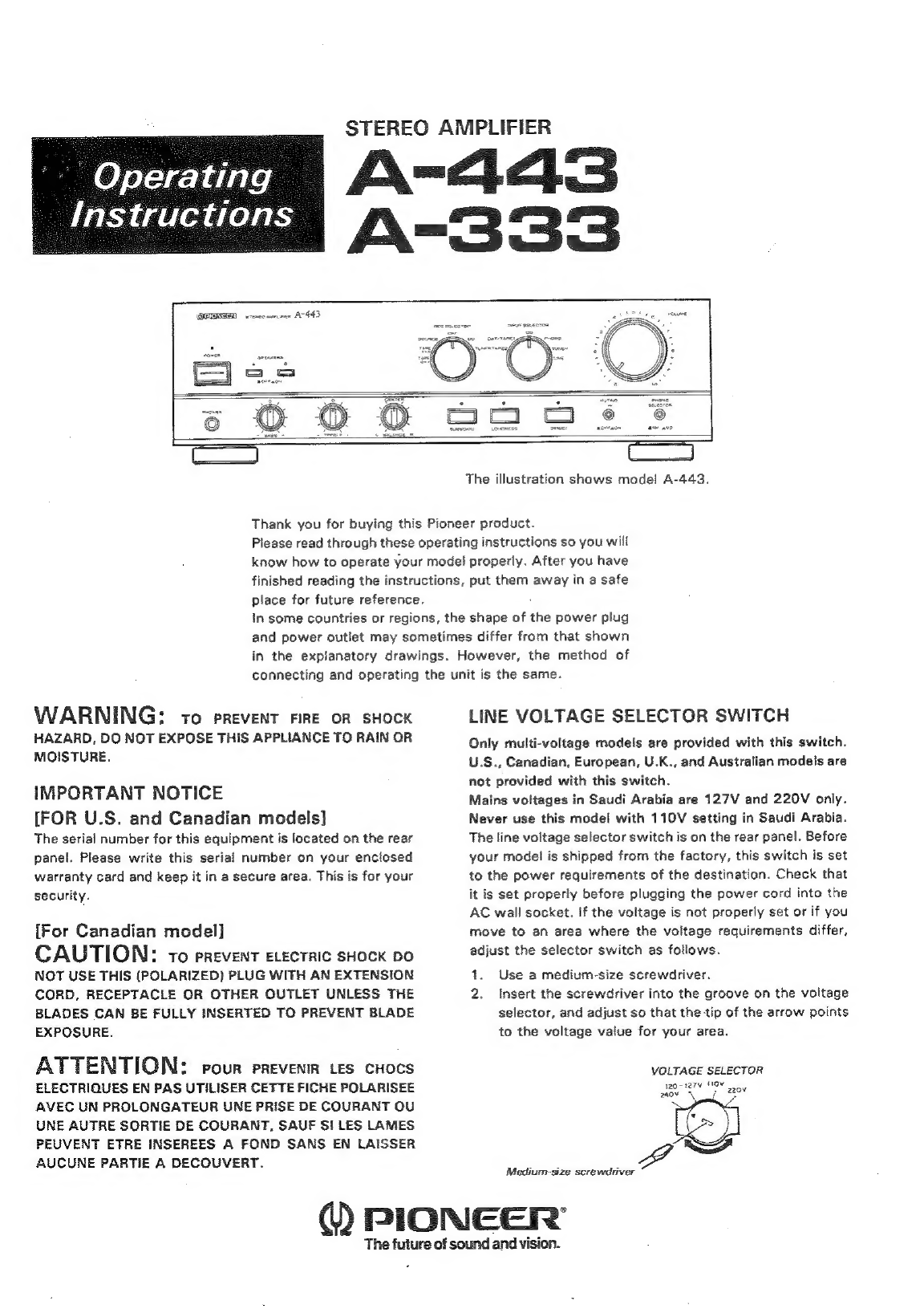
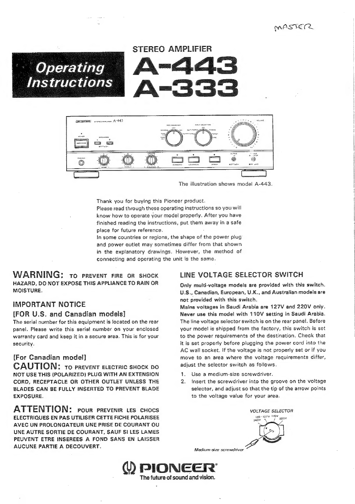
Pioneer A-443 User manual
Other Pioneer Amplifier manuals

Pioneer
Pioneer GM-5500T User manual

Pioneer
Pioneer SA-730 User manual

Pioneer
Pioneer GM-6400F/XJ/UC User manual

Pioneer
Pioneer A-303R User manual

Pioneer
Pioneer A-400 User manual

Pioneer
Pioneer GM5400T - Bridgeable Amplifier User manual

Pioneer
Pioneer A-307R A-209R User manual

Pioneer
Pioneer PRS-D1000M User manual

Pioneer
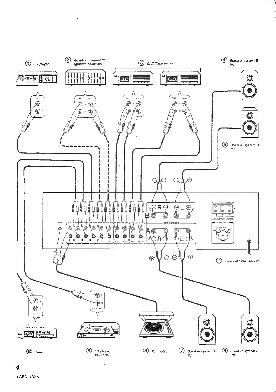
Pioneer A-443 User manual

Pioneer
Pioneer GM-H120 User manual

Pioneer
Pioneer QX-949 User manual

Pioneer
Pioneer Elite M-10X User manual

Pioneer
Pioneer FH-P404 UC User manual

Pioneer
Pioneer GM-X1024 User manual

Pioneer
Pioneer PRS-D410 User manual

Pioneer
Pioneer A-757 User manual

Pioneer
Pioneer GM-3500T/XZUC User manual

Pioneer
Pioneer ND-G500XS User manual

Pioneer
Pioneer SA-1040 User manual

Pioneer
Pioneer KEH-P5000 User manual