manuals.online logo
Brands
  1. Home
  2. •
  3. Brands
  4. •
  5. Pioneer
  6. •
  7. Amplifier
  8. •
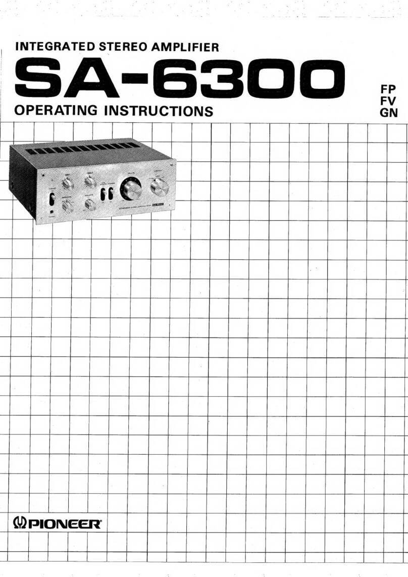
  9. Pioneer A-P6500 User manual

Pioneer A-P6500 User manual

@)
PIONEER
The
Art
of
Entertainment
Service
Manual
STEREO
AMPLIFIER
A-P6500
@
This
product
is
a
component
of
a
system.
Refer
to
the
service
manual
RRV1627
for
XS-P6500.
@
This
product
does
not
function
properly
when
independent;
to
avoid
malfunctions,
be
sure
to
connect
it
to
the
prescribed
system
component(s),
otherwise
damage
may
result.
ORDER
NO.
RRV1628
@
XS-P6500
is
a
combination
of
the
following
components.
STEREO
AMPLIFIER
:
A-P6500
STEREO
TUNER
:
F-P5500RDS
COMPACT
DISC
PLAYER
:
PD-P5500
STEREO
DOUBLE
CASSETTE
DECK
:
CT-P5500WR
PIONEER
ELECTRONIC
CORPORATION
=
4-1,
Meguro
1-Chome,
Meguro-ku,
Tokyo
153,
Japan
PIONEER
ELECTRONICS
SERVICE,
INC.
P.O.
Box
1760,
Long
Beach,
CA
90801-1760,
U.S.A.
PIONEER
ELECTRONIC
(EUROPE)
N.V.
—
Haven
1087
Keetbergiaan
1,
9120
Melsele,
Belgium
PIONEER
ELECTRONICS
ASIACENTRE
PTE.
LTD.
501
Orchard
Road,
#10-00
Lane
Crawford
Place,
Singapore
0923
©
PIONEER
ELECTRONIC
CORPORATION
1996
T-SZK
MAY
1996
Printed
in
Japan
Wd)
PIONEER’
The
Art
of
Entertainment
Service
Manual
—
RRV1627
SEPARATE
MINI
COMPONENT
SYSTEM
XS-P6500
@
Refer
to
the
service
manual
RRV1525
for
XS-P5500.
THIS
MANUAL
IS
APPLICABLE
TO
THE
FOLLOWING
MODEL(S)
AND
TYPE(S).
MYIXK
i
|
AC220-230V
MYXK/EA
AC220-230V
@
XS-P6500
is
a
combination
of
the
following
components.
STEREO
AMPLIFIER
:
A-P6500
STEREO
TUNER
:
F-P5500RDS
COMPACT
DISC
PLAYER
:
PD-P5500
STEREO
DOUBLE
CASSETTE
DECK
:
CT-P5500WR
@
This
product
does
not
function
properly
when
independent;
to
avoid
malfunctions,
be
sure
to
connect
it
to
the
prescribed
system
component(s),
otherwise
damage
may
result.
@
This
product
is
a
component
of
a
system.
For
the
system
composition
STEREO
TUNER:
F-P5500,
COMPACT
DISC
PLAYER:
PD-P5500
and
STEREO
DOUBLE
CASSETTE
DECK
:
CT-P5500WR
etc.,
refer
to
the
service
manual
RRV1525
for
XS-P5500.
@
This
manual
is
applicable
to
STEREO
AMPLIFIER:
A-P6500.
CONTENTS
1.
EXPLODED
VIEWS,
PACKING
AND
PARTS
LIST
......2
4,
PCB
PARTS
LIST
.....ssssssssssssesessssssseeeeesssnssnnneeceernssi
19
2.
BLOCK
DIAGRAM
...sssssssssssssssstsssstnsssesssastnsseeenseee
6
BIC
INFORMATION
.sccsssssssssssssessssscetsnssseeseenseneeen
22
3.
SCHEMATIC
AND
PCB
CONNECTION
DIAGRAMS:
csilanatitancaen.isi
a
cidutianamianennates
7
PIONEER
ELECTRONIC
CORPORATION
4-1,
Meguro
1-Chome,
Meguro-ku,
Tokyo
153,
Japan
PIONEER
ELECTRONICS
SERVICE,
INC.
P.O.
Box
1760,
Long
Beach,
CA
90801-1760,
U.S.
A.
PIONEER
ELECTRONIC
(EUROPE)
N.V.
Haven
1087
Keetberglaan
1,
9120
Melsele,
Belgium
PIONEER
ELECTRONICS
ASIACENTRE
PTE.
LTD.
501
Orchard
Road,
#10-00
Lane
Crawford
Place,
Singapore
0923
©
PIONEER
ELECTRONIC
CORPORATION
1996
T-SSK
MAY
1996
Printed
in
Japan
XS-P6500
1.
EXPLODED
VIEWS,
PACKING
AND
PARTS
LIST
NOTES:
©
Parts
marked
by
“NSP”
are
generally
unavailable
because
they
are
not
in
our
Master
Spare
Parts
List.
©
The
A
mark
found
on
some
component
parts
indicates
the
importance
of
the
safety
factor
of
the
parts.
Therefore,
when
replacing,
be
sure
to
use
parts
of
identical
designation.
®
Parts
marked
by
“@”
are
not
always
kept
in
stock.
Their
delivery
time
may
be
longer
than
usual
or
they
may
be
unavailable.
1.1
PACKING
Mark
No.
Description
Parts
No.
Mark
No.
Description
Parts
No.
1
PADB
RHA1190
11
CONTROL
CODE
RDE1041
2
PADT
RHAI191
12
OPERATING
INSTRUCTIONS
RRD1179
3.
SPACER
RHG1713
(German/Italian)
4
OPERATING
INSTRUCTIONS
RRD1180
(MYIXK,
MYXK/EA
types)
(French/Dutch)
(MY
XK/EA
type)
13.
OPERATING
INSTRUCTIONS
RRB1171
5
MASTER
CARTON
RHG1743
(English)
(NVXK,
MY
XK/EB
types)
NSP
14
BATTERY
(R03,
AAA)
VEM-022
6
SEAT
(550x550x0.5)
Z23-026
15
POLYETHYLENE
BAG
Z21-038
7
FMANTENNA
ASSY
ADHI1019
(0.03x230x340)
8
LOOP
ANTENNA
ATB7002
16
OPERATING
INSTRUCTIONS
RRD1181
9
REMOTE
CONTROL
UNIT
RPX1085
(French/Swedish/Spanish/Portuguese)
10
BATTERY
COVER
AZA7050
(MY
XK/EB
type)
16
(MYXK/EB
Type)
13
(NVXK,
MYXK/EB
Types)
12
(MYIXK,
MYXK/EA
Types)
4
(MYXK/EA
Type)
1.2
STEREO
AMPLIFIER
(A-P6500)
™@
PARTS
LIST
Mark
No.
NSP
WaArhWN—
NSP
NSP
ceoanan
NSP
14
NSP
15
NSP
16
NSP
17
NSP
19
NSP
20
Description
DISPLAY
ASSY
MAIN
ASSY
H.
P.
ASSY
VR
DOL.
PROLOG.
ASSY
CONNECT
ASSY
AC.
CONNECT
ASSY
REC.
OUT
ASSY
BAL
VR
ASSY
STRAIN
RELIEF
AC
POWER
CORD
(Except
NVXK
type)
AC
POWER
CORD
(NVXK
type)
28P F-F-C/30V
FUSE
(T1.25A,
FU2001)
POWER
TRANSFORMER
(T1)
FOOT
SPACER
PC
SUPPORT
PCB
MOLD
CORD
STOPPER
CUSHION
B
UNDER
BASE
HEAT
SINK
DC
FAN
MOTOR
SPRING
INSULATOR
ASSY
MIC
VOLUME
KNOB
STA.
LENS
BUTTON
AM
TIMER
BUTTON
NAME
PLATE
VR
KNOB
PANEL
AM
D.
PANEL
AM
BONNET
REAR
BASE
(Except
NVXK
type)
REAR
BASE
(NVXK
type)
SCREW
(WITH
WASHER)
SCREW
SCREW
SCREW
SCREW
SCREW
NUT
Parts
No.
RWZ3882
RWZ3920
RWZ3926
RWZ3921
RWZ3924
RWZ3925
RWZ3883
RW2Z3927
CM-22B
ADG1138
PDG1055
RDD1358
AEK1055
RTT1315
REB1296
VEC1549
AMR2115
DNF1128
REB1282
RNB1115
RNE1862
AXM7003
RBK1071
VXA1881
AAB7045
AAK7118
RAC2111
RAC2107
PAM1407
RNK2160
RAH2701
RAH2711
REA1181
RNA2074
RNA2081
ABA1005
BBZ30P100FCC
BBZ30PO80FZK
BBZ30P160FMC
ASZ40P060FMC
BMZ40P300FZK
NB40FMC
XS-P6500
Mark
No.
Description
Parts
No.
41
BINDER
ZCA-SKB90BK
42
POWER
AMP
ASSY
RWZ3879
43
REG.
ASSY
RWZ3923
44
SCREW
BPZ30PO80FMC
45
SCREW
BSZ30PO80FZK
A
46
FUSE(TSA)
(NVXK
type
only)
REK1003
47
REAR
POWER
AMP
ASSY
RWZ3922
NSP
48
MINICARD
SPACER
REC1278
NSP
49
HOLDER
RNE1856
50
LOGIC
LENS
RNK2193
51
SCREW
VBZ30P120FZK
XS-P6500
M@
EXPLODED
VIEWS
32
NOTE:
Screws
adjacent
to
W
mark
on
the
product
are
used
for
disassembly
XS-P6500
XS-P6500
BLOCK
DIAGRAM
2.
yV3ud
ds
HJINSO
0
OO
ey
L$8zol
dwv
dWVYSMOd
=dWVY
A
NIV
dS
LNOWS
iS)
O
On
©
_
|
#S9Z01
€0%zZ91
Ow Ow
ON
ony
o~
O~
|wadina}Yyasina
=
er
z
.
YHANNL
‘GO
dad
adv
dV
be
©)1NO
93H
108zol
XS-P6500
3.
SCHEMATIC
AND
PCB
CONNECTION
DIAGRAMS
3.1
OVERALL
SCHEMATIC
DIAGRAM
(PD-P5500
)
COMPACT
DISC
PLAYER
SECTION|9
OOOOOOO00000
MOOOOCOOOOCOO00000®
CN1Q01
NOTE
FOR
SCHEMATIC
DIAGRAMS
(Type
1A)
1.
When
ordering
service
parts,
be
sure
to
refer
to
“PARTS
LIST
of
EXPLODED
VIEWS”
or
“PCB
PARTS
LIST”.
.
Since
these
are
basic
circuits,
some
parts
of
them
or
the
values
of
some
components
may
be
changed
for
improve-
ment.
RESISTORS:
Unit:
k:k2,
M:MQ,
or
Q
unless
otherwise
noted.
Rated
power:
1/4W,
1/6W,
1/8W,
1/10W
unless
otherwise
N
bd
noted.
Tolerance:
(F):
+1%,
(G):
+2%,
({K):
+10%,
(M):
+20%
or
+5%
un-
less
otherwise
noted.
.
CAPACITORS:
Unit:
p:pF
or
pF
unless
otherwise
noted
Ratings:
capacitor
(uF}/
voltage
(V)
unless
otherwise
noted.
Rated
voltage:
50V
except
for
electrolytic
capacitors
COILS:
Unit:
m:mH
or
wH
unless
otherwise
noted.
VOLTAGE
AND
CURRENT:
[_¥]_:
Signal
voltage
at
rated
output.
Vidor
Vv:
DC
voltage
(V)
at
no
input
signal
unless
otherwise
noted
Value
in(
}
is
DC
voltage
at
rated
power.
?
mA
or
-
mA:
DC
current
at
no
input
signal
unless
otherwise
noted.
OVERALL
SCHEMATIC
DIAGRAM
>
n
DOBLE
CASETTE
DECK
SECTION
(CT-P550@WR)
N
o
ia
DOOOOOCOO00000®
SCH-1F
CN3082
FM/AM
TUNER
SECTION
(F-P55@@RDS)
CN3001
DOOOOOOCOOOOC000®
Pe
ee
ee
a
a
eee
De
a
ee
ee
MOOOCOOCOOOOCO0000®
CN2001
AMP
SECTION
(A-P6500)
(
>
SCH-2F,
3F,4F)
MAIN
ASSY(RWZ3920)
VR
DOL.
PROLOG.
ASSY(RWZ3921)
REAR
POWER
AMP
ASSY(RWZ3922)
REG.
ASSY
(RWZ3923)
CONNECT
ASSY(RWZ3924)
AC.
CONNECT
ASSY(RWZ3925)
H.R
ASSY(RWZ3926)
BAL
VR
ASSY(RWZ
3927)
POWER
AMP
ASSY(RWZ3879)
DISPLAY
ASSY
(RWZ3882)
REC.OUT
ASSY
(RWZ
3883)
o—CF
OTHERS:
@2
or
@:
Adjusting
point.
©
<J_:
Measurement
point.
@
The
A,
mark
found
on
some
component
parts
indicates
the
im-
portance
of
the
safety
factor
of
the
parts.
Therefore,
when
re-
placing,
be
sure
to
use
parts
of
identical
designation.
SCH—D
ON
THE
SCHEMATIC
DIAGRAM:
@
SCH-O
indicates
the
drawing
number
of
the
schematic
dia-
gram.
(SCH
stands
for
schematic
diagram.)
SWITCHES
(Underline
indicates
switch
position):
A-P6500
DISPLAY
ASSY
$2501
:
+
UP
$2502
:
-
DOWN
(DEMO)
$2503
-
CENTER
MODE
$2504
:
DOLBY
MODE
$2505
:
POWER
STANDBY/ON
$2506
:
P.
BASS
$2507
:
SFC
MODE
$2508
:
TIMER
REC
$2509
:
WAKE-UP
OVERALL
SCHEMATIC
DIAGRAM
XS-P6500
3.2
STEREO
AMPLIFIER
(A-P6500)
@
MAIN
ASSY,
H.
P.
ASSY
and
CONNECT
ASSY
TO
VR
DOL.
PROLOG.
ASSY
CN2104
(=>SCH-4F)
TO
REG.
ASSY
TO
VR
DOL.
PROLOG.
ASSY
CN2103(=®SCH-4F)
ae
CN2109(=™SCH-3F)
a
AG-
AS-SIS
ASt+
LNOD
OND
LAOS
ial
pSZSSL
gszza
ONOAS+
@)
$
Lno7
OND
Lnow
@
Sy
|
ONS "ON
AG+T
w19
as
vivd
SLAW
NMOG
an
a708vN3
OND
‘dG
Abt
ev
odiHOr—e
£BAZNd
AS-
SIS
Nia
|
SIGP5Vv
939220
sarZ1310
1
OOOO®
FAN
CIRCUIT
©
©
Of
@t——_
S$1G-SV
Vv
NO’
d
Odd
w.
<a
eo
se
3SF
rie
S1G+S)
ZVSOOZWH:
B@BZND
!
98+
°Oud
@
ASt
CNS
‘OW
AG+wWOo8
Epa
R
=H
g.
DAT
7
ve
LZO5Z
S220
o
Sirzivla
ZS2Z0
ey)
+9V
x92
1852;
ya,
7OL2Y
wOtL
SAyzL910
rAalZya
zeiz
S1G+5V
EOizZa
GOLZO
BLZLaSe
SapZ
Lod
L@tzo
met
9OLzy
QLYNGSZdy
62O0ZN5
Q21e6
2801858x
Q2103
DTA124ES
SIG+SV
1]
SIG+SV
NJM455BM-T
(172)
IC2402
:
FUNCTION
R2413
82
Gsv)
1€2421
NJM4558M-T
(172)
1C24@3
ASSV
dJWNV
3uYd
SQNOOSSd-4
OL
ASSV
LOANNOO
ASSV
‘dH
‘ASSV
NIV
f
t
bay
>
1
wn
1
3
‘
me
S
re
'
oh
®)
ASH
oO
Fl
y,
a
a
®)
AS-
L
ba
o
bE
—
Ae
OND
wrx.
2
(|
as
aamod
\
~dOOO
t
=
Sw
&®
HN
1
i
4p
e
“b¢929
doen!
teez3)
4
4
+
©)
8
ghviv
“arco
|aiviy
“breed
5.
1S)
v
mis
af
&
Alaae.'szeza]
deat
“3zvz9
9
BS
8
——
tava
2
2
nN
fs
;
war
hivza
|
wat
Ezeze
7
0
a
®)
gate
x
a
me
x
©)
viva's
ek
Og
&
ate
ey
°
peel
Se
©)
df
i
av
|
So
ee
a
4+
ou
a
oN
e|s
Sr
e
3
©)
als
>
wt)"
ne
6s
698
in
Nl
5
C
N
©)
1D
7
oO
iz
a
a
5
a
eA
ft
a
7
©}
xIw
aq
fp
a
5
t
©)
dasa
Nia
+
=]
>
-|s
)
©)
aNo
a8
o
nv
a
oe
ou
t
(0)
AS+0
ov
&
81
Zerza
6
a
a
8g]
vszsse
apa
ale
(@¢-)
2v73
'
:
rt
fear
3
rans
ea
eee
1
B|
ma
xe
Y—_2
Aa
oy
a}
Ve
t9
wl
xo
tera
N
m
()
3NOHd
zw]
Nn
re)
2,
¥
toxdgsy
310"
a
&
8%
Z@@ZN>__-
ze
un
e
en
Sraz-Sva7s
1
nix
@
if
oe
vale
Seva
in
janes
|
INNS
.
I
4
6
=
at
eojae
so)
(a)
FI
x
os
Neal
1
iN
A
Ss
\
a
pu
‘
=
X18
c!
$s
wo
yw
ad
ey
wa?
A
a}
er
:
”
my
Boles
'
st
3
3]
3]
|$/
8)
&:
Sn
GS
S
a
ee
ow
|
a|a@
8)
©
O}-{6
SOOOSOSS
4
4b
a
9
Pe
ad
ran
tf
3
ars
3
za
¢
-
«1
@
dh
0
8
8%
&
Bre?
2
Ref
9
VES
STA
oe
e
hook
Shoe
we
¥
(dE-HOS)1ogzr
Assy
LOOLND
iNO
‘D324
OL
ASSY
NIVW
‘91
YMOOSGSd-1LD
pup
LOOEND
TO
DISPLAY
ASSY
CN2501
(=™SCH-3F)
TO
POWER
AMP
ASSY
CN2206
(=»SCH-3F)
TO
REAR
POWER
AMP
ASSY
CN2107
(=®SCH-3F)
XS-P6500
SIGNAL
ROUTE
mp:
AUDIO
SIGNAL
ROUTE
‘>
;
AUDIO
SIGNAL
ROUTE
(REAR)
MAIN
ASSY
RWZ3920
Q
kb
i
z8z>
2%
pn
B32
22m
m2o92
Be
Se
cs
a
Sr
ae
ae
+
|
ad
3
&
i.”
ee
1
wn
4
Q
es
t
Bg
A
pag
GNOS
Zs
gy
+82
_
Q
2}
4
ucom+5V
Svc
FRONT
Q@215B8
RY
RY
OTAIS3ES
R2355-R2368.15
2
RY2151.RY2152-ASR78B7
R2351~R2354:174W
1800
L2351~4.2356
:
ATH-@53—
RY2152
2K
Q2152
DOTA124ES
1.
D2156
PROTECTI
02153
1S5254
:
(Pl.
DECK
REC
SIGNAL
ROUTE
JA2082
RKE
1
@@E
SN Su
ou
'Q5
a
nN
ul
uv
ae
GNOS
oo
RY2152
188254
188254
02151
|
{+
C
1@@a@P
7
C2358
!
1@B@P_
5
2011
51052-2600
'
51852-0680
1
2W
332
G)
QuT_{77)
R2971
Ta
Of
so)
fae
eae
|_|
@L_|"8
"339°
a
/
DT
08
|
J2@@2.
RKN1@29-
DYY@6-358-2651
sts,
ee
4
‘
:
FOR
CONTINUED
PROTECTION
AGAINST
RISK
OF
FIRE
REPLACE
ONLY
WITH
SAME
TYPE
No.
ICP-N70,
MFD
BY
ROHM
CO,
LTD.
H.P,
ASSY
FOR
(C2011
to
IC2014.
RWZ3926
peaaloy
[tarp
me
eee
=
raw
:
8
T
ASSY
Reon
|
nih
ra
actiera
CONNECT
Cree
BS
| |
Oze71)1
5
C2003:
N
i
un
4
A
iS
2200P
=
C2072
—
==
R2012
PONTO
Pra
Ne
Ey
A
a.
4
N
aM
Y
1€2017
iy
RS
oss
[I|8
ICB-N7@
ae
(o)
eda
o8
|
Inaza
ca]
8
“\*
“23994
2a
REGULATOR
8%
32008
ty
KN2011
—46.9V
FO
VNeweeas
[£46-9v)}p
to
oo
MTZJ1@B7C
92801
61
120/58
:
z
4
028026
2SB1238X%
02023
C2019
CP
N70
ou
4
/)
Pp
bea
1€2014
°o
>
by
c
oO
:
hs
2
8
A
riVol
Aim
£2t
=
3
ey
13)
NK]
OF
SIN
ne¥
&
s
<q
we
NIT
aN
c
f
-
O
wo”
Bin
N
162013
e
ex
8
ae
ICP-N70
nN
,
Ot
Bae
:
|
e,
02012-02023
ag
_y
‘TIA
7
D2027.D2028
eri
|
leroset
|)
i
ee
eweee
octet
eet
es
M
A
D2156
|
$2007
D15A13-150-2651
1
11315
POWER
20ND
ISN
aes
noe
ee
eee
aoe
|
TRANSFORMER
02030
1
188254
|
02031
1
REMO,
1§8254
\
F
7
i
JA2@O1
|
aati
RKN12Q4
|
‘
note
co
ee
NE
SEAN
RESISTORS
CAPACITORS
uF
NP
CEANP
Un
Marked
Type
Un
Marked
Type
1/4W
YB
Seramic
CKCYB
aye
CEuA
dk
Seramic
CKCYF
WAS
Type-1710W
YX
Seramic
CKCYX
gp
je
CEAS
4y
ckKSQYB
INDUCTORS
—_yH
SL.
Seramie
coes..
ts
tY®
ap
éeave
MAIN
ASSY,
su
ae
a
ee
H.
P.
ASSY
XS-P6500
*
The
parts
mounted
on
this
PCB
include
all
e
This
diagram
is
viewed
from
the
mounted
parts
side.
_
necessary
parts
for
several
destinations.
For
further
information
for
respective
destinations,
be
sure
to
check
with
the
schematic
diagram.
NOTE
FOR
PCB
DIAGRAMS:
1.
Part
numbers
in
PCB
diagrams
match
those
in
the
schematic
diagrams.
2.
A
comparison
between
the
main
parts
of
PCB
and
schematic
diagrams
is
shown
below.
Symbol
in
PCB
|
Symbol
in
Schematic
|
part
Name
Diagrams
Diagrams
BCGeEBC
Eé
Transistor
BCE
BC
eEBCE
BCE
DdDGSsSODGS
Field
effect
él
lel
|=
2
H.
P,
ASSY
Transistor
with
resistor
TO
MAIN
ASSY
J2002
Resistor
array
3-
terminal
requiator
CONNECT
ASSY
TO
MAIN
ASSY
J2001
Ic2015
1c2013
Ic2014
IC2016
ic201
TO
POWER
TRANSFORMER
1c2012
10
XS-P6500
TO
FAN
MOTOR
MAIN
ASSY
TO
H.P.
ASSY
J2002
TO
POWER
AMP
ASSY
CN2206
TO
REC.
OUT
ASSY
J2801
TO
CONNECT
ASSY
J2001
TO
REAR
POWER
AMP
ASSY
CN2107
TO
REG.
ASSY
CN2109
TO
JISPLAY
ASSY
-N2501
DOL.
PROLOG;
SY
CN2103
RNPI670-B
O2103
Q2158
@2155
Q2254
02255
02252
Aes
Q2153
Q2154
|
Q2157
02256
02253
a2251
'°SS°)
02102
92158
Q2152
|
azi56
92402
92104
Qz160
2151
aeane
Stina
EQASII
92106
Q@2001
@2105
20RS)
TO
F-P5500RDS
PRE,
AMP
ASSY
CN3001
TO
VR
DOL.
PROLOG.
CT-P5500WR
ASSY
CN2104
TC.
MAIN
ASSY
CN1001
11
XS-P6500
@
DISPLAY
ASSY,
POWER
AMP
ASSY,
REC.
OUT
ASSY,
REAR
POWER
AMP
ASSY,
AC.
CONNECT
ASSY,
and
REG.
ASSY
DISPLAY
ASSY
FL
INDICATOR
TUBE
RWZ
3882
V25@01
RAW1149—
pe
431
hokobeb
se
B54B2251
Bokokebpebsbabsbobt
il
Thehshah
sh 2h
shel
gal
ae
3)
214
wn
-
1
1
1
1
1
1
1
'
'
1
nm}
wo
ul
<
IS
iD
|
|r
bo
hn
[+
8
1
ani
w
s
vp
Sai
eat
8
ie
—
kn
ho
IN
:
ail
olajaja
rRolbohaop
onoanhrohpheE
nia
ant
iap
‘
t
<
!
1C2502-1C2504
:
FL
BPF
‘ies
Q2507
Q2506
x
4
28C2458
28C
2458
.
1
+
=
'
'
102502
(172)
C2601
R2603
j
NIM4556F-P
: ‘
:
°
Ax
N
i
188254
r2609
in
j
NN
‘
pat
62601
2
2k
m
|
ON
©
S
8
R2604
eo
ne
:
=
S\/-5a
unt
iho
Rsk
Ruse
NJMa558F-P
iis
Aw
N
x
GNOA
a
©
3
ate
O[s
&
1€
2502
(2/2)
'
:
NuM4558F-P
'
[C2503
(272)
ice
i
18$2$4
R2615
1
|
Spas
02602
2.2K
wo
+
'
age
Bl52
Cer
:
a}t
Ses
'
NUM4558F-P
dda
dsqans
1
!
162503
(172)
res
<
“
:
158254
TORDNNNANNYe
|
H
S
02683R2621
OVoOdaacaaxa
oS
IN
;
SAC
_IN
'
N
KEY
LN
1
NKEY
IN
1
mw
'
10@Hz
‘
12504
(272)
'
185254
R26271
(C2501
33QHz
;
D2604
2.
2k
Pl
x,
POC
Q32A
1KHz
‘
NTR
Po!
5.
3Kz
i
olg
P
1OKHz
'
cr
Pig
=
Lis
P11
Tezsaa
(172)
Piz
SYSTEM
B
MICRO
COMPUTER
1
188254
R2633
p
aan
'
02605
2.2K
:
P4
‘
P16
7
p
'
'
Pig
©
P19
my
g
oRBA
Paar
5
an<
=
'
ry
i>
a
2IWwk
XW
‘
Yq
LEDS
oe
<
Qu
Yet
1
Y
CUT
.@
He
vxymeseyvyrace
POWER
'
|
|
AZVNiAt-duaodun
we
7
'
IS
o
H
SP.
RY
UE
OA
ONE
Bae
>
:
=i:
D
'
‘
H
‘
‘
'
\
‘
‘
'
'
'
'
'
\
1
\
'
'
'
1
1
‘
OY
Oo
Ey
haa)
wn
TO
ns
ne
ue
awn
¥
Nw
Nw
;
14
uN
an
waa
va
ao
“a
52504
52509
$2527
F2
+
Zs
F2
Y
-uP
Fi
era
WAKE
CU
hae
KEY
")
ECR
$2505
$2506
52508
einets
¥/
s/s
[1]
i]
[1]
—
=
efele
P.BASS
POWER
REC
BAS,
7
v
nyo
1
ne
nen
[82823
$2502
Ts2g@1
YF
NFS
53
S2
53
Me
ptatepltemante
BE
Deen
ths
te
tet
ne
+
CENTER
REG.
ASSY
|
as
'
i
S2501
5
2503
'
NRABOSEA
RWZ3923
i
ret
1C
2086
{C2087
'
‘
uw
NM7809FA
Ni
IN
'
'
REC.
OUT
ASSY
te
A:
|
RW23883
Oo}
ov
1
©2810
j
Reale
78758
¢
:
s)
a
ee
es
'
ie
0:
alot
R2914
“Vv
los
in
2K
Oo:
Re
|
f
sv
ia
i
8
<
wy
i
t
MUTE
S
1
ofa
oe
a
|>!
Ete
1
i=}
1
wn;
Ne
1
pends
GND
|!
>
Lz
t
AKB
7012
R2813
ae
it
;
2
22-00
:
*a-
a1
TCN2789
©
82809
C2809
Boobwrast
GES
9
KM25@NA18L
'
o-
18/752
oO
>
>
oO
>
>
=
6
a
'
92821,
2822
e
a
OY
ge
Sie
f
400%
BOE
te
cet
een
ene
ONT
es
on
oe
ee
'
our>0o0o
6
->0090
-
ch
ob
&
©
Qik
&
nwo
tt
&
&@
a
F
+
2
4
TO
MAIN
ASSY
CN2009
(=>SCH-2F)
DISPLAY
ASSY,
POWER
AMP
ASSY,
REC.
OUT
ASSY,
REAR
POWER
AMP
ASSY,
AC.
CONNECT
ASSY,
REG.
ASSY
12
CN2501
52044-2845
SIGNAL
ROUTE
=»:
AUDIO
SIGNAL
ROUTE
TO
MAIN
ASSY
(S)
>
:
AUDIO
SIGNAL
ROUTE
(REAR)
XS-P6500
PHONE
‘
real
@]
PHONE
[~CN2002
(=&SCH-2F)
(>:
REC
SIGNAL
ROUTE
VF
DR
0S
Bead
oo
ee
toe
eee
ele
mew
ee
Seto
S
en
Se
SAS
eee
eee
eS
RE
CURVES
ene
Rees
pan
eee
oie
nee
Daler
See
spas
Sei
A
Fenseuel®
REAR
POWER
AMP
|
0.+5v
an
ENABLE|!
ASSY
RWZ3922
i
4
u
(@)|
FLac
||
A
H
FLAC
"I
1
---—fo
(-3evi
162301
i
!
STK405-@304
‘
ro
(6)|
0.
+5v
|!
1
;
|
Q2301-02303:
co
ae
asl
@]
sno
|:
POWER
SWITCH
|
(8)|
vFoP
|:
+9vSw
cleus
ul
i
:
REMO.
'
ce
0
|S
'
GQ]
CLK
|i
ely
ay
DTC124ES
oad
STB
|;
>
ais
\
V45A
D
'
>
02302
1
+5,
3]
oaTA
|):
(3
25C1845
‘
DICT
24ES
Lm
uy]
|e
np
[28-26
SPRY
3
R2514
:
.
an
w
=
€4)|
REMO
|!
=
ag
o|
Ie
y
1
‘eo:
Q2303
1
GP1U27X
Fal
¢
M
€3]
mute
:
rll
2SA992
!
:
'
!
fe
veo
ey)
S|
a
ek
ae
DOWN
1
:
aap
a
H
cND
938
Gd)
ve
‘
1
|
;
i:
ee
agerdaer
lel
pee
|:
ing
1
'
"ae
eran
at
|
K
16g}
s.cik
|!
'
,
2502
R2522
eg
:
o
a
|28¢c2458
22k
een
le
RYE
|:
:
mal
[2
|S
R26Q1
C2504
ee
'
:
oN
i
Oe
ene
a
ea)
1h
:
oD
' 1
we
OT
[oe
(epee
=|
hea
:
wo
fas
xusn
a
Pint
Fins
|
‘
:
N
ealo]
6
an
V+5A
@3|
INH!
'
5
=
"
$3]
PER
|!
OOOOOOOG0)
*-"
2320~R2325.150!
=
L
'PMDAODOAODD
DA
___....-
.
R2320~R2325.
150!
ee
om)
GND
DOVOOO9
OOO!
‘ssonase
ioe
:
a
€}}
-5v
z
2
Zoran
3
Tay
3
CN2107
ae
lela
ewv|
\2
wo?
2
7
2S
GE,
To
MAIN
ASSY
Dy
as
Oe
CN2007
(=™SCH-2F)
BN
s
'
Te
i
Gae
AUPEBYG..
Kono
en
ee
'
N
'
POWER
AMP
ASSY
RWZ3879
H
aN
:
'
FRONT
POWER
AMP
'
>
al
=
i
;
Aicz2e1
f
oe
&
N
Par
C2503
'
:
STK401-290
¥8
sl
ow
3
JA
!
‘
\
noFne,
eoF
<7
8
'
'
'
aw]
N
mN|
@
7
15758
1
,
'
Bx|VS]
SE]
ey]
s
92541
ON
OTC124ES
r
1
1
JA
;
'
:
aie
Q2501
:
RESET
;
|
4°
+5V
|
'
+avVSW
ss!
™
e
;
i :
fo)
4
fa)
a
i
1
ry
,
w
TV)
w
wi
i
1
o
t
=)
at
=
a
1
a
c
}
'
4
‘
3chLogic
JooLBy
PRO
|
PHANTOM
NORMAL!
‘
Fu
'
¢
:
i
ae
a)
wv”
wo
w
.
'
t
REN
738r
E
738
|
Ng:
Nga
nsnl
1
nee
:
'
Den
inne
o
N
c
c
N
a
'
'
3
u
8
m
a
a)
al
a
al
'
'
¥
NX
oSa8
oP
EF
kb
i.
to
'
ae!
1
N
a
fod
¥
¥
.
'
nS
i
'
iS)
>
|0260
ra
q
|
0261
Pa
'
'
er
i
1
N
1
1
'
A)
+
+
t
'
'
ma
1
:
hoe
™
Dal
»
i)
;
i
<n
i
tt)
5
5
a
a
8
Nz:
i
Us
a
na
a
a
k
iON
out
:
‘
|
Us
ae
‘
@2004
'
'
'
'
Q2682
Q2601
2603
T 4
‘
t
t
1
OTCTZ4ES
DTCTZ4ES
DICT
Z4ES
OTST
24ES
gy
'
!
1
PREIS
Sie
AA
SL
call
4
Sapp.
fc
Q2211-02213)
ai
OES
oe’
aoe
ort
i
:
POWER
t
pence
ence
ene
enn
nnn
;
H
[|
AC.CONNECT
SWITCH:
O|
|
ASSY
RWZ3925
:
Eiateoonet
@)
()}
------------------4
a)
|
\
7
|:
oo
5
~e
KM25Q0NATIL
'
i
zz
Stites
So
1
2$
2a,
age
oe
BQ
CN2206
=]
0
A
1
wu
3+
Fee
T
3S
&
KE
1
1
|
Fuze)
i
AC
POWER
CORD
—_——/
&)
|
A
AEKTODS,
&
PDGI055
(NVXK)
TO
MAIN
ASSY
CN2006
'C2@01__
L2@01
.
;
S|
'ACG7020
,—
—
,H2003
LIVE
ches
raaa
as
NOTE
(=>SCH-2F)
x
tia
lA
,
ro)
?
T
| |
H2004
CAPACITORS
uF
ai
A
|
|
YB
Seramie
CKCYB
Giyg
cxsova
RESISTORS
2
z
}
|
YX
Seramic
CKCYX
tah
Un
Marked
Type:
1/4W
ibe
{jl
NEUTRAL
AC
220V-
230V.
SL
Seramic.cccsL
HSL
-CCSQSL
AAR
Type.
1710W
:
poe
Tx
LCETXA
be
:
ATF-151
KC
eet
SOHz
a
CETYA
Un
Marked
Type
INDUCTORS
—yH
ind
1 '
M
CQMA
dt
Seramic
CKCYF
wl:
;
NL
-CEANL
>!
|
H2003
\
NP
-
CEANP
*
*CEAS
oO
!
H2004
AKRI@O3I—
-BOO-T
|
JA
CEUA
qp
-
CKSQYF
a
FEL
pa
ic he
ope
ae
eh
ee
eT
f
tt
DISPLAY
ASSY,
POWER
AMP
ASSY,
REC.
OUT
ASSY,
REAR
POWER
AMP
ASSY,
AC.
CONNECT
ASSY,
REG.
ASSY
13
XS-P6500
*
The
parts
mounted
on
this
PCB
include
all
®
This
diagram
is
viewed
from
the
mounted
parts
side.
_
necessary
parts
for
several
destinations.
For
further
information
for
respective
destinations,
be
sure
to
check
with
the
schematic
diagram.
ea
ASSY
002
DISPLAY
ASSY
a
=
Go
Q2502
2501
RNP1636-C
E0@SO|
$0@so!
02601
10@sol
Boas)!
neo
nore
02506
02507
eee
@2505
92504
TO
POWER
TRANSFORMER
REC.
OUT
ASSY
3852-
'
2
S
e
$
S
*
TO
MAIN
ASSY
CN2005
roBsal
@2801
02802
14
XS-P6500
TO
MAIN
1€
2302
Q2302
1C2301
Q2303
Q2301
POWER
AMP
ASSY
TO
MAIN
ASSY
CN2006
Q2211
02213 Q2212
Ic2201
REG.
ASSY
TO
MAIN
ASSY
CN2009
IC2007
IC2006
1¢2008
15
XS-P6500
l™
VR
DOL.
PROLOG
ASSY
and
BAL
VR
ASSY
'
‘
1
:
VR
DOL.
PROLOG.
ASSY
'
RWZ3921
‘
'
—-
!
X2451
DOLBY
MATRIX
g
mee
3.
+9V
102452
8.
OMHZ
|
ted
z
1
a
i
>.
er
R2458
$2488
451
g
s
tlvss
x
OUT
a
bal
pele
cLk
x
in
jee!
'
C2467
CL
pals
ave
@.
833
1
Soe
f
ENABLE
OVA
C
jeL_ty
|
Heec2483
:
C2451
ise
2
9.
C2453
eBeP
C2487
.
ADC
25
1
R2451
10/58
469
Ss
seer
+}
4
c2aas
j
a
Jerse
Teted
©
AO
STS
TY
8
e332
K
ES
cur
c
>
out
cf
a
—_4
i
2470
C2471
ai
7
c2ae6|1
e750
t
A
GND
'
C2472
18.
g
ce
ere
6
+42V)
|
|
1
zeae
|
d
hes
=
10),
iy
Root
(1S
48
V)
'
a
_——as
ae
Gay
soins
reg
pe
a
Cee
"on
\lyRev
IN
VREF
aa
GI
1
fa
LPF
C
=>-
\r
S
OVT
i
*
Ty
14
Ue
alle
2
cant
02452
N
o¢
<
S
10/58
g
i)
155254
3
ec
+
s]
ie
8
DOLBY
DECODER
4s
ogass
1
HL
BPF
4
-
ol
155254
\
2475
15
+
7
!
0
85:28)
[Sire
Zid
‘
E
+
;
c2a77
|
[47788
aa.
|
i
@.47758
cJa7e
:
1
1
2479
>
1
@.15/758
ciaba
71
:
a
1
350
i
eliarc
i
!
aie
1
f
1
H
+
1
1
1
‘
1
\
i
1
1
'
i
H
SIG+SV
ucomt+tSV
f
1
+}
1
'
’
'
‘
ine
a
rahe
Soa
se
1
‘
’
‘
'
'
'
'
'
1
(S)
'
|}
>
‘
'
1
‘
i
NuM4558M-TLB
1
1C
2651
(2/2)
1
ola
'
nis
Se
i
CAPACITORS
uF
‘
a)
1
olH
YB
Seramic:CKCYB
}
ola
YX
Seramic
CKCYX
n
Sy
vols
>
SL
Seramic
CCCSL
}
=
ale
o
Ty
CFTYA
|
ase
ba
7)
M
CQMA
!
T
<
1
NL
CEANL
'
'
9
NP
CEANP
|
Q
JA
CEUA
|
ae
'
9%
4eys
cKSOYB
|
==
1
NUM4558M-TLB
oO
8
dese
CCSOSL
i
1€2681
(172)
i
1
re}
a
Un
Marked
Type
1C2651
:
BUFFER
a>
dk
Seramic
CKCYF
|
1
cz
Ee
CEAS
ae
1
>a
4
CKSQYF
oF,
1
,
:
RESISTORS
‘
Un
Marked
Type-174W
|
S1G+5V
WA
Type.
1710W
:
'
INDUCTORS
4H
1
AJNDUCTORS
uk
!
'
CNZ1@4
N21
83
*«P2B@1A5L
KP20@1A26L
£
f
ee
ef
Nee
eee
=
©)
4
&
+5
VGND
SOUT
GND
atv
58S
eae
ogee
TO
MAIN
ASSY
TO
MAIN
ASSY
CN2003(=®SCH-2F)
CN2004(=®*SCH-2F)
Malet
imitate,
Meta
anton
aea
wat
Re
ee
rare
he
SS
i
=
\
ee
R2715
R216
S1G+5V
'
SIGNAL
ROUTE
pee.
R271
vy
t
2K
3aeP
C2731
1
.
:
i
SFC
rs
‘
mp:
AUDIO
SIGNAL
ROUTE
m
eer
fo!
Swo
swi
Lal
|
a1
390P
‘
‘>
ee
sas
ee
or
esse
canna
'
>:
AUDIO
SIGNAL
ROUTE
|
ee
=SV)
|
3AvEE
vec
[zal
G5)
$725
|
6.2K
aX,
tars
peso,
c278)|
a
LIN
RIN
[a7]
8752.62
782
Cta—t
|
'
wai?
axe
C2703,
2
QTL1
TR1
[a
C2704
OMA
—§_
4438
04
1
Zea
2705,
.22K[
118-81
ri
2
1c2701
TR2
|e
®
PY
2]R276
22m
'
&
1
ehh
40270)
|
pes
BL2
PMB@26
BH1
lat
Baas
aed
~
R2787
Lc2z7er2
eo
itan
e
1
2787
52288
120K
BL3 BH2
Ss
'
dVREF
BH3
ie
a
12
'
2711
.1875844)L
OUT
RouT
|2age2712
i
ii
BCI
VREFC
[1910782
1
C273
He
1S
aaiBc2
TC
;
C274
eat
YX
aglogno
sts
(17
Ge
A
a
De
geet
1
R18
\
whe
asicLK
DATA
[16
‘
‘BAL
VR
ASSY:
1
1RWZ3927
:
1
i
|
J2883
;
1
cN2119
51048-2388
'
me
52147-8310
Balance
VR
K_
|
‘
;
‘
ao}
<
R2ass
<i
El
oo
fia
2|/
<)5
BK
i
a)
Go
1)
loi
yet
—/
VR20@1
i
D2@PYYa@315
——-RCS1837
1
rt
;
i
woreneceee
oe
1
|
S1G+5v
1
tudes
sees
se
;
1
&Ssv]
'
Q2751,
Q2752
:
a
esa
¢2779
162752
(172)
;
R2751
MUTE
§
22758
be
gee
tet
$7288
,
=
:
\
4
275]
|
|e
no
a=!
4,
RRR
'
2802458
5S
=F!
'
R2763
Ce
get
|
%*
eR
)
'
eon
d
2787
'
'
Sor
B2aP
'
Pre
be
c27e8
0-022)
Eve
i
=
n
2
‘
Ye
ine
nan
15K
:
:
‘
oe
YB
a5
C2761
'
ULSL
180°
i
SlL_jpc2782
:
never
yo
2768
'
R2764
4
aT
wry
P2772
«
sal
‘
bs
s
na
i)
Raq
Edy
|
627640.
022
TI
|
SR
'
7
a
N
1
2803288
AP.
oi
er
;
2760
=r
R2778
'
>
F@eP
i
va
.
R2752
g
sl
1K
nk,
R
:
&
C2774
2785
|
>
$7250
3.047].
1
'
102782
(272
\
U
NIM4558M-TLB
i
aiczesy(i72)
YB
8
1
zest
R2851
G
&
“1
C2962
2.2758
y
:
fs
i
Neat
ees
he
1
TREE
(6)
2063
1g
czg65
S1G-—5V
'
1
9
T
‘Sp
ig
2780
s
1
ft
+
($)
R2075
(S$)
'
ve
R2857
Q26s1
™
$
VAS
25C2456|
|
1
wy
|
63859,5
72208
eeeee
oe
|
'
wx
-Fyai
lve
4.7K
ax
1
aot,
62887
ga
i
sox
L,
Seeee
ag
3
Shot
'YB
R2856
Reece
2
i
a
wi
2b
4.™
a
H
0
Baa
j22aP
Pra
rtay
fay:
mye
R2676
Hi
or
2860
+a
TT
'
is
R
5
28
K
7
=
es
42
g
$7888
A
fa
}
bre
am
YB
C2864
M]
'
-
‘
ese
188
a
(e208
ea
ri
S38eh
2
2758
1%
—5V
ACX78B1-A
1
'
'
sia-sv
¥
Q2851,
Q2852
:
MUTE
'
1
'
‘
1
\
'
\
1
1
1
f
\
1
\
Manufactured
under
license
from
Dolby
Laboratories
Licensing
Corporation.
DOLBY,
the
double-D
symbol
and
“PRO
LOGIC"
are
trademarks
of
Dolby
Laboratories
Licensing
Corporation.
VR
DOL.
PROLOG
ASSY,
BAL
VR
ASSY
XS-P6500
(REAR)
7
XS-P6500
@
This
diagram
is
viewed
from
the
mounted
parts
side.
VR
DOL.
PROLOG.
ASSY
ChAE-PSK
*
The
parts
mounted
on
this
PCB
include
all
necessary
parts
for
several
destinations.
For
further
information
for
respective
destinations,
be
sure
to
check
with
the
schematic
diagram.
BAL
VR
ASSY
VR2001
rages:
RNP
1670-B
VR2501
C2451
1¢2452
C2701
gagae
02051
teyvsol
Q2852
02751
reasol
Q2753
02054
92851
2752
féssol
02053
$eyvsol
Sé8sd|
TO
MAIN
ASSY
CN2004
18
TO
MAIN
ASSY
CN2003
XS-P6500
4.
PCB
PARTS
LIST
NOTES:
©
Parts
marked
by
“NSP”
are
generally
unavailable
because
they
are
not
in
our
Master
Spare
Parts
List.
©
The
A\
mark
found
on
some
component
parts
indicates
the
importance
of
the
safety
factor
of
the
part.
Therefore,
when
replacing,
be
sure
to
use
parts
of
identical
designation.
©
Parts
marked
by
“@
”
are
not
always
kept
in
stock.
Their
delivery
time
may
be
longer
than
usual
or
they
may
be
unavailable.
©
When
ordering
resistors,
first
convert
resistance
values
into
code
form
as
shown
in
the
following
examples.
Ex.1
When
there
are
2
effective
digits
(any
digit
apart
from
0),
such
as
560
ohm
and
47K
ohm
(tolerance
is
shown
by
J=5%,
and
K=10%).
S60
GL
S56
X
LOM
MH
SG]
vveceseeeseee
ee
eeceesenseecsrenanseenssenssseseesaneeneeseneseees
RD1/4PU
[56s
47
KQ
HAT
X
[OPA
T3
vr
esrsserseerrssesnseeeesnnennennneecneenaenentecanenaessanies
RbD1/4PU
AB)
J
OS
GQ
PORS
ververccresstesnecsecseescetsseasaseaaensaneeonseseasssssseaeeneeneeneseneeserenee
RN2H
[O|RI[5]
K
12
eR
vevcnescessenecenneeeeesneenseessenaecscesececeanenensesnensraassuseaeenanseneeaeeeses
RS/P
(RIO)
K
Ex.2
When
there
are
3
effective
digits
(such
as
in
high
precision
metal
film
resistors).
5.62
KEL
S62
XK
LOE
SOD]
crrcereeceeceeeeeeee
eee
nesses
sseaeneeseessssseneneessenees
RNI/4PC
S62)
F
Mark
No.
Description
Parts
No.
Mark
No.
Description
Parts
No.
LIST
OF
PCB
ASSEMBLIES
DISPLAY
ASSY
NSP
_
DISPLAY
ASSY
RWMI913
SEMICONDUCTORS
POWER
AMP
ASSY
RWZ3879
1€2502-1C2504
NJM4558M
DISPLAY
ASSY
RWZ3882
12501
PDC032A
NSP
REC.
OUT
ASSY
RWZ3883
Q2502,
Q2506,
Q2507
28C2458
Q2504
DTA124ES
NSP
AMP
ASSY
RWM1926
Q2501, Q2503,
Q2505,
Q2601-Q2604
DTC124ES
MAIN
ASSY
RWZ3920
VR
DOL.
PROLOG.
ASSY
RWZ3921
D2501, D2503,
D2505-D2507
18$254
REAR
POWER
AMP
ASSY
RWZ3922
D2601
-D2605
1$$254
REG.
ASSY
RWZ3923
D2508,
D2509
MTZJ6.2B
CONNECT
ASSY
RWZ3924
D2609,
D2610
SLR-342MCT31
NSP
AC.
CONNECT
ASSY
RWZ3925
D2502,
D2607,
D2608
SLR-342VRT31
NSP
H.
P.
ASSY
RWZ3926
BAL
VR
ASSY
RWZ3927
COILS
AND
FILTERS
L2501
LAUIOLJ
POWER
AMP
ASSY
SWITCHES
AND
RELAYS
SEMICONDUCTORS
$2501-S2509
ASG1029
A
1C2201
STK401-090
Q2213
25A992
CAPACITORS
Q2211,
Q2212
28C1845
C2504
CEJA010MS50
C2507
CEJA220M50
CAPACITORS
C2503
CEJARI5MS0
C2216,
C2217
CCCCH030C50
C2505
CFTXA224J50
C2907,
C2958
CCCSLI101J50
C2509
CKPUYBI01KS50
C2209,
C2210
CEAS1!00M50
C2207,
C2208
CEAS101M50
C2506,
C2613,
C2614
CKPU
YB471K50
C2205,
C2206
CEAS470M25
C2603,
C2606
CKPUYF103Z25
C2604,
C2605
CKPUYF2232Z25
C2201,
C2202
CEASR22M50
C2501,
C2508,
C2601,
C2602,
C2609
CKPUYF473Z16
C2215
CGCYX104M16
C2612,
C2615
CKPUYF473Z16
C2203,
C2204,
C2913,
C2914
CKCYB471K50
C2926
CKCYB562K50
C2610,
C2611
CKPUYX152M16
C2908,
C2909
CKCYF103Z50
C2607,
C2608
CKPUYX472M16
RESISTORS
RESISTORS
A
R2209,
R2210
RDI1/4PMFLI01J
All
Resistors
RDI/4PU_T
IL)
Other
Resistors
RD1/4PU_J
OTHERS
OTHERS
€N2501
28P
FFC
CONNECTOR
52044-2845
CN2206
11P
PLUG
KM2S50NAIIL
REMOTE
RECEIVER
UNIT
GP1U27X
A
TH2311
THERMISTOR
REX
1006
Vv2501
=
FLINDICATOR
TUBE
RAW1149
X2501
CERAMIC
RESONATOR
(6.00MHz)
VSS1045
19

Other Pioneer Amplifier manuals

Pioneer GM-D7400M - Amplifier User manual

Pioneer

Pioneer GM-D7400M - Amplifier User manual

Pioneer GM-X624 User manual

Pioneer

Pioneer GM-X624 User manual

Pioneer A-403 User manual

Pioneer

Pioneer A-403 User manual

Pioneer SA-V210 User manual

Pioneer

Pioneer SA-V210 User manual

Pioneer 422070 220V User manual

Pioneer

Pioneer 422070 220V User manual

Pioneer A-51 User manual

Pioneer

Pioneer A-51 User manual

Pioneer M-NS1 User manual

Pioneer

Pioneer M-NS1 User manual

Pioneer GM-X962XR/UC User manual

Pioneer

Pioneer GM-X962XR/UC User manual

Pioneer XD-Z62T User manual

Pioneer

Pioneer XD-Z62T User manual

Pioneer PRS-D200 User manual

Pioneer

Pioneer PRS-D200 User manual

Pioneer M-IS21 User manual

Pioneer

Pioneer M-IS21 User manual

Pioneer M-AX10 User manual

Pioneer

Pioneer M-AX10 User manual

Pioneer A-35R - Elite Amplifier User manual

Pioneer

Pioneer A-35R - Elite Amplifier User manual

Pioneer A-445 User manual

Pioneer

Pioneer A-445 User manual

Pioneer SA-7800 User manual

Pioneer

Pioneer SA-7800 User manual

Pioneer GM-D7500M SERIES User manual

Pioneer

Pioneer GM-D7500M SERIES User manual

Pioneer KEH-P4200ZZ User manual

Pioneer

Pioneer KEH-P4200ZZ User manual

Pioneer SR-202W User manual

Pioneer

Pioneer SR-202W User manual

Pioneer A-307R A-209R User manual

Pioneer

Pioneer A-307R A-209R User manual

Pioneer A-40AE User manual

Pioneer

Pioneer A-40AE User manual

Pioneer M-EV51 User manual

Pioneer

Pioneer M-EV51 User manual

Pioneer GM-7300M - Amplifier User manual

Pioneer

Pioneer GM-7300M - Amplifier User manual

Pioneer D-23 User manual

Pioneer

Pioneer D-23 User manual

Pioneer GM-A6604 User manual

Pioneer

Pioneer GM-A6604 User manual

Popular Amplifier manuals by other brands

Camco Vortex 6 user manual

Camco

Camco Vortex 6 user manual

Albion TCT 35 Operating manual and user guide

Albion

Albion TCT 35 Operating manual and user guide

Sony XM-S400D operating instructions

Sony

Sony XM-S400D operating instructions

Clas Ohlson AN-4055-UK manual

Clas Ohlson

Clas Ohlson AN-4055-UK manual

Kenwood XR-5S instruction manual

Kenwood

Kenwood XR-5S instruction manual

Sony TA-F448EB Service manual

Sony

Sony TA-F448EB Service manual

Altec Lansing 342B POWER AMP manual

Altec Lansing

Altec Lansing 342B POWER AMP manual

Innovative Electronic Designs GLOBALCOM DNA2404CL installation instructions

Innovative Electronic Designs

Innovative Electronic Designs GLOBALCOM DNA2404CL installation instructions

True Systems pT2-500D Operation manual

True Systems

True Systems pT2-500D Operation manual

Audiovox POWER PLUS manual

Audiovox

Audiovox POWER PLUS manual

Bryston 14B3 owner's manual

Bryston

Bryston 14B3 owner's manual

Gato Audio DIA-250S user manual

Gato Audio

Gato Audio DIA-250S user manual

Whelen Engineering Company X-ECUTOR 2 installation manual

Whelen Engineering Company

Whelen Engineering Company X-ECUTOR 2 installation manual

Rockford Fosgate PUNCH 301M owner's manual

Rockford Fosgate

Rockford Fosgate PUNCH 301M owner's manual

RE Audio XTX 10K owner's manual

RE Audio

RE Audio XTX 10K owner's manual

Sonken SA-760 User booklet

Sonken

Sonken SA-760 User booklet

Jedia JMA-300A Operating	 instruction

Jedia

Jedia JMA-300A Operating instruction

Decware ZEN TORII MK V owner's manual

Decware

Decware ZEN TORII MK V owner's manual

manuals.online logo
manuals.online logoBrands
  • About & Mission
  • Contact us
  • Privacy Policy
  • Terms and Conditions

Copyright 2025 Manuals.Online. All Rights Reserved.