manuals.online logo
Brands
  1. Home
  2. •
  3. Brands
  4. •
  5. Pioneer
  6. •
  7. Amplifier
  8. •
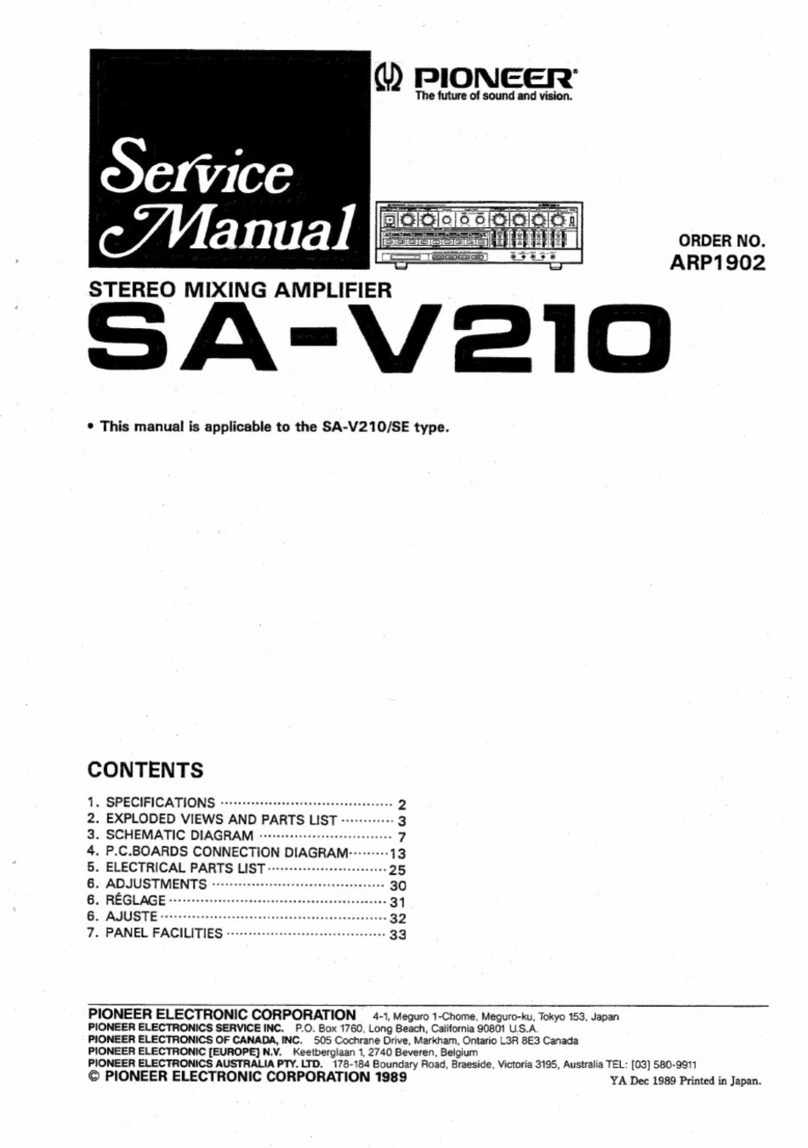
  9. Pioneer SA-V220 User manual

Pioneer SA-V220 User manual

dW)
PIONEER’
The
Art
of
Entertainment
SA=-V220
STEREO
MIXING
AMPLIFIER
AMPLIFICATEUR
DE
MIXAGE
STEREO
STEREO-MISCHVERSTARKER
AMPLIFICATORE
MIXER
STEREO
STEREO-MENG
VERSTERKER
MIXANDE
STEREOFORSTARKARE
AMPLIFICADOR
DE
MEZCLA
ESTEREO
ecerneeeaes
#3
E=sSssoood]
Thank
you
for
buying
this
Pioneer
product.
Please
read
through
these
operating
instructions
so
you
will
know
how
to
operate
your
model
properly.
After
you
have
finished
reading
the
instructions,
put
them
away
ina
safe
place
for
future
reference.
in
some
countries
or
regions,
the
shape
of
the
power
plug
and
power
outlet
may
sometimes
differ
from
that
shown
in
the
explanatory
drawings.
However,
the
method
of
connecting
and
operating
the
unit
is
the
same.
WARNING:
TO
PREVENT
FIRE
OR
SHOCK
HAZARD,
DO
NOT
EXPOSE
THIS
APPLIANCE
TO
RAIN
OR
MOISTURE.
LINE
VOLTAGE
SELECTOR
SWITCH
Only
multi-voltage
models
are
provided
with
this
switch.
U.S.
and
Canadian,
models
are
not
provided
with
this
switch.
Before
your
model
is
shipped
from
the
factory,
this
switch
is
set
to
the
power
requirements
of
the
destination,
nevertheless,
you
should
check
that
it
is
set
properly
before
plugging
the
power
cord
into
the
wall
outlet.
1.
Disconnect
the
power
cord.
2.
Use
amediurmsize
screwdriver.
3.
Insertthe
screwdriver
into
the
groove
on
the
voltage
selector
and
adjust
so
that
the
tip
of
the
arrow
points
to
the
voltage
value
of
your
area.
Operating
Instructions
Mode
d’emploi
Bedienungsanleitung
Istruzioni
per
I'uso
Gebruiksaanwijzing
Bruksanvisning
Manual
de
instrucciones
Nederlands
VOLTAGE
SELECTOI
eee
screwdriver
IMPORTANT
CAUTION
RISK
OF
ELECTRIC
SHOCK
DO
NOT
OPEN
The
lightning
flash
with
arrowhead,
within
an
equilateral
CAUTION:
triangle,
is
intended
to
alert
the
user
to
the
presence
of
uninsulated
‘dangerous
voltage”
within
the
product's
enclosure
that
may
be
of
sufficient
magnitude
to
constitute
a
risk
of
electric
shock
to
persons.
“This
product
complies
with
the
Radio
Interference
require-
ments
of
the
EC
(European
Community)
Directive
87/308/EEC.”
POWER-CORD
CAUTION
Handle
the
power
cord
by
the
plug.
Do
not
pull
out
the
plug
by
tugging
the
cord
and
never
touch
the
power
cord
when
your
hands
are
wet
as
this
could
cause
a
short
circuit
or
electric
shock.
Do
not
place
the
unit,
a
piece
of
furniture,
etc.,
on
the
power
cord,
or
pinch
the
cord.
Never
make
a
knot
in
the
cord
or
tie
it
with
other
cords.
The
power
cords
should
be
routed
such
that
they
are
not
likely
to
be
stepped
on.
A
damaged
power
cord
can
cause
fire
or
give
you
an
electrical
shock.
Check
the
power
cord
once
ina
while.
When
you
find
it
damaged,
ask
your
nearest
PIONEER
authorized
service
center
or
your
dealer
for
a
replacement.
BEFORE
CONNECTION...........c:c:cccssscereeeees
ry
4
CONNECTIONS
.......
Geebesviiee
sibdiaversesé
eubhuealtoos
Maubdleae
3
PANEL
FACILITIES
.............ccscscssssressssesessrenesseneeeees
OPERATION
........cccsssssssssssssenerestennesesaessnenerseeseses
BEFORE
CONNECTION
TO
PREVENT
THE
RISK
OF
ELECTRIC
SHOCK,
DO
NOT
REMOVE
COVER
(OR
BACK).
NO
USER-SERVICEABLE
PARTS
INSIDE.
REFER
SERVICING
TO
QUALIFIED
SERVICE
PERSONNEL.
CONTENTS
The
exclamation
point
within
an
equilateral
triangle
is
intended
to
alert
the
user
to
the
presence
of
important
operating
and
maintenance
(servicing)
instructions
in
the
literature
accompanying
the
appliance.
MAINTENANCE
OF
EXTERNAL
SURFACES
¢
Use
a
polishing
cloth
or
dry
cloth
to
wipe
off
dust
and
dirt.
©
When
the
surfaces
are
dirty,
wipe
with
a
soft
cloth
dipped
in
some
neutral
cleanser
diluted
five
or
six
times
with
water,
and
wrung
out
well,
and
then
wipe
again
with
a
dry
cloth.
Do
not
use
furniture
wax
or
cleaners.
e
Never
use
thinners,
benzine,
insecticide
sprays
or
other
chemicals
on
or
near
this
unit,
since
these
will
corrode
the
surface.
ENJOY
THE
ECHO
EFFECT
..............cscssseseeeseneeate
TROUBLESHOOTING
..........
vitisitassienn
Statue
eer
SPECIFICATIONS.
........
cece
seeseseesseeenteenes
a
dbaaseare
Connection
Precautions
¢Do
not
turn
the
stereo
mixing
amplifier
or
the
stereo
components
ON
before
all
connections
are
completed.
*
The
IN/OUT
terminals
of
the
stereo
mixing
amplifier
are
assigned
as
‘L"
for
the
left
channel
and
"R"
for
the
right
channel.
Be
sure
to
connect
to
the
correct
channel.
¢
Insert
the
connection
cables
correctly.
Improper
connection
may
result
in
no
sound
from
the
speakers
or
cause
background
noise.
2
<ARE1325>
En
LOCATION
Install
the
componentin
a
well
ventilated
location
where
it
will
not
be
exposed
to
high
temperature
or
humidity.
Do
not
install
the
component
in
a
location
which
is
exposed
to
direct
rays
of
the
sun,
or
near
to
hot
appliances
or
radiators.
Excessive
heat
can
adversely
affect
the
cabinet
and
internal
components.
Installation
of
the
component
in
a
damp
or
dusty
environment
may
result
in
malfunction
or
accident.
(Also
avoid
installation
near
cookers
etc.,
where
the
component
may
be
exposed
to
smoke
from
oil,
steam
or
heat.)
CONNECTIONS
Connection
of
Input
and
Output
Cords
¢
Connect
white
plug
to”
L
“
side
and
red
plug
to
*
R
"
side.
Make
sure
to
insert
them
securely.
¢
Insert
the
pin
plug
of
the
connecting
cords
securely.
incomplete
plugging
may
result
in
noise
or
insufficient
sound.
White
plug
|
;
L
@
,
IF.
Red
plug
Connection
of
Speaker
Cord
Strip
off
the
vinyl
coating
and
put
the
wire
ends
together.
iF
1omm
z
@
Loosen
the
screw.
@®
Insert
the
wires
into
the
hole.
@®
Tighten
the
screw
and
fasten
the
wires.
Impedance
of
Speaker
System
Speaker
systems
with
a
nominal
impedance
of
4
to
16
Q
can
be
used
when
systems
A
and
B
are
used
separately.
Use
nominal
impedance
of
8
to
32
Q
when
playing
both
systems
simultaneously.
To
use
ADAPTOR
jacks:
Remove
the
jumper
plug
when
connecting
a
graphic
equalizer
or
sound
processor
to
the
ADAPTOR
IN/OUT
jacks.
Store
the
jumper
plug
in
a
safe
place.
Do
not
install
it
onto
other
jacks.
¢
Be
sure
to
install
the
jumper
plug
when
you
are
not
using
the
ADAPTOR
jacks.
Output
Output
Pull
out
the
jumper
plug.
©
Donotinstall
the
jumper
plug
vertically.
Incorrectinstallation
may
cause
a
malfunction.
NOTES:
¢
When
using
only
the
speakers
with
a
separate
power
amplifier
connected
to
the
SA-V220:
Make
sure
to
set
the
MASTER
VOLUME
control
of
the
SA-V220
to
'0".
¢
When
using
speakers
with
both
the
SA-V220
and
a
separate
power
amplifier
connected
to
the
SA-V220:
Adjust
the
sound
volume
of
the
speaker
connected
to
the
SA-V220
using
the
MASTER
VOLUME
control
of
the
SA-V220.
¢
Adjust
the
sound
volume
of
the
other
speaker
connected
to
the
separate
power
amplifier
using
the
MASTER
VOLUME
control
of
the
power
amplifier.
3
<ARE1325>
En
CONNECTIONS
Be
sure
to
switch
the
power
of
the
stereo
mixing
amplifier
and
*
Becarefulto
avoid
wires
from
sticking
out
from
the
terminaland
the
stereo
component
ON
only
after
all
connections
of
stereo
touching
other
wires,
as
this
might
cause
malfunction.
system
are
completed.
LD
player
Stereo
preamplifier
To
connect
a
monophonic
amplifier.
To
connect
the
MIC
cable
from
the
system
rack
or
a
wireless
receiver.
To
an
AC
wall
socket.
©||©
(L)
(R)
Cassette
deck
Speaker
system
*
4
<ARE1325>
En
CONNECTIONS
CAUTION:
Do
not
connect
TV
or
Monitor
to
AC
OUTLET.
TV
camera
and
VCR
monitor
TV
Monitor
TV
Monitor
TV
Monitor
TV
Be
sure
to
insert
the
cord
completely
into
the
inlet.
To
an
AC
wall
socket.
eorecesenenmeccence
@
From
a
cable
broadcasting
as
device.
@
Connect
a
graphic
equalizer
or
a
sound
processor.
TV
camera
VCR
5
<ARE1325>
En
PANEL
FACILITIES
REAR
PANEL
@
MIC
INPUT
jacks
1,2
and
3
Connect
the
MIC
cable(s)
of
the
optional
video
rack.
The
MIC
INPUT
jacks
are
also
used
for
connection
to
the
optional
wireless
mic
receiver.
When
using
microphones
with
key
control
remote
switch
connected
to
MIC
1
and
2,
connect
the
control
cords
to
the
KEY
CONT
jacks.
If
a
microphone
is
connected
to
the
MIC
jack
on
the
front
panel,
front
input
has
priority.
NOTE:
*
Position
of
the
key
controller
may
change
by
connecting/
disconnecting
of
the
remote
plug.
in
such
a
case,
set
it
again
to
the
desired
position.
¢
For
the
key
control
function,
both
front
and
rear
inputs
are
effective.
@
VISUAL
INPUT
jacks
1
LASER
DISC
Connect
to
the
VIDEO
OUT
jack
of
the
LD
player.
2
VCR/CAMERA
Connect
to
the
VIDEO
OUTPUT
jack
of
the
VCR
or
TV
camera.
@
VISUAL
OUTPUT
jacks
TO
MONITOR
1-3
Jacks
for
connection
to
the
VIDEO
INPUT
jacks
of
TV
monitors
(maximum
three
monitors).
VCR/CAMERA
ONLY
Signals
input
to
the
“VCR/CAMERA"*
VISUAL
INPUT
jack
of
the
SA-V220
will
always
be
output.
By
connecting
to
a
TV
monitor,
you
can
monitor
a
VCR
or
video
camera.
6
<ARE1325>
En
@
AUDIO
OUTPUT
jacks
STEREO
These
jacks
are
used
to
output
the
Land
R
audio
signals
to
the
audio
input
jacks
(LASER
DISC,
VCR,
CABLE,
TAPE/AUX)
of
this
unit.
(excluding
MASTER
VOLUME
and
BALANCE
controls)
MONO
The
Land
R
audio
signals
input
to
the
audio
input
jacks
(LASER
DISC,
VCR,
CABLE,
TAPE/AUX)
always
appear
as
L
+
R
monaural.
©
SPEAKERS
terminals
Two
speaker
systems
(A
and
B)
can
be
connected.
For
details,
refer
to
"CONNECTIONS"
on
page
3.
NOTE:
Always
connect
the
plus
(+)
and
minus
(-)
wires
of
the
speakers
to
the
speaker
terminals
of
the
same
polarity.
A
polarity
error
can
cause
unnatural
sound.
©
VOLTAGE
SELECTOR
switch
@
VCR
VOLUME
control
Controls
the
volume
of
the
VCR
input
jacks
sound.
This
control
is
normally
centered
but
should
be
adjusted
in
accordance
with
the
volume
of
the
LASER
DISC.
VCR
SOURCE
SELECTOR
SENSITIVITY
switch
Switch
it
for
proper
operation
of
the
AUTO
SOURCE
SELECTOR
function
of
the
SA-V220.
For
the
AUTO
SOURCE
SELECTOR
function,
see
page
10.
M_:Normal
position
L
:s(When
no
LASER
DISC
signal
is
input.)
\f
"TAPE/AUX'
or
"CABLE"
terminal
is
automatically
selected
even
though
VCR
is
being
played,
set
to
this
position
“L"
to
select
VCR.
H_
(When
no
LASER
DISC
signal
is
input.)
If
"TAPE/AUX"
or
"CABLE"
is
not
selected
even
though
VCR
finishes
its
playback,
set
to
this
position
"H"
to
select
"TAPE/AUX’
or
"CABLE".
@
VCR
MODE
switch
This
switch
is
used
to
select
the
VCR
audio
modes
(MONO/
STEREO).
Connect
aVCR
with
monophonic
audio
output
either
to
“L"
or
“"R"
AUDIO
INPUT
jack
an
set
this
switch
to
"MONO".
(
TAPE/AUX
VOLUME
control
Controls
the
input
sound
level
of
devices
connected
to
the
TAPE/AUX
input
jacks.
This
control
is
normally
centered
but
should
be
adjusted
for
LASER
DISC.
()
TAPE/AUX
SOURCE
SELECTOR
SENSITIVITY
switch
Switch
it
for
proper
operation
of
the
AUTO
SOURCE
SELECTOR
function
of
the
SA-V220.
For
the
AUTO
SOURCE
SELECTOR
function,
see
page
10.
M_
:Normal
position
L
:(When
neither
LASER
DISC
nor
VCR
signal
is
input.)
if
"CABLE"
is
automatically
selected
even
though
"TAPE/
AUX"
signal
is
being
played,
set
to
this
position
“L"
to
select
"TAPE/AUX’.
H_
:(When
neither
LASER
DISC
nor
VCR
signal
is
input.)
lf
AUTO
INPUT
selector
remains
at
"TAPE/AUX"
even
though
TAPE/AUX
finishes
its
playback,
set
to
this
position
"H"
to
select
"CABLE".
(2
TAPE/AUX
MODE
switch
This
switch
is
used
to
select
audio
modes
(MONO/STEREO)
of
components
connected
to
the
TAPE/AUX
input
jacks.
Connect
a
component
with
monophonic
audio
output
either
to"L"
or
*R*
AUDIO
INPUT
jack
and
set
this
switch
to
"MONO".
@
CABLE
VOLUME
control
Controls
the
volume
of
the
CABLE
input
jacks
sound.
This
control
is
normally
centered
but
should
be
adjusted
in
accordance
with
the
volume
of
the
LASER
DISC.
PANEL
FACILITIES
(4
CABLE
MODE
switch
Changes
the
audio
mode
(MONO/STEREO)
of
cable
broadcasts.
For
mono
cable
broadcasts,
connect
to
either
the
"L"or"R"
channel
and
set
the
CABLE
MODE
switch
to
MONO.
@®
AUDIO
INPUT
jacks
LASER
DISC
Connect
to
the
AUDIO
jacks
of
a
LD
player.
VCR
,
Connect
to
the
AUDIO
OUT
jacks
of
a
VCR.
CABLE
Connect
sound
output
terminals
of
wire
broadcasting.
TAPE/AUX
Can
be
connected
to
the
PLAY
(OUTPUT)
jacks
of
a
cassette
deck
or
to
the
OUTPUT
jacks
of
other
audio
components.
6
TAPE
REC
jacks
Connect
to
the
REC
(INPUT)
jacks
of
a
cassette
deck.
Mic
mixing
recording
will
be
possible,
because
signals
processed
with
microphone
mixing
are
output.
NOTES:
*
Sound
of
CABLE
will
not
be
output
when
the
TAPE
REC
button
is
OFF.
*
Sound
of
TAPE/AUX
will
not
be
output
from
this
jack
in
any
case.
@
ADAPTOR
IN/OUT
jacks
Used
to
connect
a
graphic
equalizer
or
a
sound
processor.
The
ADAPTOR
IN/OUT
jacks
have
a
jumper
plug.
Install
the
jumper
plugs
when
you
do
not
use
these
jacks.
Otherwise,
there
will
be
no
sound
output.
4
GND
(Ground)
terminal
Always
ground
this
unit
to
prevent
electrical
shock
and
to
avoid
generating
interference
or
noise
in
other
equipment.
4
AC
INLET
jack
Connect
one
end
of
the
power
cord
to
here
and
the
other
end
to
an
AC
wall
socket.
If
you
are
going
to
be
away
from
home
for
a
long
period
of
time,
disconnect
the
unit
from
the
wall
socket.
<ARE1325>
En
PANEL
FACILITIES
FRONT
PANEL
QO
.
®@
STEREO
MIXING
AMPLIFIER
SA-V220
ALTO
HOUT
GELECTOR
vasea
osc)
va
JARO
cae
QGITAL
ECHO
PROFESSIONAL
SERIES
@
POWER
switch(
H
OFF/
=
ON)
Pressing
this
switch
turns
ON
the
power.
Pressing
this
switch
again
turns
OFF
the
power.
@
AUTO
INPUT
SELECTOR
indicators
This
unit
automatically
select
the
input
source
signals
with
priority
in
the
order
of
LASER
DISC,
VCR,
TAPE/AUX,
and
CABLE.
These
indicators
display
the
output
source
accordingly.
@
MUSIC
control
Controls
the
volume
of
equipments
connected
to
the
LASER
DISC,
VCR,
TAPE/AUX
and
CABLE
jacks
on
the
rear
panel.
Normally,
keep
the
MASTER
VOLUME
control
near
the
5-7
position
and
use
the
MUSIC
control
to
adjust
the
volume
of
the
music
source.
@
MASTER
VOLUME
control
Controls
the
volume
of
the
sound
from
the
speakers.
©
MIC
ECHO
control
Controls
the
echo
levels
for
microphones
1,2
and
3
simultaneously.
NOTE:
When
using
a
microphone,
the
original
sound
itself
is
processed
as
well
as
any
effect
sound
such
as an
echo,
which
is
added
to
the
original
sound.
When
using
an
effect
sound,
set
the
MIC
ECHO
control
to
'3"~"4".
©
MIC
volume
controls
(MIC
1,2
and
3)
To
adjust
the
respective
microphones
volume
level
against
the
music
source.
Normally,
keep
the
MASTER
VOLUME
control
near
the
5-7
position
and
use
the
MIC
controls
to
adjust
the
volumes.
8
<ARE1325>
En
Delele[e
[ele]
|
676
eG
@
KEY
CONTROL
buttons/indicators
Press
to
change
the
pitch
of
the
music
source.
A]
‘Changes
to
the
standard
pitch.
1-5
-A
maximum
raise
of
five
tones
above
the
setting
of
the
standard
key
is
possible
in
semitone-steps.
b1-b5
-Amaximumdecrease
of
five
tones
below
the
setting
of
the
standard
key
is
possible
in
semitone-steps.
NOTE:
No
key
change
is
possible
when
"CABLE"
has
been
selected
by
the
input
selector.
MIC
and
KEY
CONTROLLER
jacks
Three
microphones
can
be
connected
simultaneously.
When
using
a
microphone
with
key
control
switch,
connect
it
to
MIC
1
or
MIC
2
jack.
And
be
sure
to
connect
the
control
cable
to
the
KEY
CONTROLLER
jack.
NOTE:
KEY
CONTROLLER
jack
The
set
position
of
the
key
control
might
change
when
the
control
plug
is
connected
to
or
removed
from
the
KEY
CONTROLLER
jack.
In
such
a
case,
reset
to
the
desired
position.
MIC
jack
Whena
microphone
is
also
connected
toa
MIC
INPUT
jack
on
the
rear
panel,
the
microphone
connected
to
the
front
panel
has
priority.
Note
that
there
is
no
priority
order
with
the
key
control
function.
@
MIC
3
ECHO
switch
(
H
OFF/
=
ON)
This
switch
controls
only
the
echo
for
the
microphone
3
input.
@
MUSIC
TONE
control
(BASS/TREBLE)
Adjusts
the
tone
(bass/treble)
of
the
device
connected
to
the
_
LASER
DISC,
VCR,
CABLE
or
TAPE/AUX
jack
on
the
rear
panel.
@
MIC
TONE
control
(BASS/TREBLE)
Can
simultaneously
adjust
the
tone
of
MIC
1,2
and
3.
Adjusts
bass
and
treble.
@)
BALANCE
control
Adjusts
the
sound
balance
of
both
speakers.
PANEL
FACILITIES
jena
DELAY
O}
O}
TAPE
REC
Morr
ON
po
af
SHORT
LONG
@
ECHO
ADJUST
control
Varies
the
echo
characteristics
of
MIC
1,2
and
3.
REPEAT:Adjusts
the
timing
of
the
echo
(numberof
repetitions).
DELAY
-Adjusts
the
repetition
interval
of
the
echo.
©
TAPE
REC
button
Setting
this
button
to
ON
allows
you
to
record
cable
broadcasts.
Set
the
button
to
OFF
when
you
are
not
recording
cable
broadcasting
programs.
NOTE:
TAPE/AUX
will
not
be
selected
by
AUTO
INPUT
SELECTOR
when
this
button
is
ON.
<ARE1325>
En
OPERATION
eect
.
Turn
the
power
ON
to
the
SA-V220
and
other
components.
When
using
an
LD
player,
turn
on
the
TV
monitor.
2.
Connect
the
microphone(s)
to
the
MIC
jack(s).
3.
Set
the
MASTER
VOLUME
control
as
desired
(e.g.
set
to
5-7).
4.
Start
playback.
Adjust
the
volume
level
with
the
MUSIC
control
and
speaker
balance
with
the
BALANCE
control.
5.
Speak
or
sing
into
the
microphone
and
adjust
the
volume
level
with
the
MIC
volume
control.
ENJOY
THE
ECHO
EFFECT
6.
Adjust
the
sound
with
the
MUSIC
TONE
controls,
ECHO
ADJUST
controls,
MIC
TONE
controls,
and
MIC
ECHO
control
as
desired.
7.
Select
the
desired
key
with
the
KEY
CONTROL
buttons.
AUTO
SOURCE
SELECTOR
The
SA-V220
automatically
selects
and
outputs
all
input
signals
according
to
the
following
priority.
1.LASER
DISC
2.VCR
3.TAPE/AUX
4.CABLE
The
input
sensitivity
of
VCR
and
TAPE/AUX
can
be
changed
by
the
SOURCE
SELECTOR
SENSITIVITY
switch
on
the
rear
panel.
Automatic
output
switching
of
TV
monitor
When
the
LD
player
is
in
stop
mode,
VIDEO
signals
from
VISUAL
INPUT
jack
2
(VCR/CAMERA)
will
be
output
from
the
VISUAL
OUTPUT
jacks
1,2
and
3
to
the
monitor.
Fade-in
function
for
cable
When
the
SA-V220
is
switched
from
LASER
DISC,
VCR
or
TAPE/AUX
mode
to
CABLE
mode,
the
fade-in
circuit
is
activated
and
the
volume
level
gradually
increases
to
the
level
that
has
been
set
by
the
MASTER
VOLUME
control
after
approx.
2
to
8
seconds.
Adjustment
of
the
Microphone
Echo
Volume
An
echo
effect
makes
you
feel
as
if
you
are
singing
well,
just
like
when
you
are
humming
in
the
bathroom.
With
the
amplifier,
the
echo
can
be
simultaneously
applied
to
MIC
1,2
and
3.
The
echo
volume
can
be
adjusted
with
the
MIC
ECHO
control.
MIC
3
can
be
turned
on/off
using
the
switch.
Echo
Adjustment
Echo
can
be
adjusted
by
the
following:
REPEAT
Changes
the
echo
cycle
to
enhance
the
echo
effect.
Adjust
to
a
shorter
echo
cycle
for
tunes
with
a
quick
tempo.
Adjust
to
a
longer
echo
cycle
for
tunes
with
a
slow
tempo.
DELAY
Changes
the
echo
intervals
to
enhance
the
echo
effect.
Adjust
the
intervals
according
to
the
tempo
of
the
tune.
Adjust
to
the
desired
echo
effect
by
using
the
REPEAT
and
DELAY
controls.
10
<ARE1325>
En
To
Maximize
the
Echo
Effect
for
Karaoke
(Sing-
Along)
Set
the
sound
volume
of
the
music
slightly
lower
than
the
vocal.
This
will
improve
the
mixing
balance
and
maximize
the
echo
effect.
TROUBLESHOOTING
Incorrectoperations
are
often
mistaken
for
trouble
and
malfunctions.
If
you
think
that
there
is
something
wrong
with
this
component,
check
the
points
below.
Sometimes
the
trouble
may
lie
in
another
component.
Investigate
the
other
components
and
electrical
appliances
being
used.
If
the
trouble
cannot
be
rectified
even
after
exercising
the
checks
listed
below,
ask
your
nearest
PIONEER
authorized
service
center
or
your
dealer
to
carry
out
repair
work.
No
sound
from
both
or
either
|
*
Power
cord
is
unplugged.
¢
Connect
the
power
cord.
speaker.
¢
BALANCE
control
is
set
to
max.
right
or
left
|
¢
Set
the
control
to
center
position.
position.
¢
Either
plug
of
the
speaker
cord
is
disconnected.
|
¢
Connect
the
plug
securely.
Microphone
mixing
does
not
|
¢
Microphone
is
incompletely
plugged.
operate.
e
MIC
volume
control
is
set
to
minimum.
"TAPE/AUX"
and
"CABLE"
of
AUTO
|
®
TAPE
REC
button
turns
OFF.
INPUT
SELECTOR
indicators
are
switched
alternately
before
recording
the
wire
broadcasting.
SPECIFICATIONS
e
Plug
the
microphone
completely
into
the
terminal.
e
Adjust
with
the
MIC
volume
control.
e
TAPE
REC
button
turns
ON.
Abnormal
functioning
of
this
unit
may
be
caused
by
lightning,
static
electricity,
or
other
external
interference.
To
restore
normal
operation,
turn
the
power
off
and
then
on
again,
or
unplug
the
AC
power
cord
and
then
plug
it
in
again.
DIN
Continuous
power
output
(both
channels
driven
at
1
kHz)
T.H.D.
1.0
%,
8
Q
viccccccssssssscsesseecsetsnseesseees
75W+75W
T.H.D.
1.0%,
4
OQ
viccccscccsssessessecssersreeeteeees
120
W
+
120
W
Total
harmonic
distortion
(AUX
IN,
1
KHz,
60
W,
80)
wooo
erect
renee
0.03%
Input
Terminal
(Sensitivity/Impedance)
Audio
MI
Ge
os
eitiesctsentnes
edd
can
tia
eed
2.5
mV/25kQ
VCR,
TAPE/AUX
.....cccccccccsesscseesectetneesteeteees
75
mV/50
kQ
LASER
DISC,
CABLE
0.0...
cceceseeereereeeees
150
mV/50
k
Q
ADAPTOR
iNput.........eeeeseeeseeseseeeseeeseeaes
150
mV/50
kQ
Video
LASER
DISC,
VCR/CAMERA
..........-:eeeeeees
1
Vp-p/75Q
Output
Terminal
(Output
level/Output
impedance)
Audio
AUDIO
OUTPUT
(STEREO,
MONO)
..............
1V/2.2kQ
TAPE
REG
sidesnccneidncectereenidcccdeetss
150
mV/4.4
kQ
ADAPTOR:
extvigtean
teotecenthbdstira
nies
150
mV/2.2
kQ
Video
MONITOR,
VCR/CAMERA...........:::::eeerceeees
1
Vp-p/75
Q
Speakers
Terminal
AO6
Bi
iind
ai
ce
beissessvasveeei
pceck
iota
Blah
nde
ateanse
teas
4to16Q
PONG
Besse
etichedseiremil
tetera
eevee
8
to
32
Q
Frequency
Response
MIG
bcs
atest
Metesaanatienentics
100
Hz
to
10
kHz
“3
dB
LASER
DISC,
CABLE,
VCR,
TAPE/AUX
Laide
hirees
edie
BA
Ge
Sette
Tes
At
eet
Sy
10Hz
to
30
kHz
“3.
dB
Tone
Control
(Music/Mic)
BASS.
bs,
castectie.dSes
dena
“2
dB/
dB
(100
Hz)
TREBLE
2y-.8
is
eee
%
dB/
44
dB
(10
kHz)
Echo
delay
time/decay
time
..130
to
210
msec
/0.6
-
2.5
sec
Key
Control
Range
.....
2.5
musical
intervals
(11
positions)
Signal-to-Noise
Ratio
(DIN,
continuous
power
/
50mW)
MIG
sits
scien
amides
deci
weed
orl
ade.
56
dB/
55
dB
LASER
DISC,
CABLE,
VCR,
TAPE/AUX
.........
64
dB/
56
dB
Power
Supply/Miscellaneous
Power
requirements
.......
AC
110~115/120/220~230/240
V
(switchable),
50/60
Hz
POWEF
CONSUMPTION
0.00.0...
cece
cee
eeee
eee
erteeene
teeter
ee
500
W
Dimensions
..............005
420
(W)
X
130
(H)
X
440
(D)
mm
Weight
(without
package)
..........ceseceeceesseeneeees
13.0
kg
Accessories
AUdIOsCONM
senshi
ohntne
ene
s
1
POWER
COPD
sie.
cs2025
aes
itie
Sete
tev
a
eee
nds
1
Operating
instructions...
ce
eeepeeeee
ste
ee
es
eeeeeteeeeeens
1
NOTE:
Specifications
and
design
subject
to
possible
modification
without
notice,
due
to
improvements.
Published
by
Pioneer
Electronic
Corporation.
Copyright
©
1994
Pioneer
Electronic
Corporation,
All
rights
reserved.
11
<ARE1325>
En

Other Pioneer Amplifier manuals

Pioneer GM-X404 User manual

Pioneer

Pioneer GM-X404 User manual

Pioneer GM-202 User manual

Pioneer

Pioneer GM-202 User manual

Pioneer D-23 User manual

Pioneer

Pioneer D-23 User manual

Pioneer M-73HEZ User manual

Pioneer

Pioneer M-73HEZ User manual

Pioneer GM5400T - Bridgeable Amplifier User manual

Pioneer

Pioneer GM5400T - Bridgeable Amplifier User manual

Pioneer VSA-E08 User manual

Pioneer

Pioneer VSA-E08 User manual

Pioneer SA-7500 User manual

Pioneer

Pioneer SA-7500 User manual

Pioneer KEH-P5000 User manual

Pioneer

Pioneer KEH-P5000 User manual

Pioneer SA-9900 User manual

Pioneer

Pioneer SA-9900 User manual

Pioneer A9 User manual

Pioneer

Pioneer A9 User manual

Pioneer Elite SX-A6MK2-K User manual

Pioneer

Pioneer Elite SX-A6MK2-K User manual

Pioneer VSA-LX805 Manual

Pioneer

Pioneer VSA-LX805 Manual

Pioneer QM-800A User manual

Pioneer

Pioneer QM-800A User manual

Pioneer GM-D1004 User manual

Pioneer

Pioneer GM-D1004 User manual

Pioneer M-F10 User manual

Pioneer

Pioneer M-F10 User manual

Pioneer M-L11 User manual

Pioneer

Pioneer M-L11 User manual

Pioneer GM-320T User manual

Pioneer

Pioneer GM-320T User manual

Pioneer GM-6100F User manual

Pioneer

Pioneer GM-6100F User manual

Pioneer GM-202 User manual

Pioneer

Pioneer GM-202 User manual

Pioneer GM-A5602 User manual

Pioneer

Pioneer GM-A5602 User manual

Pioneer A-676 User manual

Pioneer

Pioneer A-676 User manual

Pioneer ND-G500XS User manual

Pioneer

Pioneer ND-G500XS User manual

Pioneer A-A9-J User manual

Pioneer

Pioneer A-A9-J User manual

Pioneer VSP-200 User manual

Pioneer

Pioneer VSP-200 User manual

Popular Amplifier manuals by other brands

Monacor PA-1120 instruction manual

Monacor

Monacor PA-1120 instruction manual

Constellation Pictor owner's manual

Constellation

Constellation Pictor owner's manual

NAD M10 V2 owner's manual

NAD

NAD M10 V2 owner's manual

Extron electronics Fiber Optics Fox 4G DA8 user manual

Extron electronics

Extron electronics Fiber Optics Fox 4G DA8 user manual

Musical Fidelity M8700m Instructions for use

Musical Fidelity

Musical Fidelity M8700m Instructions for use

Vibe BASS1-V1 instruction manual

Vibe

Vibe BASS1-V1 instruction manual

Fender '57 Deluxe owner's manual

Fender

Fender '57 Deluxe owner's manual

Pace PX 200BL Manual for installation

Pace

Pace PX 200BL Manual for installation

JBL 6230 user manual

JBL

JBL 6230 user manual

Carson SA-430 Installation and operating instructions

Carson

Carson SA-430 Installation and operating instructions

Stagg KBA 40 user manual

Stagg

Stagg KBA 40 user manual

QSC USA Series user manual

QSC

QSC USA Series user manual

Redgum RGH900 operating instructions

Redgum

Redgum RGH900 operating instructions

McIntosh C2200 owner's manual

McIntosh

McIntosh C2200 owner's manual

Rotel RMB-100 owner's manual

Rotel

Rotel RMB-100 owner's manual

Omron K7L-AT50 quick start guide

Omron

Omron K7L-AT50 quick start guide

Audio Research D400 owner's manual

Audio Research

Audio Research D400 owner's manual

Messotron MBI 46.12 Series operating instructions

Messotron

Messotron MBI 46.12 Series operating instructions

manuals.online logo
manuals.online logoBrands
  • About & Mission
  • Contact us
  • Privacy Policy
  • Terms and Conditions

Copyright 2025 Manuals.Online. All Rights Reserved.