manuals.online logo
Brands
  1. Home
  2. •
  3. Brands
  4. •
  5. Pioneer
  6. •
  7. Cassette Player
  8. •
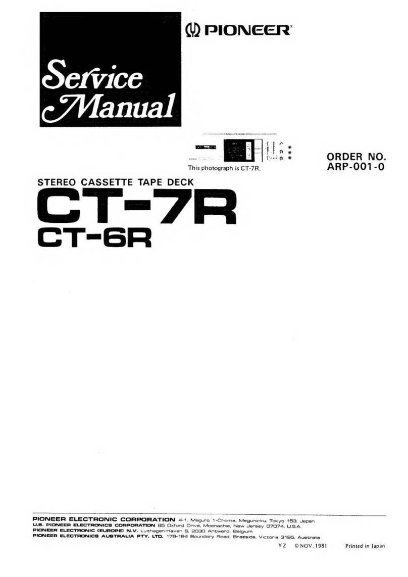
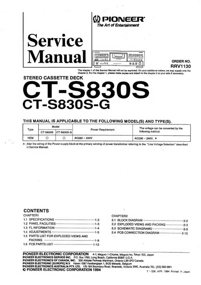
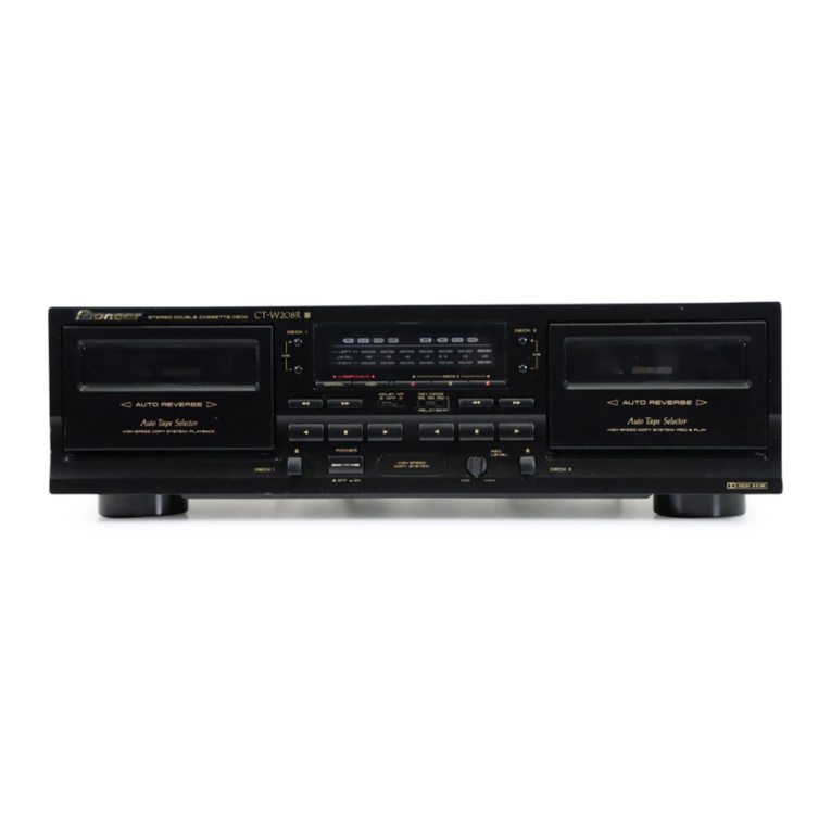
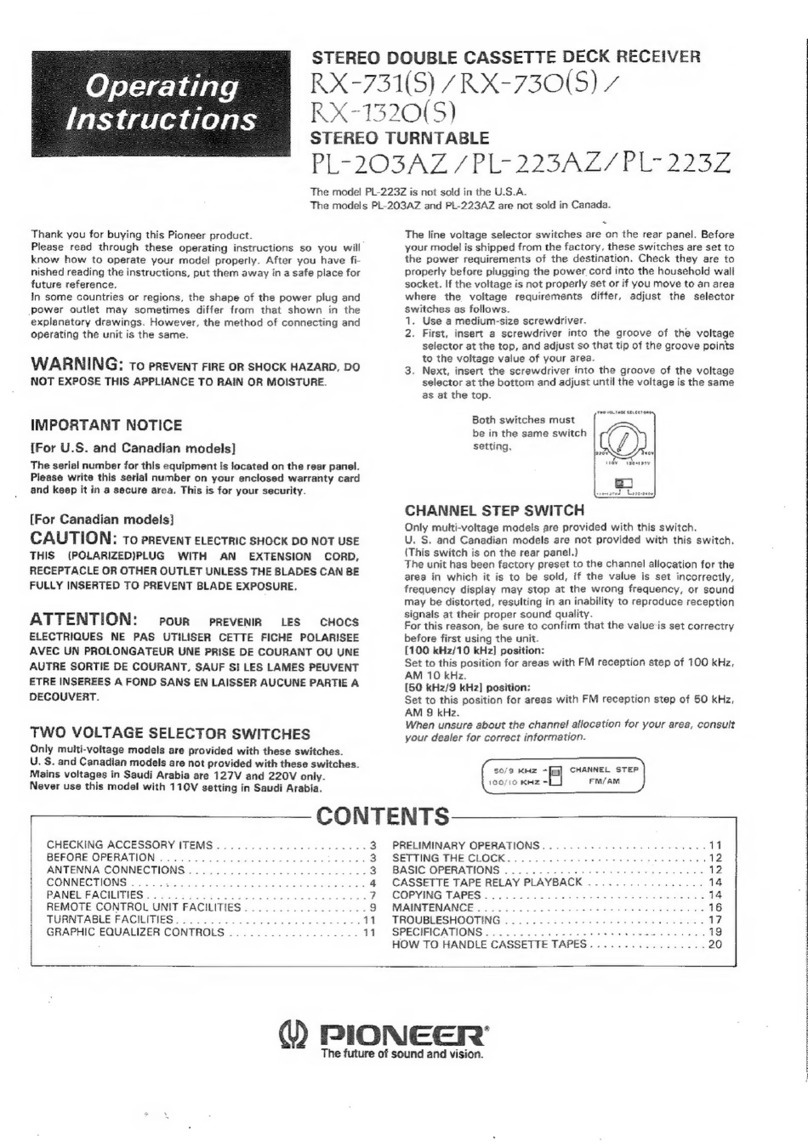
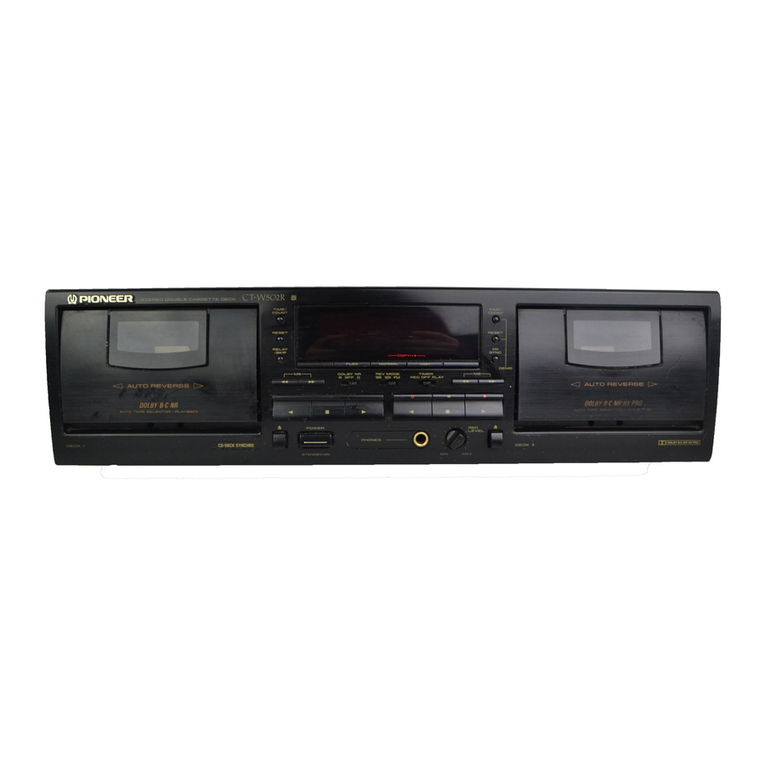
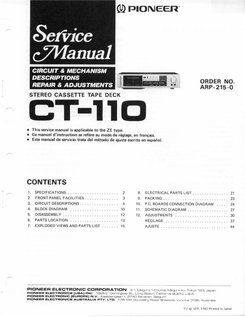
  9. Pioneer ARP-006-O User manual

Pioneer ARP-006-O User manual

c)rrIoNEER'
ORDER
NO.
ARP-OO6-O
STEREOCASSETTE
DECK
MODEL
CT-X5OCOMESIN FIVE
VERSIONS
DISTINGUISHED
AS
FOLLOWS:
o Thisservice
manual
is applicable
to the KU type. Forservicing
of the othertypes,
please
refer
to the
additional
servicemanual.
o Ce
manuel
d'instruction
se
refère
au
mode
deréglage,enfrançais.
o Este
manualde
servicio
tratadelmétodo
de
ajuste
escritoenespafiol.
1.
2.
3.
4.
5.
6.
7.
2
3
4
5
7
15
"17
8.
9.
10.
11.
12.
P.C.BOARDS
CONNECTION
DIAGRAM
SHEMATIC
DIAGRAM
ELECTRICAL
PARTS
LIST
PACKING
ADJUSTMENT.
REGLAGE
ADJUSTE
Type Voltago Remarks
KU 12OV
only U.S.A model
r{E 22OY
and24OV
(Switchablel Europe model
HB 22OY
and240V (Switchabte) U.K.
model
D12OV,22OV
and
240V (Switchabtel General
export model
D/G 1
2OV, 22OV and 24O (Switchablel U.S.military model
CONTENTS
SPECIFICATIONS
FRONT
PANELFACI
LITIES
.
DISASSEMBLY
PARTS
LOCATION
CIRCUITDESCRIPTIONS.
BLOCKDIAGRAM
EXPLODED
VlEWS
AND
PARTS
LIST
24
27
30
32
33
40
47
PfONEEFI ELECTFICINIC CC|FIPCIFIATIEIN 4-1. .v'esuro I -chome. Meeuno-ku. Tokyo j s3. Jêpân
U.a. F|CTNICF| ILICTF|CINICa CCIF|PCIFIAI|CIN BS Oxro.d D.rve. Moonêchre. New Jensev O7O74. US A
FlGlNlll| CLCCTFICINIC (É9F|C!FE! N.\/. LurEhegen-Hêven g, 2OSO Ancwenp. E}etgrum
FfClNllF lLlCIFlClJ\|lCa AUaTFALIA F1Y. L1Ct. 17A-1e4 Eloundê.v Ftoêd, BnBèsrcte. VrcEoFrâ 31S8. AusE.Êtrs
FZ
O J
ULY 1981
Printed
in
Japan
All manuals and user guides at all-guides.com
all-guides.com
5. CIRCUIT
DESCRIPTIONS
The main circuit configuration is outlined in the
block diagram
on page
15.
5.1 SIGNALPATH
Recording
Mode
The input signal from LINE INPUT is passed
via
the INPUT volumecontrol, flat amplifier andMpX
filter before being applied to the Dolby NR circuit.
The Doly NR circuit output is then applied to
the recording amplifier equalizer where the fre-
quency response
is regulated
according
to the type
of tape being used before finally being applied
to the recording
head.
Playback
Mode
The playback head output signalis applied to
the playback equalizer (gain 5B.2dB) where the
frequency response is corrected according to the
type of tape being used. Following this, the signal
is passed via the MPX filter to the Dolby NR
circuit, and
then
via
the REC/PB
switch
(HA1200b
elechonic switch) and MUTE switch (HA12006
electronic switch) to the LINE OUTPUT as the
playback output signal.
5.2 CONTROLCIRCUIT
TheCT-X50
contuol
circuit (outlined
in Fig.5-1)
features
alogic IC (8A843) for control of mechani-
cal drive by feather-touch switch operations. The
84843 pin layout is shown in Fig. 5-1 and the
input/output::i^:":: :,t:: t""1"-
Fû Sî6F FF MÊrio ru PA,SE -REc cNo
Fig.
5-1 Pin
arrangementof 8A843
Power-Assist
Mechanism
Before describing circuit operations during each
operational mode, the basic principles of the
power-assist
mechanism will beexplained.
Gearreturnspring Flywheel
assembly
Gearlever Stopper
Fig.
S-2
STOp
mode
o Stop Mode
1. The cam gearis positioned asshown in Fig. b-2.
o Stop Mode to Play Mode (Figs. b-4, b-b, b-6)
2. WhensolenoidP (pinch solenoid)
isactivatede,
the camgear
stopper
isreleased
O.
3. The operating lever is then forced down
(direction @) bV the operating lever return
spring, and because
of the shapeof the cam,
the cam gear starts to turn in direction @.
4. As the cam gear rotates in direction O . it
engages
the capstangear
@.
Leverspring
Input
signal Output Outputmode
U'T F O.REW O_RE
CO-PAU
SE O-PLAY
STOP LLLLLSTOP mode
FF HHFF mode
nLHLLREW mode
PLAY LLLLHPLAY mode
PAUSE LLLLHLPAUSE mode
REC/PLAY LHLHREC/PLAY mode
BEC/P_A_USE LLHHLREC/PAUSE
mode
Fig.
5-3
Input/output
truthtable
All manuals and user guides at all-guides.com
Gearreturnspring Play
Mode
to Stop
Mode
(Fig.5-7)
7. lilhen switching to stop mode, solenoid P is
deactivated
(in direction (D ) andthecam
gear
stopper released
(D. The cam gear
rotatesto
the stopper
position(@, O), andthe operat-
ing leveris lowered((D) bV
theoperating
lever
return spring,
therebyrestoringthemechanism
to theoriginal
stopmodestatus.
1 Gear
return
spring
I Camq
Flywheel
assembly
Capstan
Lever
spring
assembly
Solenoid
Po
Fig.
5-4 STOP
+ PLAY modeI
5. Once the cam gear engages
the capstan gear,
the motor and flywheel rotational momentum
continue to drive the cam gear@ until the
stopper reaches the PLAY position 0). ln
this position, the operating lever is pushed up
@due to the shapeof the cam.
6. At the same time, the operating lever shaft
is raised 0, thereby pushing the HB drive
spring attached to the head base upwards to
force the head baseinto the PLAY position.
And since the pinch pressure spring is also
elevated, the pinch roller is pressed against
the capstanfor start of play.
Flywheel
assembly
I
Cam
gear
Gear
lever
Lever
Solenoid
p assembly
Fig.
5-7 PLAY + STOP
mode
TapeTransport ModeSwitching
Pins 1, 2, 3 and 5 of IC402 (8A834) are the
input pins for PLAY, STOP,FF and REW. When
any pin is switched to L level, the tape deck
is switched to the conesponding transport mode.
For example, when 52 and S3 are switched on,
pins 1 and 2 of. IC404 are switched to L level,
resulting in the OR gate output pin 3 also being
switched to L level. This is followed by pin 1
of.1C402 being switched to L level,thereby switch-
ing the deck to play mode. Likewise, SB and 54
are switched on for fast forward mode, 52 and Sb
for rewind mode, and 54 and 55 for stop mode.
I
; Gearreturn
spring
I Cam
gear
SolenoidP
Solenoid
P
El
Gear
lever
Fig.
5-5 STOP
-' PLAYmode
tl
return
spring
Gearlever
Leverspring
Stooær
Q
o
f615t4t3t2{tto9
tc4o2 8A843
1234567
Fig.
5-8 Tape
transportmode
switching
Fig.
5-G
STOP-+
PLAYmodelll
All manuals and user guides at all-guides.com
J---_1_
U
J.--1/.-
ft
lltl
5.3 MUTING
CIRCUIT
Muting Gate
The LINE OUTPUT muting gateis incotporated
in IC401 (H412006), the output being muted
when pin 15 of this IC is at L level and pn 2 at
H level.
Pin 15 is connected to the PLAY output of the
operating mode control IC (8A843) and is switch-
ed to H level only during playback mode. +B is
applied to pin 2 vn R478 and,
R477, and the pin
is kept at H level except when Q426 is turned on
during recording mode. In this way, the line output
is muted during fast forward, rewind, stop and
play pause modes, and cancelled during playback,
recording and recording pause
modes.
Fig.
5-12
LINEOUTPUTmutins
The recording amplifier input muting gate is
gloundconnected by transistors
(Q103 and Q104).
The basesof these hansistors areconnected to pin
2 of HA12006 via R145, R143, R428, D427,
D429 and R477, thereby enabling muting to be
cancelled during recording mode. fhrring rec mute
mode, however, these bansistors are turned on,
resutling in the recording of blank sectionsof tape.
BECAMP
D4æ D427
2.
3.
r
':
L
sroP1- vs --J*pg1y
lC4O2Pin 14
Pinchsolenoid
Head base
MSsolenoid
FF solenoid
1C403
Pin6
1C403
PinS
Fig.
5-10 MSoperation
timingchart
Auto-Stop
Circuit
This circuit is used to switch the mechanical
driveconbol IC (BA843)to stopmodewhen
tape
transportstops
(see
Fig.5-11).A photo-intemrpter
is used
for tape
transportdetection,
andtherotary
blademechanismusedto intemrpt the light beam
iscoupled
to thetake-upreelby belt.
During
TapeTransport
1. Q401 is turned on and off repeatedlyby the
photointernrpter output, resulting in C403
being chargedup and discharged
againin re-
peated
cycles.
When
TapeTransport
Stops
When the take-up reel stops at the end of the
tape, Q401 ceases
switching on and off due to
the lossof the photo-intemrpter output.
With a current being passed
from +B to C4O3
via R405 and R406, C403 is charged up and
the Q402 base potential increases, resulting
in Q402 being turned off. Q403 isthus turned
on and pin 2 (STOP) of.tC402 is switched to
L level, thereby switching the deck to stop
mode.
IC402 (O-PLAY,
(
4a843' to
(o-REC)
c402
cr03
F405
i
\
i'i
J
+B
(12V1
2
(
STOP'
I
c{02
t4
{5
o{0r
t2
FiS.
+t 1Auto-stop
circuit Fig.
5-13 REC
AMPmuting
All manuals and user guides at all-guides.com
a
Muting at Start of ptayback Mode (Stop 1s p;6r_
back Model)
When the tape deck
mode from stop mode,
mode control IC (BAg4i
level, and pin 1 of IC4(
temporarily to H level .4 is fully charged up).
cancellation of muting-at
>de is dêtermined by tt u
100ms) of C4}6connect-
is
arso
added
due
to
ii3î;lil"Tâ1,r.îiï,ii,l#i
Consequenfly,
line outplî *rù;;l; cancelled
approximately0.6sec
lfter swidilg t"optayuactc
*:dg, therebyeliminating
tt " slro"t"nài*u
g"rro"t_
edwhen
thehead
nrakes
"ir"t"J *itrri[" ,"o".
5.4 RECORDTNG
MUTING
\qf3
IEC/PLA1 O-REC I O.PLAY
lrlH
Mutingat Start of Recording
Mode(Stopto Re_
cording
Mode)
C438 connected
to pin g of HAL2006 is a
timing capacitor
usedto regubtÀtrre
lperationat
timing of the head
_switch
(the rà"oraing signal
shorting
relayRyB01 connectea
to-pin 6). When
switching to recordingmode frorn-riop mode,
9jl8 i: charged
up,anâ
pin 6 switàhed
from L ro
n revelonce the capacitorhasbeencharged
up.
ïVhile this C4Bg is--being
"fr*eàJ "p (approx.
200ms),
the LINE OUTPU"T
i, *-,itua.
ôat ismut_
ing is cancelled
after a delayof abàut 200ms,
thereby
eliminating
switching
"tir". ---
Fis.5-14
Fig.
5-15 Muting
atstart
of recording
FiS.
S-t0
Recording
muting
This function is employed in preparing blank
sections
of unrecor.l-eà
iupu ,"ffi"a for MS
(automatic
location
.ot.
stari'ort."""]]bi"" e e426
Q427 arc both on durir ------l' I
99t-di"g amplifier input
(41.03 and e104) are
remrans unmuted. If Si
switched on, e10B and (
passed via SB, D426.
Q103 (Q104).The .u"o*
attenuated, and tape har
any signal being reco_rded.
At the sametime, +B i6
lJropur:g9
viaSB,
R480
and
isorôz b e426,
jf,i"glvlet'tinguprhe
REC
Mu-T-E-i;icator
lamp
(LED507).
BEC
AMP
lc 4Dt
(HAI2OO6)
Muting
atstart
of playback
All manuals and user guides at all-guides.com
4. PARTS LOCATION
Front
PanelView
KnobA (TlMERl
RAC-170
Eject knob
RAC-164
NOTES:
o Parts without part number cannot be supplied.
o The ;i. marh found on some component parts indicates the importance of the
safety factor of the part, Therefore, when replacing, besure to use parts of identical
designation,
o For your Parts Stoch Control, the fast mouing items are indicated with the
marks ** and t
** GENERALLY MOVES FASTER THAN *
This classification shall be adjusted by each distributor becauseit depends on model
number, temperature, humidity, e
tc.
Bonnet
RNA-549
B
(REC}
RAC-21
5
f
I
)
nction knob
RAC-2|3
KnobD (DOLBY
NR)
RAC-l68
C
(REC
MUTE)
RAC-216
Knob
A (PAUSE)
RAC-214
t t Push
switch
RSGO88
Function switch assembly
* * Push
switch
RSG-I
14
* * Pinch
arm assembly
R8H-760
l\ Strainretief
REC-272
A Coro
RDG.O22
(BDGO30)
* t Door assembly
RX8.594
Power knob
RAC-163
Knob C (MUSIC
SEARCH)
RAC-172
Knob
B
(REC/PLAY)
RAC-171
FrontViewwith FrontPanel
Removed
Counter
RAW.159
Cassetteplate assembly
RXX-325
* Erase
head
RPB-085
** REC/PB
head
RPBO84
Rear
Panel
View
Terminal
(LINE)
RKB-o18
* Variable resistor
RCV-093
Pin
jack
RKN071
5
All manuals and user guides at all-guides.com
all-guides.com
TopViewwith Bonnet
Remoræd
I
I * Motor
assembly
RXM-076
TopView
with Bonnet
Removed
ll
Connector
assembly
4P
BKP.356
Connector assembly
2P
[ * Powertransformer
(120V1
RTT-238
* * Capstan belt
REB41.I
Flywheel assembly
RX8-358
r
Motherassembly
connectorassembly
3P
RKP.269
Connector
assembly3P
RKP.27O
trolassembly
Fort sencer
assembly
I
{
Timer
switch
assembly
All manuals and user guides at all-guides.com
Whenthe Pornær
is Switched on (SeeFig. 5-91
When the power is switched on, +B is passed
via
C4O4 and R415 to Q40G, being turned on for
about 1.5 to 2.5 seconds
(until C404isfully charg-
ed). This results in pin 2 (STOP) of IC402 being
switched to L level, thereby ensuringthat the deck
is orginally in stop mode. If any other switch is
pressed during this initial brief period, the deck
will remain in stop mode. +B will, however, be
applied to the capstan motor and the motor will
startup.
Playback Mode
When the PLAY switch (S2/SB)
ispressed,
pin 1
(PIÂY) of.tC4O2 is switched to L level and pin 12
(O-PLAY) to H level. +82 is thereby passed
via
F"423 and R424 to Q410, rezulting in this transist-
or being tumed on. The pinch solenoid SOL is
consequently activated and playback mode com_
menced(see
Power.Assist
Mechanism).
Recording
Mode
1. Iilhen a cassette half with the erasurepreven-
tion tabs intact is loaded into the deck (result-
ing in the erasureprevention switch S10 being
switched to the NO HOLE position) and SZ
switched on, pin 10 (O-REC) and pin 12
(0-PLAY) of.IC4O2
switched
to H level.
2. The pin 10 output is applied to the base of
Q426 vira
R481. With e426 turned on, pin 2
(REC signal input) of. IC4OI is switched to L
level. And since pin 12 is at H level, pin 1b
(PLAY signal input) of IC401 is switched to
H level resulting in pin 6 (headswitch) and pin
16 (recording/playback switch) of IC401 also
being switched to H level. The recording input
shorting relay RY301 in the record/playback
head circuit is openedand the playback output
shorting transistor Q101 is tumed on (thereby
switchingthe head
to recordingmode).
3. With'pin 10 of IC4O2
andthe playback output
shorting transistor Q301 is turned on and the
biasoscillator activated.
If a cassettehalf without the erasure preven_
tion tabs is loaded, S10 is switched to the
HOLE position, resulting in pin g (À-R) of
IC4O2 being switched to L level. In this state,
the tape deck will not be switched to recording
mode when pin Z (EE-C)
is switched to L level.
Fast Forward Mode
When the FF switch (Sg/S4) is pressed,
pin 1b
(0-FF) of.1C402 is switched to H level, reiulting
in +32 beingpassed,
to e40T via R4LT and R41g.
And once Q407 is tumed on, the FF solenoid
is activated to start fast forward mode.
Rewind Mode
When the REIV switch (S2lSb) is pressed,pin
13 (O-REW\ of.lC4O2 is switched to H level,result-
ing in +82 being passed to Q408 via R420 and
R42L, thereby turning Q408 on to activate the
REW solenoid for start of rewind mode.
Time Playback
Mode
Tape playbaek is started automatically at the
time set by the timer.
1. I{hen the power is switched on with the
TIMER switch S11 on and S12 set
to play, +B
is immediately passedto Q411 via C406 and
È426, thereby tuming Q411 on for about Bto
5 seconds (until C406 is fully charged). In
addition, +B is applied to Q406 via C404 and
R415, resulting in Q406 being turned on for
about 1.5 to 2 seconds(until C404 is fully
charged). As a rezult, pin 1 (Pf,Ây) and pin 2
(STOP) of.IC OZareswitched to L ievel. -
2. lflhile pin 2 remains at L level, stop mode has
priority over all other modes, and pin 12
(O-PLAY) of. 1C402 is switched to L level.
REC/PB head
ry o!0.+B3
osc
BLOCK
All manuals and user guides at all-guides.com
3. Q406 is turned off once C404 has been fully
charged up, resulting in pin 2 of.l0402 beng
switched to H level (L + H). Since Q411 is
on at this time, pin 1 of ICAOZ will be at L
level, and pn 72 will be swiôched to H level
(L - H). Q410 will thereby be turned on,
and the pinch solenoid SOL activated as des-
cribed abovefor playback mode.
Timer Recording
Mode
The tape deck is started up automatically in
recording mode at the time set by the timer.
1. \[hen the power is switched on with the
TIMER switch S11 on and S12 set to REC,
Q406 and Q411 are turned on for several
seconds in ttre same $'ay as described above
for timer playback mode. As a result, pin 1
(PLÂY), pn 2 (SIO=P) and pin ? (EE-C) of
IC402 areall switched to L level.
2. During tlre period that pin 2 of. IC4O2 is at
L level, pin 10 (0-REC) and pin 12 (O-PLAY)
of the same
IC arealsoat L level.
3. Once C404 is fully charged, Q406 is turned
off, resultingin pin 2 of.lC4O2being
switched
to H level (L + H). And since pins 1 and ? of
IQ402 are at L level at this time pins 10 and 12
are switched to H level (L + H), thereby
resulting in the start of recording mode (see
normal recording mode for further details.
MSOperation
\{hen the MS switch is turned on and either the
FF or REW switch pressedduring tape play, the
tape will be stopped at an unrecorded blank
section of tape between tunes, and then switch
automatically to playback mode.
1. \{hen the FF switch (S3/S4) is pressed vdth
the MS switch S13 tumed on, pin lb (O-OFF)
of IC4O2 is switched to H level, thereby
enabling Q407 to be turned on (fast forward
standby mode) by the Q419 inhibition circuit
describedlater.
At the same time that pin 15 is switched to
H level,pin 14 (0-FAST) is alsoswitchedto H
level,
rezulting
in Q417 being
turned on.
Once Q417 is tumed on, Q418 and Q419 will
be tumed on for a period of time determined
by the C425|P"44Otime constant. And while
the Q419 inhibition circuit is on, the e40Z
basepotential drops, resulting in the transistor
being turned off to put the deck into fast
forward standby mode.
Pinch solenoid SOL. 1 is activated by the
cunent passed
from Q418 to Q410 via R445
and D413 (one-kick power-assiststart), result-
ing in the headbasebeingraised.
Also as a result of Q417 being turned on,
Q421 is turned on by q420 after a delay
determined by the C4261R"446time constant,
thereby activating the MS solenoid SOL.
Upon completion of power-assist, the head
base is move to the MS position, the fast for-
ward standby mode is cancelled, and tape
transport proceeds in fast forward mode.
And since pin 6 of IC403 is switched to H
level, IC403 is switched to MS standby mode.
During this fast forward tape transport, pin 3
(input terminal) of IC403 (for inter-turn blank
detection) accepts the fast forward playback
signal(flat amplifier output signal).
If this input signal is intenupted for about
84ms, a pulse is obtained from pin 8 (output
terminal), the width of the pulse being
determined by R431 and,
C423. Q4L4 istumed
on by this pulse signal, resulting in pin 1
(PLAY) of. îC4O2 being switched to L level,
and the tape deck being switched to playback
mode.
A similar sequenceis also followed when the
RElfl switch is pressed instead of the FF
switch.
I
I
2.
3.
4.
5.
I
6.
7.
8.
9.
10
All manuals and user guides at all-guides.com
5.5 FUNCTIONSELECTOR
ïVhen ttre CT-X50 is used with the A-X30 or
A-X50, this function selector circuit passes
signals
to the A-X30 or A-X50 indicating the tape deck
operational status.
IC405 (M51202L) receives output signals via
diodes D409, D408 and D432 from different
1C402 (8A843) output pins during different opera-
tional modes. During playback, fast forward and
rewind modes, pin 1 of IC405 is at a higher po-
tential than pin 2, resulting in pin 3 being switched
to L level. If t'Lre
deck is then switched to record-
ing mode, the D432 cathode is switched to H level
and the D409 and D408 cathodes are switched to
L level. with the D432 cathode at H level, pin 2 of
IC405 is switihed to a higher potential than pin 1,
resulting in pin 3 being switched to H level. Pin 3
is also switched to H level during stop mode due
to +B being applied to pin 2. C443 and C442
have been inserted in order to prevent misopera-
tion during mode switching (use is made of the
time constants of thesecapacitors during eachtype
of modeswitching).
5.7 TIMINGCHART
MSMODE
O- PLAY
O-FAST
O-REC
+B
Fig.5-1
7 Functionselector
5.6 AUTO TAPESELECTOR
Tape selection of normal, chrome and metal
tapes in the CT-X50 is performed automatically
by detecting special detector holes in the respec-
tive cassettehalves.The presence/absence
of these
holes is detected mechanically by S14 and S15.
Depending on the rezultant switch combination,
the required supply voltage is applied to the
oscillator circuit in order to obtain the appro-
priate biaslevel for each
type of type.
STOP MS MODE PLAY
FAST
SIGNAL
lC8A843
Pin14
PINCH
SOLENOID
HEAD
BASE
MSSOLENOID J
FFSOLENOID
REWSOLENOID
MS
MUTING
lC 8A336Pin
6
MSPLAY
PULS
lC 8A336 Pin
8
All manuals and user guides at all-guides.com
NORMALOPERATION
CHANGE
POWE R
ON PLAY STOP FFor
REW STOP Kèç,/
PAUSE REC,/
PLAY STOP REC./
PLAY STOP POWER
OFF
J
(
JPINCH
SOLENOID ON
IFoFF
=t-
1ca
I>
OCî.
JJ TAPE
TRANSPORT J J J
IE
LtJ
tt-
J-
LINEOUT
MUTING _,r-
I I I
REC
AMP
MUTING -.,r I I
POWER
SW
ON/OFF
MUTING _,rl
BIAS
OSCILLATOR J\/\
*-.,Ë
sg9
POWER
SW
ON/OFF
MUTING _,rl
FUNCTION
SELECTOR J
FFor
REW PL AY REC./
PLAY FF or
REW 7EC,/
P
LAY
J
O>
zy.t
*6
âà
)INCH
}OLENOIE
TAPE
TRANS-
PORT J
(r
lu
tr
=
LINE
OUT
MUTING I I t_
REC
AMP
MUTING
BIAS
OSCILLATOR ll
AUTO
START AUTOSTOP
PLAY
JTAND BY i( È.u
STAND PL AY REC/
PLAY FFor
REW
J
atf
<F
1.U
(J>
uJv
]INCH
SOLENOIE î_l- î_I -r
TAPE
TRANS-
PORT _f JLLtï
uJ
E
J
LINE
OUT
MUTING Jl _r-I
REC
AMP
MUTING J- 11 _f
BIAS
OSCILLATOR iJ
All manuals and user guides at all-guides.com
all-guides.com
o7.EXPLODEDVIEWS
AND PARTS
LIST
7.1 EXTERIOR
t4
t5
a
I
i
I
I
A
B
o-
I
(E
C
t3
@
D
3
2
@
{
25
4
o
.1
lt' I
Ilaz
I
li
\
All manuals and user guides at all-guides.com
(D
M
ff"
q'-''
I
All manuals and user guides at all-guides.com
(i.BLOCKDIAGRAM
REC/PB
HEAD
Lrx€
rLPuT
EO
AMP
i'
ïI
E HEAD
LCh
Rch
MS
CIRCUIT
SI :
POWER
52,3
: PLAY
52,5
:
REW
53,4
:
FF
ON
_OFF
ON
_
OFF
ON
_OFF
ON
-OFF
54,5
:
STOP
56:
PAUSE
)/ ncu
58:
REC
MUTE
ON
- OFF
ON
- OFF
ON
_ OFF
ON-OFF
AUTOSTOP
SIO
:E
SII :T
SI2:T
tLtuz
DOLBYNR
O REC
F
É:
MUTI
SWi
â--
!1,13.1.;
osc
All manuals and user guides at all-guides.com
I-POWER SUPPLY-r
+83
+82
+Bl
AC
120v
5O/60H2
AUTO
FUNCTION
CIRCUIT
0.o9 Ra37 R493
C1.2
SOLENOID
DRIVE
CIRCUIT
MOTOR
NB
PREVENT ON
- OFF
HOLE_NOHOLE
ON-OFF
PLA
Y
- REC
St3:
MS ON-oFF
Sl4: TAPESELECTOR NOBM-CrO'
St5: TAPE
SELECTOB CrO"-METAL
ALC
CIRCUIT
MUTING
IC40l
16t5t4t3t2ilto9
IC402 8A843
OR
1E
All manuals and user guides at all-guides.com
PartList
Mark No. Part No.
NOîESr
o Parts
withoutpart numbercannot
besupplied,
o The ! marh found on some cornponent parts indicatesthe importance of the
safetyfactor of thepart. Therefore,
whenreplacing,
be
sureto useparts
of identical
designation.
c For your Parts Stoch Control, the fast mouing items are indicated with the
marhs ** and *
** GENERALLY MOVES FASTER THAN *
This classificationshall
be
adjustedby each
distrtbutor because
it depends
on model
number,
temperature,
humidity,etc.
Description No. Part No, Description
*t
i*
**
**
**
*f
1. RNA-549
2. RXB-594
3. RAW-ls9
4. REB444
5.
GP4i
1B
RBH€34
RNHO27
11. RAC-I64
12. RX8-503
13. RAC-163
14. RBH831
15. RBH835
Bonnet
Door assembly
Counter
Counter belt
Photo sensorassembly
Sensing
holder
Photo interruptor
Sensor
P.C.B.
Eject spring
Eject plate
Eject knob
Front panelassembly
Power knob
Knob springA
Platespring
lndicator lense
Knob A
Knob B
Knob C
Knob D
Knob springB
Function knob
Mechanism assembly
Capacitor
Capacitor cover
Power switch
Timer switch assembly
Pushswitch
Timer switchP.C.B.
Selectknob A
Selectknob B
S€lectknob C
Panelstay
Function switch ass€mblY
LED holderA
LED holderB
LED
LED
Pushswitch
Pushswitch
RTT.238
RDGO22
(RDGO3oI
REC-272
REC-355
REC-369
RNL.223
RKP.269
RKNO7l
RKBO18
Rcvo93
vcz30P060FMc
PMZ3OPOSOFMC
RBFO56
BMZ3OPO6OFMC
vcz30Po80FMC
PMZ3OPOSOFMC
vBZ40PO60FMC
vcz30P060FzK
VBZ3OPOSOFZK
RKP.27O
71. R
KP-356
Power transformer (1
20Vl
Nut
Main chassis
Terminal (GNDI
Power cord
Strain relief
Slidestopper
Foot assembly
Rearpanel
Hinç
Mother assembly
Connector assembly
2P
Connector assembly 3P
Control assembly
Heat sink
Jack
Terminal (LINE)
Valiable resistor20k-A
Sideframe
Bottom plate
Screw
Screw
Washer
Screw
Screw
Screw
Screw
Screw
Screw
Connector assembly
3P
Connector assemblY
4P
* 41.
42.
43.
44.
45.
6.
7.
8.
L
10.
46.
47.
48.
49.
50.
51.
52.
53.
54.
55.
56.
57.
58.
59.
60.
61.
62.
63.
64.
65.
66.
67.
68.
69.
70.
16.
17.
18.
19.
20.
RAC-214
RAC-215
RAC-216
RAC-l68
21. RBH-832
22. RAC-213
23.
24. RCG-006
25. REC-247
RSA-046
RSG-1
15
RCA-1
70
RAC-l71
RCA-172
RNL.228
RNL-229
GL-9PG4
GL-9PR4
RSG-1
14
RSG-088
26.
27.
28.
29.
30.
31.
32.
33.
34.
35.
36.
37.
38.
39.
40.
All manuals and user guides at all-guides.com
all-guides.com
7.2 MECHANISM
ASSEMBLY
PartList
Malk No. Part No. I
Doscription Mark No. PartNo. Description
t.
2.
3.
4.
5.
31.
32. RBI{€19
33.
34. RXB-359
35, RBH€65
36.
37.
38.
39. RBH-794
40. RPBO85
Lock
lever
Lock
lever
spring
Sidearm L assembly
Eject
spring
Lever
switch
Side
boardL assembly
Çylinder
O
ring
Piston
Connection
rod
Earth
spring
Pocket
springL
PocketL assembly
Bush
PocketL
Guideroller
Cassette
plate
assembly
Cassette
plate
L€mp
Pocketframe
Doorassembly
Plançr solenoid
P
REC
prevent
lever
Chassisassembly
Halfspring
Return
spling
Half
holder
Counter
belt
Spacer
Cr02deteclorlever
Cr02detectorspring
Head
base
HBreturn
spring
BTfelt
Shaftstopper
MS
plate
HBdrive
spring
Erasehead
41.
** 42.
43.
** 44.
45.
46.
47. RBr{€18
48. RNLO4g
49. RNLO58
* 50. RXP-101
51.
52. RNLO47
53. RBH-727
* 54. RXP-100
55. RBH-722
e 56. RNLOS1
57.
58. REB446
59. RXB-376
60. RBH.758
61. RBH-724
62. RBH-725
63. RXB-374
64. RXB-378
65.
* 66. REB-187
67. RNK-998
** 68. RXB-377
69. RNK-999
r* 70. RXB-360
a 71. RNLo59
72. RXB-il1
73. RBH-744
74. RXMO76
75.
76.
77.
78.
79. RX8-358
r* 80. REB411
81. RBH-721
82. RXPOgg
83. REB-241
84.
85.
Sub
head
base
REC/PBhead
Head
adjustspring
Pincharmassembly
Pinch
pressure
spring
METALdetectorlever
METALdetectspring
PocketR
PocketspringR
Plunçr solenoid
R
Solenoid
bracket
Solenoid
arm
Brakespring
Plunçr solenoid
F
Gear
return
spring
Gear
lever
Solenoid
bracket
R
Drivebelt
Drivearm
full assembly
FFspring
ldler
pressure
spring
FR
spring
ldlerarmassembly
Reelbaseassembly
Brake
plate
Brakeshoe
ldler
gear
Supplyreel
base
assembly
TUidler
TU reel
baseassembly
Cam
gear
Lever
assembly
Leverspring
Motorassembly
Motor
Motor
pulley
Flywheelholder
Thrust receptacle
Flywheelassembly
Capstan
belt
Flywheel
spring
MSsolenoid
Doorstopper
Side
plate
Rassembly
Connection
plate
RBH€20
RBH€21
RSN-027
(RSNO10)
(RSN.o32)
RXP.594
RX8.594
RXPO92
RNF€95
RBH-778
RNLO42
REB444
RNHO3l
RNLOsO
RPBO84
RBH.723
RX8-495
RBH.760
i*
21.
** 22.
A *23.
24.
25.
26.
27.
28.
*r 29.
30.
6.
7. RNK-995
8. REB447
L RNL{53
10. RBHAz2
11. RBH-795
12. RNL-O57
13. RXB405
14.
15.
16. RNK-994
17. RXX-325
18.
19. RELO84
20. RNL-383
,4\
I
A
I
I
I
20
All manuals and user guides at all-guides.com
r05
52
5
4
5
II
I
)
-a
'l95
o
a
(
All manuals and user guides at all-guides.com
I
718
lc4o2 IC4OI
Q426 Q420
I
CONTROL Ass'Y
A
e e lcot,
ij; iÎ :',ll$ *;|, 1:' I r47ot?s
6
.ô , o b
o- t.o 'l f ;';'li.
o
TP.4'";;',*fl
, ' *__1..
,'T'"jJ*"
ozZK
,I,,.+,{
\*,,
T
ooo''t,
J , f
:r,
,
X"'.1:j ,;':
J:':'.':i
I
."'
:
' 'ti
i'i'"*li- l;1,îË?-;ii..
'-;
.iù- ù4
R4zB
D419-
1x 1524 : +
".,"J
'Y
,..,.;
;1,"ï;Â;l
+'ô'
I l oqtto ':1".ô Q4??
-425
' /SLr74OL
N-RorS B
,ffi'."rjtj'jffii'îi'îhkE-iî.'pi-ifîç-[
I , TloolloL 'flso eczz-qzs 'ô s t --=+ 1 é)Lr/av-nr
Daz6
)+?71
lY li?r -,.
a4t7 La^
Rqro4./f. ^ ? q
*+ç+ | 406/r I
9.F
10'3
!tp
i2 r,'
c
D,,r
o- 'ler l''ii J'i.Xl*,*f L'
* "tC .< I o qRa+r ôr o /u 6. (agtf
D4.6 -- J- - rl to" on,,i
Lt
^
'.1æ '$ffi1r '" 47/ta"
-:ï --rl- )r qT +l11/T_
f""irr
oooLl oooooooï """-À "A rll+'11Â'j if1É-r
C
D
I
B
7
All manuals and user guides at all-guides.com
Mark No. Part No. Description No. Part No. Description
86.
** 87. RSHOsg
88.
89.
90.
91
.
92. RLB-390
93. YE3OFUC
94. PMZ20P080FMC
95. VCZ20P060FMC
96. VCZ26P090FMC
97. ATZ26PO60FZC
98. PMZ26P030FMC
99. YE4OFUC
100. Pcz26PO60FMC
{b
Detect assembly
Slideswitch
Mountingplate
Sidearm R assembly
Elect lever
Stopper lever
Stopper
Washer
Screw
Screw
Screw
Screw
Screw
Washer
SCREW
101. PMZ2OP13OFMC Screw
1O2. IMZ2OY12OFMC Screw
103. PMZ2OPI2OFMC Screw
104. YE2OFUC Washer
105. PMZ26P060FMC Screw
106. YS2OFBT Washer
1O7. WAl7D032D025 Washer
108. PMA26P040FMC Screw
109. WA21D040D025 Washer
110. RBF-051 Wahser
111. RBF-050 Oilstopwasher
112. PMA026P040FMC Screw
I)
All manuals and user guides at all-guides.com

This manual suits for next models

1

Other Pioneer Cassette Player manuals

Pioneer XR-A770 User manual

Pioneer

Pioneer XR-A770 User manual

Pioneer CT-930 User manual

Pioneer

Pioneer CT-930 User manual

Pioneer CT-F850 User manual

Pioneer

Pioneer CT-F850 User manual

Pioneer CX-7000 User manual

Pioneer

Pioneer CX-7000 User manual

Pioneer KEH-9300SDK WG User manual

Pioneer

Pioneer KEH-9300SDK WG User manual

Pioneer KEH-P490 User manual

Pioneer

Pioneer KEH-P490 User manual

Pioneer CT-W851R User manual

Pioneer

Pioneer CT-W851R User manual

Pioneer CT-F6262 User manual

Pioneer

Pioneer CT-F6262 User manual

Pioneer CT-F10 Building instructions

Pioneer

Pioneer CT-F10 Building instructions

Pioneer CT-W620R User manual

Pioneer

Pioneer CT-W620R User manual

Pioneer CT-W606DR - Dual Cassette Deck User manual

Pioneer

Pioneer CT-W606DR - Dual Cassette Deck User manual

Pioneer Premier SuperTuner III User manual

Pioneer

Pioneer Premier SuperTuner III User manual

Pioneer KEH-1033 User manual

Pioneer

Pioneer KEH-1033 User manual

Pioneer KEH-P2030 User manual

Pioneer

Pioneer KEH-P2030 User manual

Pioneer CT-91a User manual

Pioneer

Pioneer CT-91a User manual

Pioneer KEH-6336ZH User manual

Pioneer

Pioneer KEH-6336ZH User manual

Pioneer CT-520 User manual

Pioneer

Pioneer CT-520 User manual

Pioneer CT-7R User manual

Pioneer

Pioneer CT-7R User manual

Pioneer CT-F850 User manual

Pioneer

Pioneer CT-F850 User manual

Pioneer CT-95 User manual

Pioneer

Pioneer CT-95 User manual

Pioneer CT-R5 User manual

Pioneer

Pioneer CT-R5 User manual

Pioneer RX-Z15 User manual

Pioneer

Pioneer RX-Z15 User manual

Pioneer CT-S66R User manual

Pioneer

Pioneer CT-S66R User manual

Pioneer CT-S509R User manual

Pioneer

Pioneer CT-S509R User manual

Popular Cassette Player manuals by other brands

Roadstar vdr-6205k Service manual

Roadstar

Roadstar vdr-6205k Service manual

Marantz PMD511 Service manual

Marantz

Marantz PMD511 Service manual

Panasonic rx-ed707 Cobra Service manual

Panasonic

Panasonic rx-ed707 Cobra Service manual

Aiwa HS-TX706 operating instructions

Aiwa

Aiwa HS-TX706 operating instructions

Philips AQ6491 manual

Philips

Philips AQ6491 manual

THOMSON RK200DABCD operating instructions

THOMSON

THOMSON RK200DABCD operating instructions

Magnavox AZ 8262 operating instructions

Magnavox

Magnavox AZ 8262 operating instructions

Optimus CTR-107 owner's manual

Optimus

Optimus CTR-107 owner's manual

Yamaha MT100 Operation manual

Yamaha

Yamaha MT100 Operation manual

Radio Shack 14-1132 owner's manual

Radio Shack

Radio Shack 14-1132 owner's manual

Aiwa HS-GS162 operating instructions

Aiwa

Aiwa HS-GS162 operating instructions

Aiwa HS-TX706 Service manual

Aiwa

Aiwa HS-TX706 Service manual

PYLE Audio Mechanical Deck PT-669D operating instructions

PYLE Audio

PYLE Audio Mechanical Deck PT-669D operating instructions

Philips AZ 1565/00 user manual

Philips

Philips AZ 1565/00 user manual

Sony Walkman WM-EX921 operating instructions

Sony

Sony Walkman WM-EX921 operating instructions

Aiwa HS-PX50 Service manual

Aiwa

Aiwa HS-PX50 Service manual

Goodmans MICRO1461 instructions

Goodmans

Goodmans MICRO1461 instructions

Sony Walkman WM-EX660 operating instructions

Sony

Sony Walkman WM-EX660 operating instructions

manuals.online logo
manuals.online logoBrands
  • About & Mission
  • Contact us
  • Privacy Policy
  • Terms and Conditions

Copyright 2025 Manuals.Online. All Rights Reserved.