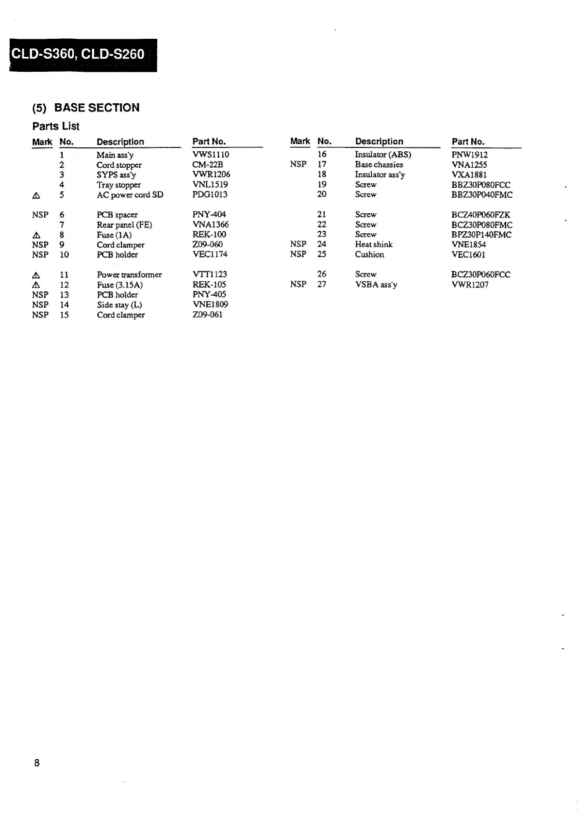
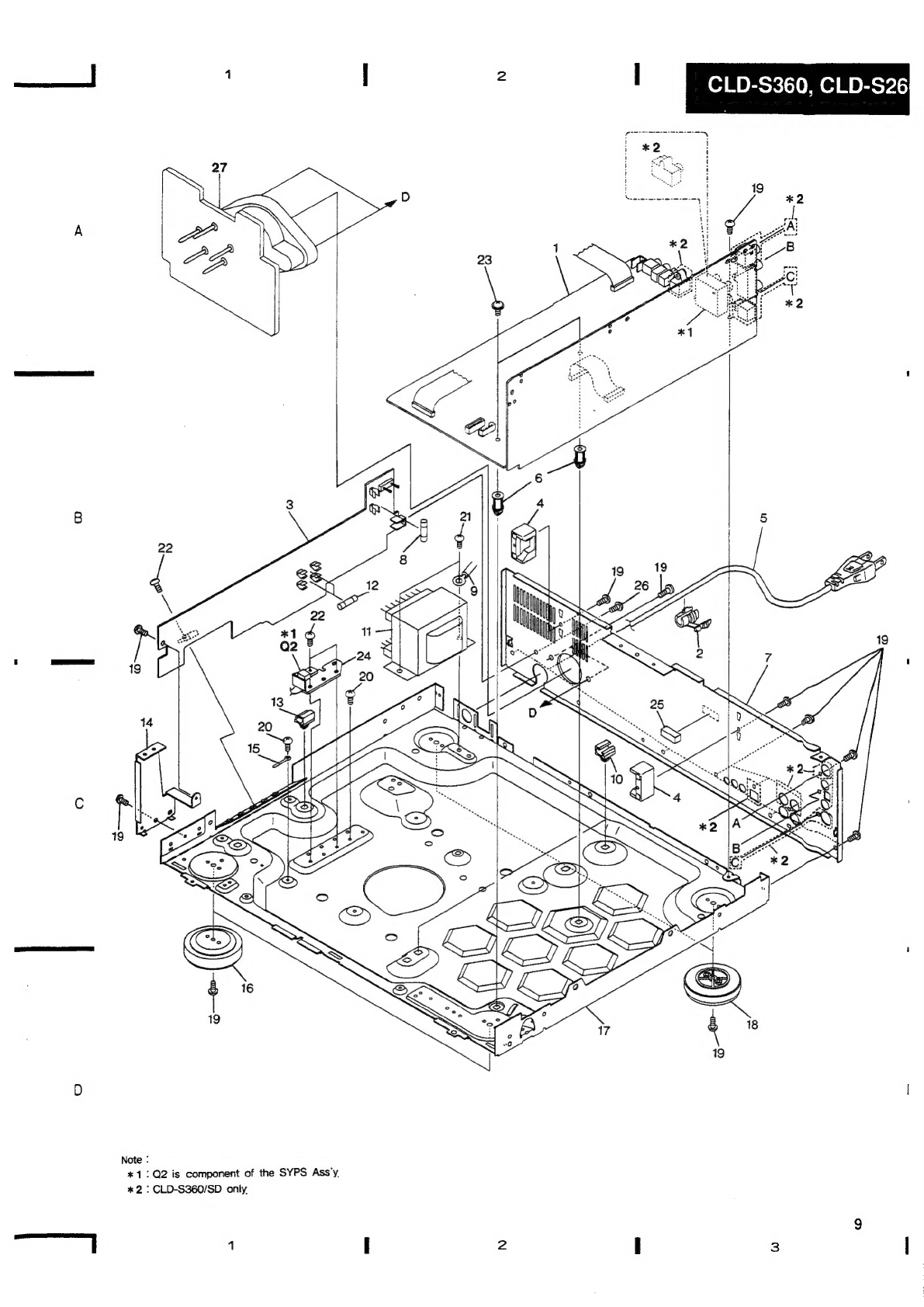
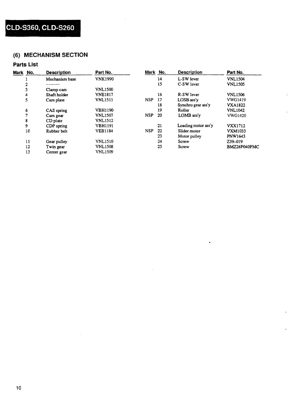
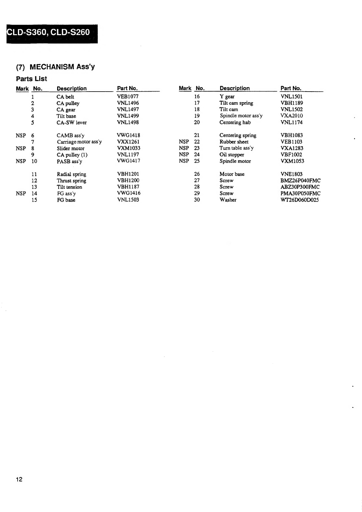
Pioneer CLD-S360 User manual
Other Pioneer CD Player manuals

Pioneer
Pioneer CMX-3000 User manual

Pioneer
Pioneer PD-95 User manual

Pioneer
Pioneer CMX-3000 User manual

Pioneer
Pioneer DEH-P410 User manual

Pioneer
Pioneer PD-30-K User manual

Pioneer
Pioneer LaserDisc CLD-1450 User manual

Pioneer
Pioneer CLD-99 User manual

Pioneer
Pioneer PD-M406 User manual

Pioneer
Pioneer PD-M503 User manual

Pioneer
Pioneer DEH-X8750BT User manual

Pioneer
Pioneer PD-M435 User manual

Pioneer
Pioneer LaserDisc CLD-D760 User manual

Pioneer
Pioneer X-CM32BTD-k/-w User manual

Pioneer
Pioneer CMX-3000 User manual

Pioneer
Pioneer DEH-P5450 User manual

Pioneer
Pioneer PD-F705 User manual

Pioneer
Pioneer CDX-FM1277 User manual

Pioneer
Pioneer CLD-1010 User manual

Pioneer
Pioneer CLD-V300 User manual

Pioneer
Pioneer DEH-P410 User manual