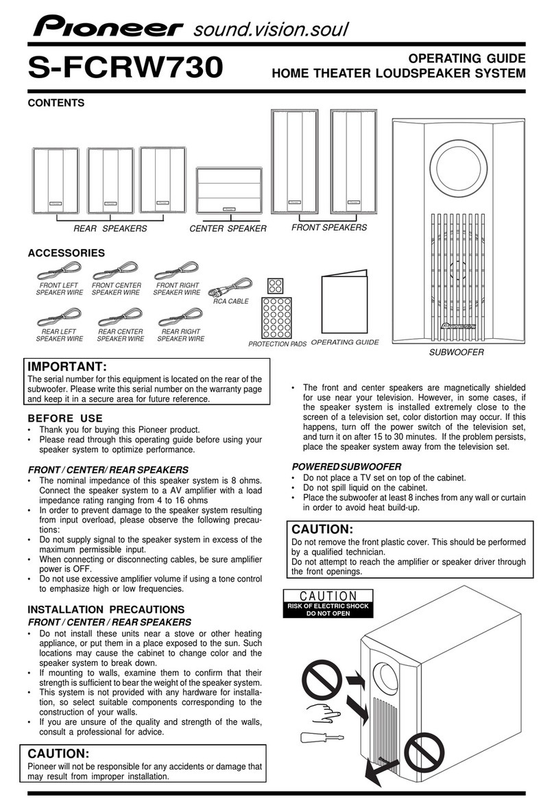
Pioneer HTZ-7 VisionPlus User manual

ORDER NO.
PIONEER ELECTRONIC CORPORATION 4-1, Meguro 1-Chome, Meguro-ku, Tokyo 153-8654, Japan
PIONEER ELECTRONICS SERVICE, INC. P.O. Box 1760, Long Beach, CA 90801-1760, U.S.A.
PIONEER ELECTRONIC (EUROPE) N.V. Haven 1087, Keetberglaan 1, 9120 Melsele, Belgium
PIONEER ELECTRONICS ASIACENTRE PTE. LTD. 253 Alexandra Road, #04-01, Singapore 159936
PIONEER ELECTRONIC CORPORATION 1999
HTZ-7
DVD SURROUND SYSTEM
RRV2076
T–DZY JAN. 1999 Printed in Japan
HTZ-C7
HTZ-SW7
DVD CENTER UNIT
POWERED SUBWOOFER
THIS MANUAL IS APPLICABLE TO THE FOLLOWING MODEL(S) AND TYPE(S).
Type Model
HTZ-7 Power Requirement Remarks
KU/CA AC120V
1. SAFETY INFORMATION .......................................2
2. EXPLODED VIEWS AND PARTS LIST................... 3
3. SCHEMATIC DIAGRAM ...................................... 19
4. PCB CONNECTION DIAGRAM ............................ 54
5. PCB PARTS LIST ................................................ 79
6. ADJUSTMENT .................................................... 90
7. GENERAL INFORMATION .................................. 99
7.1 PARTS .......................................................... 99
7.1.1 IC ............................................................ 99
7.1.2 DISPLAY ............................................... 105
This product is a system(s) component.
This product does not function properly when independent; to avoid malfunctions, be sure
to connect it to the prescribed system component(s), otherwise damage may result.
HTZ-7 is a combination of the following components.
DVD SURROUND SYSTEM (HTZ-7) DVD CENTER UNIT (HTZ-C7)
POWERED SUBWOOFER (HTZ-SW7)
AMP ASSY (A-SW7)
CONTENTS 7.2 DIAGNOSIS................................................. 106
7.2.1 FAIL-SAFE ............................................ 106
7.2.2 SINGLE UNIT OPERATION METHODS.. 107
7.2.3 DISASSEMBLY ..................................... 109
7.2.4 TEST MODE ......................................... 114
7.3 BLOCK DIAGRAM ....................................... 118
7.4 REMOTE CONTROL UNIT ........................... 120
7.4.1 EXPLODED VIEWS AND PARTS LIST ... 120
7.4.2 SCHEMATIC DIAGRAM......................... 122
8. PANEL FACILITIES AND SPECIFICATIONS ...... 123

HTZ-7, HTZ-C7, HTZ-SW7
2
(FOR USA MODEL ONLY)
1. SAFETY INFORMATION
1. SAFETY PRECAUTIONS
The following check should be performed for the
continued protection of the customer and service
technician.
ANY MEASUREMENTS NOT WITHIN THE LIMITS
OUTLINED ABOVE ARE INDICATIVE OF A PO-
TENTIAL SHOCK HAZARD AND MUST BE COR-
RECTED BEFORE RETURNING THE APPLIANCE
TO THE CUSTOMER.
2. PRODUCT SAFETY NOTICE
Many electrical and mechanical parts in the appli-
ance have special safety related characteristics. These
are often not evident from visual inspection nor the
protection afforded by them necessarily can be ob-
tained by using replacement components rated for
voltage, wattage , etc. Replacement parts which have
these special safety characteristics are identified in
this Service Manual.
Electrical components having such features are
identified by marking with a on the schematics and
on the parts list in this Service Manual.
The use of a substitute replacement component which
does not have the same safety characteristics as the
PIONEER recommended replacement one, shown in
the parts list in this Service Manual, may create shock,
fire, or other hazards.
Product Safety is continuously under review and
new instructions are issued from time to time. For
the latest information, always consult the current
PIONEER Service Manual. A subscription to, or ad-
ditional copies of, PIONEER Service Manual may be
obtained at a nominal charge from PIONEER.
LEAKAGE CURRENT CHECK
Measure leakage current to a known earth ground
(water pipe, conduit, etc.) by connecting a leakage
current tester such as Simpson Model 229-2 or
equivalent between the earth ground and all exposed
metal parts of the appliance (input/output terminals,
screwheads, metal overlays, control shaft, etc.). Plug
the AC line cord of the appliance directly into a 120V
AC 60 Hz outlet and turn the AC power switch on. Any
current measured must not exceed 0.5 mA.
Also test with plug
reversed
(Using AC adapter
plug as required)
Device
under
test
Test all exposed
metal surfaces
Earth ground
Leakage
current
tester
Reading should
not be above
0.5 mA
AC Leakage Test
REMARQUE
(POUR MODÈLE CANADIEN SEULEMENT)
Les symboles de fusible (fusible de type rapide) et/ou (fusible
de type lent) sur CCI indiquent que les pièces de remplacement doivent avoir la
même désignation.
NOTICE
(FOR CANADIAN MODEL ONLY)
Fuse symbols (fast operating fuse) and/or (slow operating fuse)
on PCB indicate that replacement parts must be of identical designation.
This service manual is intended for qualified service technicians; it is not meant for the casual
do-it-yourselfer. Qualified technicians have the necessary test equipment and tools, and have been
trained to properly and safely repair complex products such as those covered by this manual.
Improperly performed repairs can adversely affect the safety and reliability of the product and may
void the warranty. If you are not qualified to perform the repair of this product properly and safely, you
should not risk trying to do so and refer the repair to a qualified service technician.
WARNING
This product contains lead in solder and certain electrical parts contain chemicals which are known to the state of California to
cause cancer, birth defects or other reproductive harm.
Health & Safety Code Section 25249.6 – Proposition 65
IMPORTANT
THIS PIONEER APPARATUS CONTAINS
LASER OF CLASS 1.
SERVICING OPERATION OF THE APPARATUS
SHOULD BE DONE BY A SPECIALLY
INSTRUCTED PERSON.
LASER DIODE CHARACTERISTICS
MAXIMUM OUTPUT POWER: 7 mw
WAVELENGTH: 650 nm
HTZ-7, HTZ-C7, HTZ-SW7
3
1
3
17
17
2
15
16
4
5
6
9
12
10
11
19
7
18
Refer to “ 7.4 REMOTE
CONTROL UNIT ”.
2. EXPLODED VIEWS AND PARTS LIST
1 Protector A AHA7242
2 Protector B AHA7257
3 Protector C AHA7244
4 Packing Case AHD7741
5 Packing Sheet (750 ×600 ×0.5) Z23–007
6 Operating Instructions ARB7174
(Setting up the HTZ–7)
(English/French)
7 Operating Instructions ARB7175
(Basic/Detailed) (English/French)
8 ……………………
9 FM Antenna ADH7004
10 AM Loop Antenna ATB7009
11 Remote Control (CU–HT004) AXD7189
NSP 12 Alkaline Batteries (AA/LR6) VEM1012
13 ……………………
14 ……………………
NSP 15 Warranty ARY7023
NSP 16 Polyethylene Bag Z21–010
(100 ×230 ×0.018)
17 Polyethylene Bag Z21–038
(0.03 ×230 ×340)
18 Protector E AHA7258
19 Battery Cover 103RRC14701R
2.1 DVD CENTER UNIT (HTZ-C7)
2.1.1 PACKING
NOTES : Parts marked by “ NSP ” are generally unavailable because they are not in our Master Spare Parts List.
The mark found on some component parts indicates the importance of the safety factor of the part.
Therefore, when replacing, be sure to use parts of identical designation.
Screw adjacent to mark on the product are used for disassembly.
PACKING PARTS LIST
Mark No. Description Part No.

HTZ-7, HTZ-C7, HTZ-SW7
4
CN6201
CN7801
CN5506
CN5503
CN5501
CN5508 CN5504
CN5502
CN5505
CN101
CN105
CN106
CN802
CN102
CN201
CN107
CN803
CN801
20
12
19
3
26 28
26
23
24
22
26
37
26
21
26
26
26 33
26
26
11
11
17
18
2
30
29
27 31
28 26
36
26
25
39 38
13
34
15
16
26 26
7
26
26 32
26
1
25
6
25
8
10
9
14
5
4
A
B
B
A
a
a
b
c
e
d
C
C
D
D
9
26
26
26
26
26
33
35
EXTERIOR (2/2)
EXTERIOR (2/2)
EXTERIOR (2/2)
EXTERIOR (2/2)
Refer to “ 2.1.3 EXTERIOR (2/2) ”.
2.1.2 EXTERIOR (1/2)

HTZ-7, HTZ-C7, HTZ-SW7
5
1 VIDEO ASSY AWU7284
2 MOTHER ASSY AWU7285
3 FRONT (1) ASSY AWU7163
4 FRONT (2) ASSY AWU7164
5 LAMP ASSY AWU7165
6 FM/AM TUNER MODULE AXQ7065
7 Rear Panel ANC7814
8 FCC Holder ANG7231
9 Radiation Sheet VEB1285
10 Heat Sink VNE2134
11 Screw ABA7048
12 Front Skirt AMB7528
NSP 13 Side Panel L AMB7615
NSP 14 Side Panel R AMB7616
15 Side Skirt L AMB7532
16 Side Skirt R AMB7533
17 Front Alumi ANB7136
18 Top Alumi ANB7137
19 Panel Base Assy AXG7069
NSP 20 LED Lens AAK7581
NSP 21 Panel Base AMB7526
22 Illumination Filter VEC1950
23 Illumination Holder VNK4098
24 Illumination Lens VNK4168
25 Screw BBZ30P060FMC
26 Screw BBZ30P100FZK
27 17P FFC/60V ADD7108
(CN5503 += CN7005)
28 7P FFC/60V ADD7115
(CN5901 += CN5505)
29 7P FFC/60V ADD7137
(CN106 += CN5506)
30 14P FFC/60V ADD7138
(CN105 += CN5502)
31 12P FFC/60V ADD7139
(CN301 += CN107,
CN5501 += CN11)
32 Screw (3 ×8) ABA7050
NSP 33 Tape AEB7143
34 Side Panel L Assy AXG7073
35 Side Panel R Assy AXG7074
36 65 Label ARW7050
37 Fuse Caution Label ARW7051
38 Cushion E AEB7140
39 Cushion D AEB7139
EXTERIOR (1/2) PARTS LIST
Mark No. Description Part No.

HTZ-7, HTZ-C7, HTZ-SW7
6
CN7005
CN7004
CN7501
CN101
CN105
CN106
CN802
CN107
CN803
CN11
CN10
CN801
CN7502
CN7002
11
42
42
42
42
51
42
42
42
42
42
6
5
15
16
29
30
31
22
36
15
20
48 12
24
44
47
46
25
37
43
10
43
38
23
45
2
31 50
19 27
26
39
40
3
13 49
31 4
32
33
7
8
41
12
17
1
11
18
21
21
9
12
e
d
f
f
g
c
b
g
h
i
i
h
14
To VIDEO ASSY
CN7801
EXTERIOR (1/2)
EXTERIOR (1/2)
EXTERIOR (1/2)
EXTERIOR
(1/2)
EXTERIOR (1/2) 42
42
35
34
33
34
36
42
42
42
42
42
42
Refer to “ 2.1.4 LOADING
MECHANISM ASSY”.
2.1.3 EXTERIOR (2/2)

HTZ-7, HTZ-C7, HTZ-SW7
7
1 SVIDEO ASSY AWU7283
2 POWER MAIN ASSY AWU7286
3 POWER SUB ASSY AWU7287
4 AC ASSY AWU7288
5 DVDM ASSY VWS1364
6 FLASH ROM (IC6003) VYW1570
7 Power Transformer (T1) ATS7238
8 Fuse (1A/125V, FU1) REK1075
9 Fan Motor AXM1019
NSP 10 Loading Mechanism Assy VWT1147
11 Leg AEB7090
12 Rubber Bush AEB7134
NSP 13 PCB Spacer (3 ×12) AEC1372
NSP 14 Chassis ANA7075
15 PCB Holder (A) ANG7202
16 PCB Holder (B) ANG7206
17 Fan Cover ANG7208
18 Fan Holder ANG7230
19 Shield Case ANK7046
20 Cover ANK7047
21 Screw BBZ30P300FZK
NSP 22 Edging Saddle (S) DEC1761
23 Tray Spring VBH1277
24 Clamper Plate VNE2068
25 Bridge VNE2069
26 Tray VNL1731
27 17P FFC/60V ADD7108
(CN5503 += CN7005)
28 ……………………
29 7P FFC/60V ADD7137
(CN106 += CN5506)
30 14P FFC/60V ADD7138
(CN105 += CN5502)
31 12P FFC/60V ADD7139
(CN301 += CN107,
CN5501 += CN11)
32 7P FFC/60V ADD7109
(CN7801 += CN7501)
33 17P FFC/60V ADD7111
(CN802 += CN7502)
34 14P FFC/60V ADD7112
(CN803 += CN7004)
35 Housing Assy (14P) AKP7033
(CN101 += CN10)
36 4P Connector AKP7046
(CN801 += CN7002)
37 Clamper VNL1738
38 Tray Stopper VNL1739
39 Tray Panel AMB7534
40 DVD Badge VAM1076
41 Tray Label VRW1628
42 Screw BBZ30P060FMC
43 Screw BBZ30P100FZK
44 Screw BPZ26P080FZK
45 Insulation Sheet B AEC7186
46 Insulation Sheet AEC7187
47 Nylon Rivet (3 ×4.5) RBM–003
48 Label ARW7048
49 Cushion F AEB7141
50 Cushion G AEB7142
51 Spacer AEB7151
EXTERIOR (1/2) PARTS LIST
Mark No. Description Part No. Mark No. Description Part No.

HTZ-7, HTZ-C7, HTZ-SW7
8
11
13
12 14
15
16
8
7
17
9
10
18
2
3
4
5
6
1
¶Top View
¶Bottom View
20
Refer to “ 2.1.5 SERVO
MECHANISM ASSY”.
2.1.4 LOADING MECHANISM ASSY
1 Servo Mechanism Assy-S VXX2538
2 Screw DBA1006
3 Drive Cam VNL1736
4 Drive Gear VNL1735
5 Lock Plate VNL1820
6 Loading Base VNL1730
7 Rubber Belt VEB1260
8 Gear Pulley VNL1733
NSP 9 LOSB Assy VWG1885
10 Loading Gear VNL1734
11 Loading Motor Assy VXX2505
12 DC Motor PXM1027
13 Motor Pulley PNW1634
NSP 14 LOMB Assy VWG1886
15 Connector Assy (2P) VKP2198
(LOMB CN401 += LOSB CN303)
16 Screw VBA1055
17 Screw Z39–019
18 Flexible Cable (8P) VDA1649
(LOSB CN302 += INSB CN202)
19 ……………………
20 Stopper DNH2076
LOADING MECHANISM ASSY PARTS LIST
Mark No. Description Part No. Mark No. Description Part No.

HTZ-7, HTZ-C7, HTZ-SW7
9
3
24
5
6
7
29
9
14 30
13
19
18
18
16
26
15
32
8
1
10
18
18
17
27
11
12
9
24
31
23
21
20
25
28
22
¶Top View ¶Bottom View
2.1.5 SERVO MECHANISM ASSY
1 Spindle Motor Assy VXX2563
2 Magnet Holder Assy VXX2507
NSP 3 Magnet VYM1024
NSP 4 Magnet Holder VNE2070
5 Centering Ring VNL1746
6 Centering Spring VBH1278
NSP 7 Disc Table VNL1747
NSP 8 Motor VXM1071
9 Screw JGZ17P028FMC
10 Sub Guide Bar VLL1489
11 Guide Bar VLL1488
12 Mechanism Base VNL1748
13 Hook VNL1770
14 Hook Spring VBH1291
15 Slider VNL1745
16 Hold Spring VNC1011
17 Pickup Assy VWY1046
18 Floating Rubber DEB1315
19 Float Base VNL1732
20 Gear D VNL1766
21 Gear Spring VBH1306
22 Gear E VNL1767
23 Gear F VNL1768
24 Motor VXM1062
NSP 25 INSB Assy VWG1883
26 Screw PBZ20P050FMC
27 Flexible Cable (20P) VDA1680
(DVDM CN102 += Pickup Assy)
28 Connector Assy (3P) VKP2150
(INSB CN201 += FGSB CN101)
29 Table Sheet DEC2040
30 Screw PBA1048
NSP 31 FGSB Assy VWG1884
NSP 32 Sheet VEC1959
SERVO MECHANISM ASSY PARTS LIST
Mark No. Description Part No. Mark No. Description Part No.

HTZ-7, HTZ-C7, HTZ-SW7
10
12
12
11
9
810
13
17
33
1 (1/2)
2 (1/2)
3
4
3
6
7
2(2/2)
1 (2/2)
15
16
14
5
34
30
31
30
32
18
29
28
27
19
22
20
26
21
23
25 24
2.2 POWERED SUBWOOFER (HTZ-SW7)
2.2.1 PACKING

HTZ-7, HTZ-C7, HTZ-SW7
11
1 Protector (L) SHA2138
2 Protector (R) SHA2139
3 Packing Sheet SHC1723
4 Packing Case SHG2197
NSP 5 Cushion Set SEA1528
NSP 6 Polyethylene Bag SHL–051
7 Leg SXK1046
8 Display Cable (L= 3m) ADE7027
9 Digital Audio Cable (L= 3m) ADE7028
10 Control Cable (L= 3m) ADE7031
11 Video Cable (L= 3m) ADE7036
12 AC Power Cord ADG7021
13 Polyethylene Bag Z21–038
(0.03 ×230 ×340)
14 Packing Case (for Accessories) AHD7650
15 Packing Case (for Display Unit) AHD7651
16 Spacer AHD7652
17 Packing Sheet RHC1052
NSP 18 Accessory Kit SEA1534
19 Speaker Cords (5m ×3) SDS1065
NSP 20 Speaker Cords (10m ×2) SDS1066
NSP 21 Screw Package SEA1530
22 Installation Screws BMZ40P120FMC
23 Non Skid Pads SEP1189
NSP 24 Polyethylene Bag S1 SHL1225
25 Cord Labels SRW1066
NSP 26 Polyethylene Bag S2 SHL1223
27 Top Protector SHA2134
28 Bottom Protector SHA2135
29 Packing Case SHG2198
NSP 30 Polyethylene Bag S2 SHL1224
NSP 31 Polyethylene Bag S1 SHL1225
NSP 32 Satellite Speakers HTZ–ST7
NSP 33 Display Unit DU–HT7
34 Caution Card ARB7190
PACKING PARTS LIST
Mark No. Description Part No.

HTZ-7, HTZ-C7, HTZ-SW7
12
22
22
20
22
22
22
22 6
19 1
3
2
20
4
23 23
18
14
21
9
8
10
17 7
15
16
16
11
12
13
25
24
9
Refer to “ 2.2.3 AMP ASSY ”.
2.2.2 EXTERIOR

HTZ-7, HTZ-C7, HTZ-SW7
13
NSP 1 Cabinet SMM1817
2 Grille SMG1623
NSP 3 Amp Assy A–SW7
4 Top Guard AAK7646
5 ……………………
6 Connection Cord SDF1073
7 Packing SEC1423
NSP 8 Packing SEC1429
NSP 9 Damper SEC1430
10 Damper SEC1431
NSP 11 Bush SEP–150
NSP 12 Acoustic Absorbent SMV1942
13 Damper SER1236
NSP 14 Damper Plate SLX1141
NSP 15 Duct SMR1302
NSP 16 Acoustic Absorbent SMV1936
NSP 17 Duct Ring SNK2348
NSP 18 Top Cover SNK2354
19 Speaker Q20EU82–53F
20 Screw (for Top Guard) BBZ30P080FZK
21 Screw (for HP Assy) BPZ30P080FMC
22 Screw (for Speaker, Duct BYC40P200FZB
and Amp Assy)
23 Screw (For Top Cover) SBA1095
24 Duct Assy SXB1370
25 Top Cover Assy SXB1368
EXTERIOR PARTS LIST
Mark No. Description Part No.

HTZ-7, HTZ-C7, HTZ-SW7
14
1
15
14
11
17
17
16
17
19
16
16
16
16
6
16
16
7
19
19
19
19
17
4
3
13
20 13
17
17
10
10
16
16
16
16
16
9
9
18
18
21
17
812
17
5
2
Refer to “ 7EXTERIOR (2/2) ”.
2.2.3 AMP ASSY (A-SW7)
Exterior (1/2)

HTZ-7, HTZ-C7, HTZ-SW7
15
1 POWER SUPPLY ASSY AWU7289
2 SWF ASSY AWU7292
3 IF ASSY AWU7293
4 MAIN ASSY AWU7362
5 Fuse (4A, FU8001) REK1082
6 Screw (3 ×8) ABA7050
7 Rear Panel ANC7809
8 Bottom Panel ANC7706
9 Side Panel ANC7707
10 Bridge ANG7200
11 PCB Holder ANG7203
12 Leg Assy AEC7165
13 PCB Fixing Jig DEC1231
NSP 14 Cord Clamper S DEC1574
NSP 15 PCB Holder PNW2029
16 Screw BBT30P080FZK
17 Screw BBZ30P080FMC
18 Cushion C AEB7138
19 Screw IBZ30P100FCC
20 Cushion D AEB7148
21 65 Label ARW7050
EXTERIOR (1/2) PARTS LIST
Mark No. Description Part No.

HTZ-7, HTZ-C7, HTZ-SW7
16
19
26 26
6
9
26
26
17
30
20
18
26
26
4
21
22
21
2
28
7
28
10
26
11
26
26 24
1
25
25
26
26
26
26
25
27 27 27
16
15
26
15
26
26
15
26
26
12
23
27
27
27
14 13
3
5
26
31
8
To IF ASSY
CN3025
Exterior (2/2)

HTZ-7, HTZ-C7, HTZ-SW7
17
1 AMP ASSY AWU7290
2 PRIMARY ASSY AWU7291
3 HP ASSY AWU7295
4 SECONDARY ASSY AWU7175
5 REG (1) ASSY AWU7176
6 DOLBY DIG 9624 ASSY AWX7271
7 Power Transformer (T8001) ATS7222
8 Cord with Plug ADE7030
9 Jumper Wire D15A10–150–2651
NSP 10 Chassis ANA7074
11 Top Panel ANC7808
12 Fan Holder ANG7199
13 PCB Holder ANG7201
14 IF Holder ANG7204
15 HS Holder ANG7207
NSP 16 Heat Sink ANH7091
17 Shield Case (A) ANK7044
NSP 18 Shield Case (B) Assy AXA7074
NSP 19 Earth Sleeve ALA7010
NSP 20 Shield Case (B) ANK7045
NSP 21 PCB Support AEC1006
22 Insulation Sheet AEC7148
23 Mica Sheet AEE7028
NSP 24 Locking Wire Saddle DEC1305
25 Screw (3 ×16) ABA1056
26 Screw BBZ30P080FMC
27 Screw BBZ30P100FCC
28 Screw BCZ40P060FMC
30 Cushion A AEB7136
31 Cushion B AEB7137
EXTERIOR (2/2) PARTS LIST
Mark No. Description Part No.

HTZ-7, HTZ-C7, HTZ-SW7
18
1
2
3
4
5
6
7
89
9
2
6
6
4
10
13 12
13
3
14
14
1
7
8
15
8
4
11
9
1 Cabinet SNK2305
2 Grille SMG1618
3 Speaker Wire SDD1269
4 Packing (for Grille) SEC1398
5 ……………………
6 Packing (for Grille) SEC1401
7 Packing SEE1066
8 Damper SES1021
9 Input Terminal SKX1056
10 Acoustic Absorben SMV1919
(for Grille rib)
NSP 11 Acoustic Absorbent SMV1940
12 Speaker B70AC45–57F
13 Screw BPZ40P060FMC
14 Screw BPZ40P120FMC
15 Mini Stand SNK2312
2.2.4 SATELLITE SPEAKER (HTZ-ST7)
2.2.5 DISPLAY UNIT (DU-HT7)
1 FLDP ASSY AWU7294
2 CNB ASSY AWU7172
3 Screw (3 ×8) ABA7050
4 Window AAK7582
5 Leg AEB7090
6 FL Filter AEC7150
7 Display Panel AMB7531
8 Rear Cover AMC7030
9 Screw BPZ30P080FMC
SATELLITE SPEAKER PARTS LIST
Mark No. Description Part No.
DISPLAY UNIT PARTS LIST
Mark No. Description Part No.

HTZ-7, HTZ-C7, HTZ-SW7
19
A
B
C
D
1234
1234
A
D
LOMB ASSY
(VWG1886)
B
LOSB ASSY
(VWG1885)
C
INSB ASSY
(VWG1883)
FGSB ASSY
(VWG1884)
SERVO
MECHANISM
ASSY-S
(VXX2538)
LOADING MECHANISM ASSY
LOADING MOTOR
ASSY :VXX2505
CN401
B2B-PH-K-S
CN303
B2B-PH-K-S
CN302
VKN1268 CN301
VKN1272
CN202
VKN1239
CN101
B3B-PH-K-S
CN201
B3B-PH-K-S
PC101
GP2S27(B)
S201
DSG1017
VSK1011
S301
SPINDLE MOTOR
ASSY : VXX2563
SLDR MOTOR
VXM1062
PICKUP ASSY
(VWY1046)
: RF SIGNAL ROUTE
: FOCUS SERVO LOOP LINE
: TRACKING SERVO LOOP LINE
: SLIDER SERVO LOOP LINE
(F)
(T)
(S)
(F)
(F)
(F)
(F)
(F)
(F)
(T)
(T)
(F)
(F)
(T)
(T)
(T)
(T)
(S)
(S)
(S)
(S)
(S)
(S)
ADD7139
DVDM ASSY
(VWS1364)
E
(E1/3 to E3/3)
3. SCHEMATIC DIAGRAM
3.1 DVD CENTER UNIT (HTZ-C7)
DCBA
Note: When ordering service parts, be sure to refer to "EXPLODED VIEWS AND PARTS LIST" or "PCB PARTS LIST".
3.1.1 OVERALL CONNECTION DIAGRAM (1/2), LOMB, LOSB, INSB and
FGSB ASSEMBLIES

HTZ-7, HTZ-C7, HTZ-SW7
20
A
B
C
D
1234
1234
MOTHER ASSY
(AWU7285)
VIDEO ASSY
(AWU7284)
SVIDEO ASSY
(AWU7283)
FM/AM TUNER
MODULE
(AXQ7065)
ADD7138 14P ADD7137 7P
AKP7046 4P
ADD7112 14P
ADD7111 17P
ADD7109
14P
H
(H
1/2,
H
2/2
)
FI
G
DVDM ASSY
(VWS1364)
E
(E
1/3 to
E
3/3
)
3.1.2 OVERALL CONNECTION DIAGRAM (2/2)
Other manuals for HTZ-7 VisionPlus
3
This manual suits for next models
2
Table of contents
Other Pioneer Home Cinema Speakers manuals

Pioneer
Pioneer S-FCRW730 User manual

Pioneer
Pioneer NS-DV990 User manual

Pioneer
Pioneer SP-FS52 Manual

Pioneer
Pioneer S-FCRW240B-S User manual

Pioneer
Pioneer HTZ-7 VisionPlus User manual

Pioneer
Pioneer HTZ111DVD User manual

Pioneer
Pioneer MCS-838 User manual

Pioneer
Pioneer HTZ-55DV User manual

Pioneer
Pioneer HTZ-424DVD User manual

Pioneer
Pioneer HTP-072 User manual