manuals.online logo
Brands
  1. Home
  2. •
  3. Brands
  4. •
  5. Pioneer
  6. •
  7. Stereo Receiver
  8. •
  9. Pioneer SX-2600 User manual

Pioneer SX-2600 User manual

Operating
Instructions
STEREO
RECEIVER
X2600
I/O
*
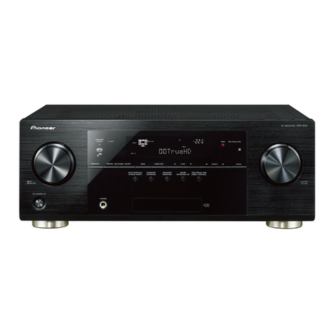
The
illustration
shows
model
SX-2600.
Thank
you
lor
buying
this
Pioneer
product
ase
read
through
these
ape
sso
you
will
know
how
to
operate
your
mode!
properly.
After
you
have
finished
reading
the
instructions,
put
them
away
in
a
sate
place
for
future
reference.
In
sorne
countries
of
regions,
the
shape
of
the
pawer
plug
and
power
outlet
may
sometimes
differ
from
that
shown
in
the
explanatory
drawings.
However,
the
method
of
connecting
and
operating
the
unit
oH
IRS
ET
is
the
same.
WARNING:
to
prevent
FIRE
OR
SHOCK
HAZARD,
DO
NOT
EXPOSE
THIS
APPLIANCE
TO
RAIN
OR
MOISTURE.
IMPORTANT
NOTICE
{For
U.S.
and
Canadian
models}
The
serial
number
for
this
equipment
is
located
on
the
rear
panel.
Please
write
this
serial
number
on
your
enclosed
warranty
card
and
keep
it
in
@
secure
area.
This
is
for
your
security.
BEFORE
OPERATING,
CHECK
THE
POSITION
OF
THESE
SWITCHES
...
CHECKING
ACCESSORY
[7
CONNECTIONS
REAR
PANEL
FACILITIES...
FRONT
PANEL
FACILITIES...
SETTING
THE
UNIT
PRIOR
TO
OPERATION
GRAPHIC
EQUALIZER
CONTROLS
............
EMS
ONO
DW
Ww
CONTENTS
[For
Canadian
model]
CAUTION:
to
prevent
ELECTRIC
SHOCK
DO
NOT
USE
THIS
(POLARIZED)
PLUG WITH
AN
EXTENSION
CORD,
RECEPTACLE
OR
OTHER
OUTLET
UNLESS
THE
BLADES
CAN
BE
FULLY
INSERTED
TO
PREVENT
BLADE
EXPOSURE.
ATTENTION:
pour
prevenir
Les
CHOCS
ELECTRIQUES
NE
PAS
UTILISER
CETTE
FICHE
POLARISEE
AVEC
UN
PROLONGATEUR
UNE
PRISE
DE
COURANT
OU
UNE
AUTRE
SORTIE
DE
COURANT,
SAUF
SI
LES
LAMES
PEUVENT
ETRE
INSEREES
A
FOND
SANS
EN
LAISSER
AUCUNE
PARTIE
A
DECOUVERT.
LISTENING
TO
THE
BROADCAST
co
cdeinsnecscssosntnesssiccainaes
8
DIRECT
ACCESS
TUNING
..
PRESET
TUNING........0...0.
TO
LISTEN
TO
OTHER
MUSIC
SOURCES
TAPE
RECORDING
.....-....
HINTS
FOR
BETTER
RECEPTION
SPECIFICATIONS
....
TROUBLESHOOTING
YQ
PIONEER
The
Art
of
Entertainment
iM
PORTANT
The
lightning
flash
with
arrowhesd,
within
an
equilateral
triangle,
is
intended
to
atert
che
user
to
the
presence
of
uninsulated
"dangerous
voltage’
within
the
product's
enclosure
that
may
be
of
sufficient
magnitude
to
constitute
a
risk
of
electric
shock
to
persons.
CAUTION
RISK
OF
ELECTRIC
SHOCK
GO
NOT
OPEN:
CAUTION:
TO
PREVENT
THE
RISK
OF
ELECTRIC
SHOCK,
DO
NOT
REMOVE
COVER
{OR
BACK},
NO
USER-
SERVICEABLE
PARTS
INSIDE.
REFER
SERVICING
TO
QUALIFIED
SERVICE
PERSONNEL.
The
exclamation
point
within
an
equilateral
triangleis
|
intended
to
alert
the
user
to
the
presence
of
important
operating
and
maintenance
(servicing)
instructions
in
the
literature
accompanying
the
appliance.
REAO
INSTRUCTIONS
—
Ai!
the
safety
and
operating
instructions
should
be
read
before
the
applience
is:
operated.
RETAIN
INSTRUCTIONS
~
The
operating
instructions
should
be
retained
for
future
reference
HEED
WARNING
~
Allwarnings
on
the
apaliance
andin
the
operating
instructions
should
be
adhered
to.
FOLLOW
INSTRUCTIONS
~
Alf
operating
and
use
in-
structions
should
be
followed
WATER
AND
MOISTURE
~
The
appliance
should
oot
be
used
near
water
—
for
example.
near
a
bathtub,
washbowl,
kitchen
sink,
laundry
tub,
in
a
wet
base-
ment,
or
near
a
swiraming
pool,
etc
LOCATION
~
The
appliance
should
be
installed
in
a
stable
focation
WALL
OR
CEILING
MOUNTING
-
The
appliance
shouid
not
be
mounted
to
a
wall
or
ceiling
VENTILATION
~
Tha
appliance
should
be
situated
so
|
thar
its
tocation
or
position
does
not
interfere
with
iS
proper
ventilation.
For
example.
the
appliance
should
notbe
situated
on
a
bed,
sofa,
rug,
oF
similar
surface
that
may
block
the
ventilation
openings;
or,
placed
in
a
built-in
installation,
such
as
a
bookcase
or
cabinet
that
may
impede
the
flaw
of
air
through
the
ventilation
openings.
HEAT
~
The
appliance
should
be
situated
away
from
heat
sources
such
as
radiators,
heat
registers,
stoves,
of
other
appliances
{including
amplifiers}
that
produce
heat.
POWER
SOURCES
~
The
applience
should
be
con:
nected
ta
a
power
supply
only
of
the
type
de
sctibed
in
the
operating
instructions
or
as
marked
on
the
appliance
SAFETY
INSTRUCTIONS
2
POWER
LINES
~
An
outdoor
antenna
snould
be
located
away
from
power
jines
NONUSE
PERIODS
~
The
power
cord
of
the
appliance
should
be
unpiugged
from
the
outlet
when
left
un-
used
for
a
tong
period
of
time.
OBJECT
AND
LIQUID
ENTRY
~
Care
should
be
taken
so
that
objects
do
not
fall
and
liquids
are not
spilled
into
the
enclosure
thraugh
cpenings
DAMAGE
REQUIRING
SERVICE
-
The
appliance
should
be
serviced
by
a
Pioneer
authorzed
service
canter
of
qualified
service
personnet
when
r-suaply
cord
ar
the
piug
has
heen
dam-
ve
fallen,
or
lauid
has
been
spilled
into
the
apnlianes
The
appliance
@
The
appl
or
exhib
@
the
ap
damaged
SERVICING
-
The
user
should
nor
allempt
ta
service
the
appiiance
beyond
that
described
in
the
opera
ting
instructions.
For
all
other
servicing,
contact
the
nearest
Pioneer
authorized
service
center
has
been
exposed
to
rain
does
NOt
appeat
te
a
Marked
change
1
has
Deen
dropped
OUTDOOR
ANTENNA
GROUNDING
-
If
an
outside
an-
tenna
is
connected
to
the
antenna
termina}.
be
sure
the
antenns
system
is
grounded
so as
to
provide
soime
protection
against
voltage
surges
and
built
Up
static
chargas
in
the
U.S.A
section
816
of
she
National
Electrical
Code,
ANSVVNFPA
No,
70-1984,
provides
informa
fion
with
respect
to
proper
grounding
of
ihe
m:
and
supporting
structure,
grounding
of
the
lead-in
ware
19
an
antenna
discharge
unit,
size
of
grounding
conductors,
location
of
anteana
discharge
unit
connection
to
grounding
electrodes,
and
require.
ments
for
the
grounding
2
i
may
cause
‘hi
combination
to
overturn
NEC
NATIONAL
ELECTRIC
CODE
ANTENNA
TEADIN
Rt
POWER-CORD
PROTECTION
Power-supply
cords
should
be
routed
so
that
thay
are
nat
likely
to
be
es
walked
Gi
GF
pitched
Ly
Weis
plowed
tay:
against
them.
Pay
particular
atiention
to
cords
at
plugs.
convenience
seceptincles,
and
the
point
ine
where
they
exit
from
the
appliance
GROUND
|
CLAMP
ANTENNA
i
POLARIZATION
~
If
your
purchased
product
is
pro
en
JE
DISCHARGE
UNIT
vided
with
a
polarized
power
plug,
please
read
the
yy
INEC
SECTION
41>,
<2)
|
following
instructions.
Thrs
product
is
equipped
|
|
with
a
polarized
alternating
current
ime
plug
(a
plug
ELECTRIC
i
having
one
blade
wider
than
the
other}.
This
plug
SERVICE
|
‘a
GROUNDING
CONDUCTORS
will
fit
inte
the
power
outtet
only
one
way.
This
15
a
Le
EQUIPMENT
Fa
ed
(NEC
SECTION
310213
safety
feature.
Hf
you
are
unable
to
insert
the
plug
a
Hy
J
fully
into
the
outlet,
try
reversing
the
plug.
If
the
ae
|
ee
:
:
.
plug
shouid
stilt
(ail
to
fit,
contact
your
electrician
to
LPO
~
GROUND
CLAMPS,
Taplace
your
obsolete
outfet.
Do
not
defeat
the
sein
hae
i
safety
purpose
of
the
polaried
ping.
a
POWER
SERVICE
GROUNDING
i
CLEANING
~
The
appliance
should
be
cleaned
only
RODE
SYSTEM
|
|
with
a
polishing
cloth
or
a
soft
dey
cloth.
Never
FIG,
A
CART
250.
PART
H)
|
5
ciaan
with
furniture
wax,
benzing,
insecticides
oF
|
other
volatile
liquids
since
they
may
carrode
the
|
cabinet
cet
ocean
|
|
MAINTENANCE
OF
EXTERNAL
SURFACES
|
*
Use
a
polishing
cloth
or
dry
cloth
ta
wipe
off
dust
and
dirt.
*
When
the
surfaces
are
very
dirty,
wipe
with
a
soft
cloth
dipped
in
some
neutral
cleanser
diluted
five
or
six
times
with
water,
and
POWER-CORD
CAUTION
Handle
the
power
cord
by
the
plug.
Do
not
pull
out
the
plug
by
tugging
the
cord
and
never
touch
the
power
cord
when
your
hands
are
wet
as
this
could
cause
a
short
circuit
or
alectric
shack.
Do
not
place
the
unit,
8
piece
of
furniture,
etc,.
on
the
pawer
cord,
or
pinch
the
cord.
Never
make
a
knot
in
the
cord
ar
tie
it
with
other
cords.
The
power
cords
should
be
routed
such
that
they
are
not
likely
to
be
stepped
on.
A
damaged
power
cord
can
cause
fire
or
give
you
an
electrical
shock,
Check
the
power
cord
once
in
a
while.
When
you
find
it
damagad,
ask
your
nearast
PIONEER
authorized
service
center
or
your
dealer
for
a
replacement.
2
<ARB1214>
wrung
out
weil,
and
then
wipe
again
with
a
dry
cloth.
Do
not
use
furniture
wax
or
cleaners.
«
Naver
use
thinners,
benzine,
insecticide
sprays
and
other
chemicals
on
or
near
this
unit,
since
these
will
corrode
the
surfaces,
en
|
BEFORE
OPERATING,
CHECK
THE
POSITION
OF
THESE
SWITCHES
(model
SX-1700
only)
LINE
VOLTAGE
SELECTOR
SWITCH
Only
multi-voltage
models
are
provided
with
this
switch.
U.S.,
Canadian,
European,
U.K.,
and
Australian
models
sre
not
provided
with
this
switch.
Main
voitages
in
Saudi
Arabia
are
127
V
and
220
V
only,
Never
use
this
model
with
110
V
setting
in
Saudi
Arabia.
;
The
line
voltage
selector
switch
is
on
the
rear
panel,
Before
your
model
is
shipped
from
the
factory,
this
switch
is
set
to
the
power
requirements
of
the
destination.
Check
that
it
is
set
properly
before
plugging
the
power
cord
into
the
AC
outlet.
If
the
voltaae
is
not
properly
set
or
if
you
move
te
an
area
where
the
voltage
requirements
differ,
adjust
the
selector
switch
as
follows
1.
Use
a
medium-size
screwdriver.
2.
Insert
the
screwdriver
into
the
groove
on
the
voltage
selector,
and
adjust
so
that
the
tip
of
the
groove
points
to
the
voltage
value
of
your
area.
—t
1
2204 240V
(}
mov
120-1270
Medium-size
screwdriver
|
CHECKING
ACCESSORY
ITEMS
fi
pe
AM
Loop
Antenna
FM
T-type
Antenna
CHANNEL
STEP
SWITCH
(Multi-voltage
model
only)
(Not
available
on
U.S.
and
Canadian
models)
The
unit
has
been
factory
preset
to
the
channol
allocation
and
de-emnphasis.value
for
the
aroa
in
which
it
is
to
be
sold.
If
these
values
are
set
incorrectly,
the
frequency
display
may
stop
at
the
wrong
frequency,
or
sound
may
be
distorted,
resulting
in
an
inability
to
reproduce
reception
signais
at
their
proper
sound
quality.
For
this
reason,
be
sure
to
confirm
that
the
values
are
set
correctly
before
first
using
the
unit
[100kH2z/1
OkHz}position:
Set
to
this
position
for
areas
with
an
FM
reception
step
of
100kHz,
AM
VOkKHz.
[50kHz/9kHz]position:
Set
to
this
position
for
areas
with
an
FM
reception
step
of
50kHz,
AM
QkHz.
NOTE:
When
unsure
about
the
channel
allocation
and
de-emphasis
values
for
your
area,
consult
your
dealer
for
correct
information.
CHANNEL
STEP
SOkHz-FM-100kHz
SkHz—
AM=—
10kHz
eee
amma!
North
and
South
America
Other
countries
3
<ARB1214>
CONNECTIONS
FM
T-type
antenna
-
AM
toop
antenna
AM
LOOP
ANTENNA
*
Set the
antenna
on
a
level
surface,
and
point
in
the
direction
that
gives
optimum
reception.
*
Do
not
install
the
antenna
in
locations
where
it
touches
the
cover
of
the
receiver
or
other
metal
objects,
or
near
a
CD
player.
personal
computer,
or
television
set.
Ground
Gr
a
‘wb
‘
2
Speaker
system
B
as}
vcr
Turntable
CD
player
Antenna
ground
Although
grounding
is
not
necessary
for
reception
it
is
recommended
for
protection
against
damage
from
lightning
if
an
outdoor
FM
antenna
is
used.
Grounding
is
recommended
as
well,
to
help
reduce
noise
and
hum.
NOTE:
Never
make
the
ground
connection
to
a
gas
pipe
as
sparks
could
cause
the
gas
to
ignite.
Connecting
the
speaker
cords
Cutter
“
a
Speaker
cord
i
10
mm
Twist
the
strands.
ls
Push
up,
Push
down.
@
Insert.
4
<ARBI214>
Cassette
deck
Cassette
deck
Connecting
the
input/output
cords
When
another
stereo
component
(purchased
separately
is
connected,
note
the
following
instructions.
*
Connect
the
plugs
properly.
Faulty
connections
can
cause
noise
and
also
breakdowns
and
failures.
*
The
white
terminal
is
for
left
channel
and
the
red
terminal
is
for
the
right
channel.
NOTE
ABOUT
SPEAKER
CONNECTIONS
*
Speaker
systems
used
should
have
an
impedance
of
between
SO
and
162,
«
Re
sure
that
connections
are
secure
Check
to
make
sure
that
wires
do
not
protrude
from
their
terminals.
*
Do
not
allow
the
speaker
cords
to
become
shorted.
Damage
may
result
fo
your
unit,
*
Do
not
attempt
to
simultaneously
connect
two
sets
of
speakers
to
a
single
side
(A
or
B).
When
using
two
sets
of
speakers,
connect
one
set
to
side
A
and
one
set
to
side
B.
REAR
PANEL
FACILITIES
Go
®
2
CHANNEL
STEP
switch
{See
page
3)
2
FM/AM
ANTENNA
terminals
Use
these
antenna
terminals
for
receiving
FM
and
AM
broadcasts
SINPUT
jacks
PHONO
.
Connect
to
the
output
cables
from
a
turntable
CDay
Connect
to
the
output
jacks
of
a
compact
disc
player
VCR/LINE...Connect
to
the
output
jacks
of
a
video
cassette
recorder,
etc.
2-TAPE
1/DAT
jacks
Connect
these
jacks
to
the
cassette
deck
or
digital
audio
tape
deck.
®
TAPE2
jacks
Connect
these
jacks
to
the
cassette
deck.
‘©
AC
OUTLET
(UNSWITCHED
100
W
MAX)
Power
flows
continually
to
this
outlet,
regardiess
of
whether
the
receiver’s
POWER
switch
is
ON
or
OFF.
Electrical
power
consumption
of
the
connected
equipment
should
not
exceed
100
W.
The
equipment
should
be
disconnected
by
removing
the
mains
plug
from
the
wail
socket
when
not
in
reguiar
use,
e.g.
when
on
vacation.
NOTE:
Do
net
connect
appliances
with
high
power
consumption
such
2s
heaters,
irons,
or
television
sets
to
the
AC
OUTLET,
in
arder
to
avoid
overheating
or
fire
This
can
cause
the
receiver
to
maffunction.
@)
Power
cord
5
VOLTAGE
SELECTOR
{See
page
3)
(9°
SPEAKERS
terminals
A:
Connect
to
a
first
set
of
speakers
B:
Connect
to
a
second
set
of
speakers.
NOTE:
No
sound
will
be
heard
through
the
speakers
when
both
A
and
B
Switches
are
depressed
if
only
one
set
of
speakers
has
been
connected
to
either
A
or
B
SPEAKERS
terminals.
GND
terminal
Cannect
to
the
ground
lead
of
a
turntable.
CONNECTING
THE
POWER
CORD
(For
U.S.A.
and
Canadian
models)
Household
electrical
outlets
are
provided
with
specific
polarity,
a
live
side
and
a
neutral
(ground)
side.
This
unit
utilizes
such
polarity
in
order
to
improve
sound
quality.
As
shown
in
the
illustration,
be
sure
to
insert
the
power
plug
so
that
its
blades
match
the
width
of
slots
in
the
outlet.
Household
electrical
outlet.
Long
slot
is
neutral
{ground}
side.
Insert
the
wide
blade
into
the
ground
side
slot.
5
<ARB1I214>
FRONT
PANEL
FACILITIES
The
illustration
shows
model
SX-2600.
@
PIONES):
@
POWER
switch
When
this
switch
is
pressed,
power
is
supplied
to
the
unit.
Prass
the
switch
again
to
turn
power
OFF.
{Timer
ON/OFF
possible}
When
the
unit
is
switched
ON,
ON/OFF
contro!
can
be
performed
by
means
of
the
optional
timer.
NOTE:
When
the
power
is
initially
turned
ON,
muting
vill
be
applied
to
pravent
sound
from
being
output
for
about
5
seconds.
2)
SPEAKERS
switches
(
MOFF,
=
ON)
ugh
which
you
to
hsten
These
are
used
to
select
the
sy
A:
When
the
speakers
connected
to
A
terminals
are
in
B:
When
the
speakers
connected
to
B
terminais
are
in
use.
*
Turn both
A
and
B
speakers
to
OFF
position
when
only
the
HEADPHONES
are
in
use.
NOTE:
No
sound
wilf
be
heard
through
the
speakers
when
both
A
and
B
Switches
are
depressed
if
only
one
set
of
speakers
has
been
connected
to
either
A
or
8
SPEAKERS
terminals.
@
PHONES
jack
Connect
the
plug
on
your
headphones
to
this
jack.
To
listen
to
a
program
through
the
headphones,
set
both
SPEAKERS
A
and
8
switches
to
the
OFF
position.
@
BAND
Selector
switches
These
switches
are
usud
to
seluct
euher
AM
or
EM
reception.
AM:
Push
this
switch
for
AM
reception.
FM:
Push
this
switch
for
FM
reception.
@
STATION
CALL
switches
These
switches
are
used
to
preset
and
recall
desired
broadcasting
stations.
MEMORY
switch
When
the
unit
is
in
the
frequency
display
mode,
pressing
this
switch
will
result
in
the
memorization
of
the
current
broadcast
band,
reception
frequency,
and
FM
AUTO/MONO
modu.
This
switch
is
also
used
to
input
custom
mamory
names
(see
page
11),
6
<ARBI214>
TAPE
2
MONITOR
switch
Press
when
listening
to
tape
piayback
with
the
cassette
deck
2.
>
SCAN
switch
Use
this
switch
for
both
station
memory
scan
and
custom
memory
scan
operation,
‘3)
Function
switches
Use
to
select
playback
source.
(TAPE
1
/DAT]
—
Press
when
listening
to
tape
playback
with
the
cassette
deck
1
or
digital
audio
tape
deck.
IVCR/LINE]
Fi
en
ister
cennected
to
the
VCR/LINE
terminals.
{CD]
—
Press
when
listening
to
compact
disc
playback
with
a
CD
player.
[TUNER]
—
Press
when
listening
to
AM
or
FM
broadcasts
with
a
tuner.
[PHONO]
~
Press
when
fistening
to
record
playback
on
a
turntable
progi
fom
Gg
CoMpEneNnt
(3d)
FM
MODE
AUTO/MONO
selector
switch
Use
to
select
the
auto
stereo
mode
or
monaural
mode
when
listening
to
FM
broadcasts.
The
monaural
mode
has
been
selected
when
the
FM
MONO
indicator
is
lighted.
Auto
stereo
mode:
Normaily
leave
in
this
mode
for
reception,
When
a
stereo
FM
broadcast
is
received,
it
will
be
automatically
reproduced
in
sterea
sound.
Monaural
mode:
When
receiving
distant
stations
or
stations
with
weak
broadcast
signals,
the
input
signal
may
be
weak,
thus
resulting
in
increased
noise
during
PM
storce
Groddecsts,
tn
this
evant,
sefting
fhe
recervar
fo
the
monaural
mode
will
reduce
the
noise.
in
this
case,
however,
FM
stereo
broadcasts
will
be
reproduced
in
monaural
sound,
NOTE:
This
switch
has
no
effect
on
reception
of
AM
broadcasts.
UD
BALANCE
control
Should
normally
be
left
in
the
center
position,
Adjust
balance
if
the
sound
is
louder
from
one
of
the
speakers.
H
the
right
side
is
louder,
turn
toward
the
L
pasition
and
if
the
left
side
is
fouder,
turn
taward
the
R
pasition
UU
VOLUME
control
Use
to
adjust
volume
level
FRONT
PANEL
FACILITIES
—_—_—_—
inn
@
FM
TUNING
AUTO/MANUAL
switch
Works
during
FM
reception.
Use
this
switch
to
select
either
the
AUTO
mode
or
the
MANUAL
mode.
When
the
“AUTO"
indicator
is
lit,
the
receiver
is
in
the
AUTO
mode
{see
page
8),
@@
DIRECT
ACCESS
tuning
switch
When
this
switch
is
pressed,
the
STATION
CALL
switches
function
as
ten-key
number
switches
for
direct
input
of
the
desired
reception
frequency.
Press
again
to
cancel
this
mode.
!f
the
input
station
falis
outside
of
the
receiver's
tuning
range,
the
display
section
will
display
a
message:
‘‘UPPER"’
if
the
frequency
is
toa
high
and
“LOWER”
if
it
is
too
low
(see
page
9).
@&:
GRAPHIC
EQUALIZER
controls
The
equalizer
is
divided
into
five
frequency
ranges
{100
Hz,
330
Hz,
1
kHz,
3.3
kHz,
10
kHz}
to
tailor
music
to
the
individual
taste
of
the
listener
dé
CUSTOM
MEMORY
switches
Stations
can
be
assigned
to
STATION
CALL
switches
according
to
the
genre
of
material
broadcast
(ROCK,
POP,
OTHER).
You
can
recall
a
particular
genre,
and
scan
all
the
stations
of
that
genre
with
Memory
Scan
unit
you
reach
the
desired
one
@)
OPERATION
DISPLAY
pane!
{a)
Indicates
the
function
or
frequency
by
the
function
switches,
{b}
TUNED
indicator
{c)
FM
STEREO
indicator
id)
FM
MONO
indicator
(e)
TUNING
AUTO/MANUAL
indicator
{f}
DIRECT
ACCESS
tuning
indicator
{g)
SIMULATED
STEREO
indicator
(SX-2600
only)
(th)
CUSTOM
MEMORY
indicator
fi)
Indicates
channel
or
STATION
CALL
number,
{j)
SCAN
indicator
(k)
MEMORY
indicator
{i}
TAPE
2
monitor
indicator
{a}
|
‘amin
WA
WA
WAL
ig)
kA
sane
2]
emi
aM
TAAL
UN
te
828"
{b)
—{3URZ57]
|
OURECTS.
costar]
BATION
access/]|
memory
!
ce
[om
(c)
(stesed’]
Stor
BIMULATED
id}
px
mono
|
imanuaL
BYERES
rit
:
ch
|
i
fg)
(h}
u
(igs)
TUNING
switches
(DOWN,
UP)
UP:
The
FM
or
AM
band
is
scanned
in
the
direction
of
increasing
frequency.
DOWN:
The
opposite
operation
to
that
of
the
UP
switch
takes
place.
43)
SIMULATED
STEREO
switch
(SX-2600
only)
This
turns
monaural
signals
into
simulated
stereo
sound.
Use
this
when
you
wish
to
experience
the
sense
of
stereo
presence
with
AM
broadcasts,
VCR
or
other
monaural
signal
sources.
NOTE:
This
function
can
be
used’
with
stereo
sources,
but
it
will
result
in
a
different
sound
from
the
normal
stereo
sound.
SETTING
THE
UNIT
PRIOR
TO
OPERATION
*
Before
operating
the
unit,
be
sure
to
set
it
as
shown
below.
Set
the
VOLUME
control
to
the
‘’0”’
position.
Press
the
SPEAKERS
switch
TE
corresponding
to
the
speaker
system
to
be
used.
to
the
center
position.
Set
the
TAPE
2
MONITOR
switch
to
OFF
{TAPE
2
indicator
goes
off).
7
<ARBI214>
GRAPHIC
EQUALIZER
CONTROLS
3.3
kHz:
The
3.3
kHz
controi
will
add
brilliance
and
clarity
to
brass
instruments
and
violins.
10
kHz:
The
10
kHz
control
can
be
used
to
make
up
for
missing
high
frequencies
absorbed
by
the
environment
and
to
add
a
natural
crispness
to
music.
The
advantage
of
the
GRAPHIC
EQUALIZER
over
conventional
tone
controls
is
that
with
the
five
controls
of
the
GRAPHIC
EQUALIZER
it
is
possible
to
control
five
different
narrow,
distinct
sections
of
the
audio
band.
With
conventional
tone
controls
a
setting
for
a
bass
or
treble
boost
or
cut
will
aiso
affect
the
lower
or
upper
mid
frequencies.
The
frequency
bands
controlled
by
the
five
slide
controls
have been
chosen
to
yield
the
maximum
possible
control
action
within
the
audio
spectrum.
Emphasize
.
»
frequency
range.
100
Hz:
The
100
Hz
control
is
very
useful
in
enhancing
‘ow
bass
notes
as
in
organ
music.
330
Hz:
The
330
Hz
control
will
allow
you
to
vary
the
upper
bass
frequencies.
The
1
kHz
control
is
the
presence
controi
and
can
be
used
very
effectively
to
emphasize,
or
deemphasize
vocalists.
+
De-emphasize
frequency
range.
1
kHz:
LISTENING
TO
THE
BROADCAST
*
Check
that
all
terminals
are
properly
connected
before
switching
on
MANUAL
TUNING
(FM/AM
reception)
the
unit.
*
Be
sure
to
turn
the
TAPE
2
MONITOR
switch
OFF
when
listening
to
AM
or
FM
broadcasts.
AUTO
TUNING
(FM
reception)
The
electronic
tuning
circuit
inside
the
unit
will
search
for
the
station.
3
5
1.
Turn
on
the
POWER
switch
of
the
unit.
2.
Press
the
TUNER
switch
of
the
function
switches.
2
4
3.
Select
your
desired
broadcasting
band
using
the
BAND
selector
switches.
4.
Prass
the
FM
TUNING
AUTO/MANUAL
switch
to
establish
the
MANUAL
tuning
mode
(the
AUTO
indicator
goes
off}
during
FM
reception.
Use
the
TUNING
switches
to
locate
the
frequency
of
the
desired
station.
For
step-by-step
searching,
press
the
TUNING
switch
once
and
release
it
immediately.
For
continuous
rapid
scanning
keep
the
TUNING
switch
pressed.
The
TUNED
indicator
will
ight
up
when
the
station
is
tuned
in
best.
3.5
.
Turn
on
the
POWER
switch
of
the
unit.
.
Press
the
TUNER
switch
of
the
function
switches.
.
Set
the
BAND
selector
switches
for
FM
reception.
.
Press
the
FM
TUNING
AUTO/MANUAL
switch
to
establish
the
AUTO
tuning
mode
(the
AUTO
indicator
lights).
5.
Press
the
TUNING
switches
“UP
+
”
or
“DOWN
~”
for
a
higher
or
lower
frequency
as
desired.
PWN
—
Fy
The
frequency
will
change
rapidly
during
scanning.
The
AUTO
TUNING
will
stop
automatically
when
the
station
is
located
and
the
TUNED
indicator
will
light
up.
NOTE:
When
the
AUTO
TUNING
is
if
use,
reception
tay
not
be
possible
over
long
distances
or
when
signals
are
weak,
At
these
times
manual
nuning
#8
recommended.
6.
Adjust
the
volume
with
the
VOLUME
control
and
the
tone
with
the
GRAPHIC
EQUALIZER
controls.
8
<ARBI1214
>
NOTE:
The
TUNED
indicator
will
not
function
for
broadcasts
received
over
long
distances
or
when
signals
are
weak,
6.
Adjust
the
volume
with
the
VOLUME
control
and
the
tone
with
the
GRAPHIC
EQUALIZER
controls.
DIRECT
ACCESS
TUNING
LISTENING
TO
BROADCASTS
USING
DIRECT
ACCESS
TUNING
When
you
know
the
frequency
of
the
desired
station,
the
frequency
can
be
input
directly
using
the
STATION
CALL
(number)
switches
in
the
following
way:
1.
Press
the
POWER
switch
to
the
ON
position.
NOTE:
Se
sure
to
turn
ihe
TAPE
2
MONITOR
switch
OFF
when
astemng
to
Al
or
FM
broadcasts.
2.
Seiect
either
FM
or
AM
using
the
BAND
selector
switch.
3.
Press
the
DIRECT
ACCESS
tuning
switch.
*
In
the
Direct
Access
tuning
mode,
the
DIRECT
ACCESS
tuning
indicator
will
light
up.
4.
Input
the
desired
station
frequency
using
the
STATION
CALL
switches.
Example
1:
To
receive
FM
106.00
MHz
DIRECT
ACCESS
tuning
indicator
lights
up
Paty
|
.
a
—
te
¥
Press
the
DIRECT
ACCESS
tuning
i
switch.
|
Po
i
em
|
Mir
;
Press
the
switch
*1.
ees
i
ron
|
Press
the
switch
*0.
-,
|
Press
the
switch
*6,
3
g
co
co
a
ca
2
-
Press
the
switch
*O.
Once
the
station
frequency
has
been
input,
the
receiver
tunes
in
that
frequency.
If
the
input
frequency
fails
below
the
lower
or
higher
limit
of
the
receiver's
receivable
frequency
range
(FM:
87.5
MHz
—
108
MHz;
AM:
530
kHz
—
1,700
kHz
{10
kHz
step),
531
kHz
~
1,602
kHz
(9
KHz
step})
“LOWER”
or
“UPPER”
is
displayed,
indicating
that
the
frequency
which
has
been
input
cannot
be
tuned
in
5.
Adjust
the
sound
volume
and
tone
as
desired.
To
cancel
frequency
input
Direct
access
is
canceled
when
the
DIRECT
ACCESS
tuning
switch
is
pressed
again
Under
the
following
conditions
direct
access
is
canceled
and
the
unit
returns
to
the
condition
in
effect
before
direct
access
was
selected:
(7)
ff
there
is
no
key
input
for
about
five
seconds
after
the
DIRECT
ACCESS
tuning
switch
was
pressed.
‘2)1f
more
than
about
eight
seconds
elapse
between
number
input.
Notes
regarding
direct
access
tuning
(100
kHz
step
only)
There
is
no
need
to
input
the
last
digit
“‘O’’
of
the
desired
station
frequency.
8
<ARBI214>
PRESET
TUNING
FREQUENCY
PRESETTING
Allows
three
stations
per
STATION
CALL
switch
{press
once,
twice,
or
three
times
to
select).
1
2
4
LISTENING
TO
BROADCASTS
USING
PRESET
TUNING
1.
Press
the
POWER
switch
to
the
ON
position.
NOTE:
8e
sure
to
turn
the
TAPE
2
MONITOR
switch
OFF
when
listening
to
AM
or
FIM
broadcasts.
2.
Set
the
BAND
selector
to
either
FM
or
AM.
3.
Tune
in
the
desired
station.
*
See
the
section
“DIRECT
ACCESS
TUNING”
for
information
on
reception
using
the
Direct
Access
Tuning
mode.
*
See
the
section
“AUTO
TUNING”
for
information
on
reception
using
the
Auto
Tuning
mode.
*
See
the
section
“MANUAL
TUNING”
for
information
on
reception
using
the
Manual
Tuning
mode.
In
addition
to
station
frequencies,
the
FM
MODE
(AUTO/MONO}
can
also
be
preset.
4.
Press
the
MEMORY
switch.
5.
Press
the
STATION
CALL
switch
into
which
you
wish
to
preset
the
station.
*
Press
the
STATION
CALL
switch
while
the
MEMORY
indicator
is
flashing
(about
5
seconds).
«
Use
the
STATION
CALL
switches
(*1
—
“9,
*O}
to
select
a
preset
channel.
One
press
seiects
the
1
—
10
range,
two
presses
11
-
20,
and
three
presses
21
30.
[Example]
If
you
press
key
{*3]
8
Once
—
STATION
3
Twice
—
STATION
13
Three
times
—
STATION
23
Press
a
STATION
CALL
switch
within
two
seconds.
When
the
display
stops
flashing,
the
station
is
preset.
NOTE:
Ou
Hut
press
swiches
distiiy
display
vx
Heasd
uty.
6.
Repeat
steps
2
to
5
to
preset
additional
stations.
Total
of
30
AM
and
FM
stations
may
be
preset.
When
you
store
a
new
preset,
it
takes
the
place
of
the
previously
stored
station
(if
any}.
10
<ARB1214>
1.
Press
the
POWER
switch
to
the
ON
position.
2.
Press
the
STATION.
CALL
switch
into
which
the
desired
station
has
been
preset.
*
When
the
Function
switch
is
set
to
a
function
other
than
TUNER,
it
will
switch
to
the
TUNER
function
automatically
if
one
of
the
STATION
CALL
switches
is
pressed.
Tuning
can
be
performed
simply
and
accurately
fallowing
the
above
procedure.
3.
Adjust
the
volume
and
tone
as
desired.
NOTE:
The
contents
of
the
STATION
CALL
switch
will
be
preserved
for
several
days,
even
if
the
receiver
power
cord
is
unplugged.
if
a
preset
station
has
been
erased,
preset
it
again.
Last
station
memory
The
last
received
AM
and
FM
stations
remain
stored
despite
FUNCTION
and/or
POWER
switching.
To
recall,
use
BAND
selector
switches.
HOW
TO
USE THE
CUSTOM
MEMORY
Preset
stations
can
be
classified
into
as
many
as
three
different
genres
according
to
the
material
played
by
the
station.
Each
of
these
three
genres
can
be
given
a
name,
and
Memory
Scan
of
ail
the
stations
of
a
particular
genre
can
be
carried
our.
The
initial
STATION
CALL
numbers
are
classified
and
named
as
follows.
STATION
CALL
NO
|
NAME
1-10
|
POP
11
~
20
|
ROCK
21-30
0
|
OTHER
ILis
recommended
that
you
assign
station
call
switches
to
appropriate
stations
to
be
preset,
Memory
Scan
of
stations
with
the
same
genre
name
Memory
Scan
of
all
stations
classified
under
the
same
genre
name
is
pessibie.
1.
Press
the
CUSTOM
MEMORY
switch
to
display
the
NAME
you
want
to
Memory
Scan.
con
CUR
YOORA
MEMORY
—
a
Eon
paras
cs
—_——
eee
/
|
4
2.
Press
the
SCAN
switch.
=|
ne
*
Memory
Scan
of
stations
classified
under
the
name
displayed
will
be
carried
out
«
Press
the
SCAN
switch
again
to
stop
Memary
Scan
Memory
Scan
of
all
the
station
caii
numbers
You
can
recall
all
of
the
station
cail
numbers
by
pressing
the
SCAN
switch
while
the
display
shows
the
frequency
indication.
ew!
(
Press
the
SCAN
switch
again
to
stop
Memory
Scan.
PRESET
TUNING
Reclassification
of
a
station
under
a
different
genre
name
{i
is
possible
to
change
the
genre
classificution
of
5
station.
{Example]
When
you
want
to
change
the
classification
of
the
station
assigned
to
STATION
CALL
number
9
from
“POP
to
“OTHER,”
1.
Press
the
STATION
CALL
9
switch.
oer
Cl
|
EF
re
LT
ame
ae
*
The
station
assigned
to
STATION
CALL
number
9
will
be
recatied.
2.
Press
the
MEMORY
switch.
|
seme
i
Bt
dB
ate
a
|
rm
H
yf
Gy
ii
Pm
oe
arse
zich
*
The
MEMORY
indicator
will
flash.
3.
Press
the
OTHER
switch.
«The
“OTHER
wall
flashy
«
When
the
display
stops
flashing,
the
classification
name
of
STATION
CALL
number
9
change
to
“OTHER.”
NOTE.
Do
not
press
switches
during
display
is
fiashing.
How
to
cancel
CUSTOM
MEMORY
1.
Press
the
STATION
CALL
number
that
you
wish
to
cancel.
2.
Press
the
MEMORY
switch.
*
The
MEMORY
indicator
will
flash.
3.
While
the
MEMORY
indicator
is
flashing,
press
twice
on
one
of
the
three
CUSTOM
MEMORY
switches.
«
The
display
will
show
‘TUNER’.
This
completes
cancellation.
NOTE.
Do
not
press
switches
while
the
display
is
Hashing.
om
<ARBI24>
TO
LISTEN
TO
OTHER
MUSIC
SOURCES
TAPE
RECORDING
[For
a
cassette
deck]
1.
Turn
on
the
POWER
switch
of
the
unit.
Also
turn
on
the
power
to
the
stereo
components
you
wish
to
use.
2.
Use
the
function
switches
and
tape
monitor
switches
as
appropriate
to
select
the
desired
program
source.
|
Function
TAPE
2
j
switch
MONITOR
switch
;
To
listen
to
a
tape
on
the
|
j
cassette
deck
connected
to
-
ON
TAPE
2
jacks
To
listen
to
the
component
t
F
connected
to
VCR/LINE
jacks
MGRILING
OF
To
listen
to
a
CD
cD
!
OFF
To
listen
to
records
PHONO
OFF
4
|
Tolisten
to
TAPE
DAT
|
TAPE
T/DAT
|
OFF
3.
Operate
the
appropriate
stereo
component
to
play
back
the
program
source.
4.
Adjust
the
volume
with
the
VOLUME
control
and
the
tone
with
the
GRAPHIC
EQUALIZER
controls.
12
<ARBI214>
You
can
record
an
FM
or
AM
broadcast,
or
a
sound
source
connected
to
the
VCR/LINE,
CD,
PHONO
terminals.
1.
Turn
on
the
POWER
switch
of
the
unit.
2.
Select
the
sound
source
to
be
recorded.
3.
Turn
on
(or
start)
the
sound
source
to
be
recorded.
4.
Operate
the
cassette
deck
connected
to
the
TAPE
1/
DAT
or
TAPE
2
terminals.
¢
For
details
of
operating
the
cassette
deck,
read
the
operating
instructions
of
the
cassette
deck,
TAPE
RECORDING
COPYING
TAPES
When
two
cassette
decks
are
used,
the
sound
played
back
on
the
deck
*
To
make
a
tupe
copy
with
contents
identical
to
the
original
tape.
connected
to
the
TAPE
7
/DAT
jacks
can
be
recorded
on
the
deck
*
To
edit
8
recording
of
an
FM
broadcast
in
order
to
cut
out
unwanted
connected
to
the
TAPE
2
jacks.
commercials,
recarding
only
the
desired
material
onto
another
tape.
TAPE
V/DAT
TAPE
2
RECORDING
{When
using
two
cassette
decks]
1.
Load
the
playback
tape
{i.e.
the
pre-recorded
tape)
in
3.
Operate
the
cassette
decks
to
begin
copying.
the
deck
connected
to
the
TAPE
1/DAT
jacks,
and
the
Set the
cassette
deck
with
the
original
tape
to
the
playback
mode,
tape
to
be
recorded
in
the
other
deck
connected
to
the
and
set
the
cassette
deck
with
the
non-recorded
tape
to
the
TAPE
2
jacks.
recording
mode.
2.
Press
the
TAPE
1/DAT.
13
<ARBI214>
HINTS
FOR
BETTER
RECEPTION
EXTERNAL
FM
ANTENNA
[Connecting
the
coaxial
cable]
The
main
advantage
of
FM
over
AM
is
the
quality
of
the
broadcast
signal.
in
order
to
benefit
fully
from
the
high
signai
quality
of
FM
broadcasts,
it
is
recommended
that
a
special-purpose
FM
antenna
be
installed.
In
weak
signal
areas,
a
muiti-element
(3
elernent,
5
element,
7
element,
etc.)
antenna
should
be
used.
FM
OUTDOOR
ANTENNA
CONNECTIONS
There
are
two
ways
of
connecting
the
FM
antenna
to
the
antenna
input
terminais:
with
a
3000
twindead
feeder
or
with
a
750
coaxial
cable.
To
get
the
most
from
the
receiver
performance,
a
752
coaxial
cable
is
recommended
since
it
is
more
immune
than
the
twin-lead
feeder
to
noise
and
interference
from
external
sources.
if
an
FM
antenna
has
already
been
erected
outdoors,
connect
it,
referring
to
the
figure.
GROUNDING
Grounding
is
recommended
if
reception
of
FM
programs
is
impaired
by
noise.
To
ground,
connect
a
thick
polyvinyl
insulated
wire
to
the
GND
terminal
and
attach
the
other
end
to
a
metal
water
pipe
or
grounding
bar
or
wind
it
around
a
copper
plate
and
bury
it.
Shield
{-}
{
\
FM
antenna
Core
(+}
Unit:
mm
7502
terminals
NOTE:
Never
connect
a
wire
to
a
gas
pipe
for
grounding
since
sparks
may
ignite
|
Connecting
the
3000
feeder
}
the
gas.
sce
et
RS
RST
NAR
SR
Twist
the
strands
together.
EXTERNAL
AM
ANTENNA
If
it
is
not
possible
to
obtain
adequate
AM
reception
even
by
changing
the
orientation
of
the
AM
foop
antenna,
a
separate
indoor
antenna,
or
an
outdoor
antenna
should
be
installed.
INDOOR
AM
ANTENNA
Use
a
vinyl
insulated
wire
(5
—-
6m)
and
connect
one
end
to
the
AM
antenna
terminal
and
affix
the
other
end
to
the
wall
or
cailing,
as
high
as
possible.
OUTDOOR
AM
ANTENNA
H
reception
quality
is
not
improved
at
antenna
is
used,
a
vinyl
insulated
wire
should
be
instailed
out
fixed
in
place.
NOTE:
Do
not
detach
the
AM
loop
antenna
when
using
an
indoor
or
an
outdoor
AM
antenna.
Unit:
mm
ficiently
Ground
3008
terminals
Ground
terminal
Outdoor
AM
antenna
AM
indoor
antenna
{Polyvinyl
insulated
wire)
AM
ijgop
antenna
14
<ARB1214
>
SPECIFICATIONS
NOTE.
Specifications
and
design
subject
to
possible
modification
without
notice
due
te
improvements,
ISX-2600]
Amplifier
Section
Continuous
Average
Power
Output
is
65
watts*
per
channel,
min.,
at
8
ohms
from
20
Hertz
to
20,000
Hertz
with
no
more
than
0.07
%
total
harmonic
distortion.
**
Centinuous
Power
Output
(both
channet
driven)
**
20
Hz
~
20
kHz,
T.H.D.
0.07
%,
82
.65W
+
65
W
Dynamic
power
output
{with
EIA
test
signal
QIAIBD
fo
ccpdcincescrvuersspifeatia
sneer
ta
dCicaets
145
W/130
W/30
W
Tota!
Harmonic
Distortion
*
*
PARTS
Ee
WEG
di
sensu
sites
sheen
essuaad
Pevantegabeds
wee
dee
sedaate
0.074
Go
Input
(Sensitivity.
Impedance)
PHONO
2.5
mV/47
kQ
CD.
VCRILINE,
TAPE
1/DAT,
TAPE
2...
180
mV/22
k@
Phono
Overload
Level
(T.H.D.
0.01
%,
1,000
Hz)
PHONO:
vs.ccsyaccraeesiat
conspeatacoasneanendaria-cethensaye
ited
sess
130
mV
Output
Level
TAPE
REC
savisicahsloesaneed
is
iv
aiacegtea
se
Seaasavenaiee
150
mV/2.2
kQ
Frequency
Response
PHONO
(RIAA
Equalization)
..........
20
Hz
ta
20,000
Hz
+
0.5
dB
CD,
VCR/LINE,
TAPE
1/DAT,
TAPE
2
10
Hz
to
70,000
Hz2$}
dB
Signa!-to-Noise
Ratio
(IHF,
short
circuited,
A
network)
PHONO
72
dB
CD,
VCR/LINE,
TAPE
1/DAT,
TAPE
2.
.
96
dB
Graphic
Equalizer
frequency
band
............
100
Hz,
330
Hz,
1
kHz,
3.3
kHz,
10
kHz,
8
dB
FM
Tuner
Section
Frequency
ranoe
Li
usable
Sensitivity
....0.0.0022..
i
50 dB
Quieting
Sensitivity
MONO
...
.
67.5
MHz
to
108
MHz
10.8
dBi,
IHF
(0.95
pVi75
ub
15.3
dBE
(1.6
«V/75
Q)
STEREO
.
..
37,1
dBE
(19.5
2V/75
Q)
Signai-to-Noise
Ratio
MONO...
..
78
dB
(at
85
dBT)
STEREO.
..
75 dB
{at
85
dBf)
Distortion
STEREO
0.3
%
{1
kHz)
.
55
dB
(400
kHz)
..
35
dB
(1
kHz)
30
Hz
to
15
kHz
(+
1
dB)
300
©
balanced,
75
2
unbaianced
Alternate
Channel
Selectivity
Stereo
Separation
Frequency
Response
Antenne
Input
AM
Tuner
Section
Frequency
range,
when
10
kHz
step...
530
kHz
to
1,700
kHz
Sensitivity
IHF,
Loop
antenna
300
wVim
..
20
0B
.
$0
dB
..
AM
Loop
Antenna
Selectivity...
Signal-to-Noise
Ratio
Antenna...
Miscellaneous
Power
Requirements
.
Power
Consumption
Dimentions
AC
120
Voits,
60
Hz
.
240
W
(UL),
325
VA
(CSA)
420
(W}
X
120
(H)
X
337
(D}
mm
16-9/16(W)
X
4-3/4
(H)
X
13-9/32
{D}
in
Weight
(without
package)
..........cccseeeseeeeeee
6.3
kg
{13
Ib
15
o2}
Furnished
Parts
FM
T-type
Antenna
a
|
AM
Loop
Antenna
.
ell
Operating
Instructions
...
4
*
Measured
pursuant
to
the
Federal
Trade
Com
jon’s
Trade
Regulation
rule
on
Power
Output
Claims
for
Amplifier.
**
Measured
By
Audio
Spectrum
Analyzer.
[SX-1700]
Amplifier
Section
Continuous
Average
Power
Output
is
40
watts*
per
channel,
min.,
at
8
ohms
from
20
Hertz
to
20,000
Hertz
with
no
more
than
0.07
%
total
harmonic
distortion.
*
*
Continuous
Power
Output
(both
channel
driven}
**
20
Hz
~
20
kHz,
T.H.D.
0.07
%,
BO.
40W
+
40
W
Dynamic
power
output
(with
EIA
test
signal)
MBO,
85
W/65
W
Total
Harmonic
Distortion
*
*
VMAS,
AQ,
Gi
SY
cswanctey
fave
cxevy
secohedinee
kodathe
ialakeledeeves
0.07
Yo
Input
(Sensitivity!
fmpedance)
PHONO
.
cp.
VCRILINE,
TAPE
VDAT.
TAPE
2.
Phono
Overload
Level
(7.H.D.
0.01
%,
1,
'000
Hz)
,
.
2.5
mV/47
kQ
.
190
mV/22
kD
RON
Oe
costs
fanaa
ot
are
aren
edecat
Pehle
en
ps
tates
130
mV
Output
Level
TAPEOREC
(ob.
cctereercacualds
Manica
setae
saheateeouegne
le
150
mV/2.2
k2
Frequency
Response
PHONO
{RIAA
Equalization}
..........
20
Hz
to
20,000
Hz
+0.5
4B
CD,
VCRI/LINE,
TAPE
1/DAT,
TAPE
2
10
Hz
to
70,000
Hz
7S
dB
Signat-to-Noise
Ratio
(IHF,
short
circuited,
A
network}
PHON
Oteesind
aug
ca
ciresr
gata
Pa
ements
aheebeng
digas
anaveste
hed
atseyiey
72
cB
-
96
dB
100
Hz,
330
Hz,
1
kHz,
3.3
kHz,
10
kHz,
+8
dB
Graphic
Equalizer
frequency
band...
FM
Tuner
Section
wency
range
.
ily
50
38
Quieting
Sensitivity
MONO
.
STEREO.
87.5
MHz
to
B
108
MHz
BE
IHF
(0.95
pVo75
3)
15.3
dBF
(1.6
pV/75
Q)
37.1
dBF
19.5
nV/75
9)
MONO
.
78 dB
{at
85
dBf)
STEREO
.
75
dB
{at
85
dBf)
Distortion
STEREO!
co
tasccrosatssgiteecaeniytsoniysnatesedivs
alruntee:
0.3
%
{1
kHz)
-.
55
dB
(400
kHz}
viewed
35
dB
(1
kHz)
30
Hz
to
15
kHz
(+
1
dB)
..
300
2
baianced,
75
9
unbalanced
Alternate
Channel
Selectivity
Stereo
Separation
..
Frequency
Response.
Antenna
Input.....
AM
Tuner
Section
Frequency
range,
when
10
kHz
step
.
When
$
kHz
step
........cccceeeeee
eee
:
-.
530
kHz
to
1,700
kHz
.
531
kHz
to
1,602
kHz
Sensitivity
IHF,
Loop
antenna.
300
pVim
Selectivity
..........
.
20
dB
Signal-to-Noise
Rati:
.
50
dB
Antenna...
AM
Loop
Antenna
Miscellaneous
Power
Requirements
U.S.,
Canadian
modei
...
Other
destination
models
AC
120
Volts,
60
Hz
~AC
110
V,
120
V-127
V,
220
V,
240
V
(switchable),
50/60
Hz
Power
Consumption
U.S.,
Canadian
models
....
Other
destination
models
.
Dimentions..
170
W
(UL),
220
VA
(CSA}
270
W
420
(W)
X
120
(H)
X
337
(D)
mm
16-8/16(W)
X
4-3/4
(H)
X
13-9/32
{D)
in
Weight
(without
package}
...........
cece
5.8
kg
(12
ib
13
oz)
Furnished
Parts
EMET=t¥
6
ANTENNAS
jo.
eecets
cnc
sweeastenteuseivecanensecgtanded
dati
seus
AM
Loop
Antenna
....
Operating
Instructions
*
Measured
pursuant
to
the
Federal
Trade
Commission's
Trade
Regulation
rule
on
Power
Output
Claims
for
Amplifier.
**
Measured
By
Audio
Spectrum
Analyzer.
15
<ARB1214>
TROUBLESHOOTING
;
Incortect
operations
are
often
mistaken
for
trouble
and
malfunctions.
If
you
think
that
there
is
something
wrong
with
this
component,
check
the
points
below.
Somatimes
the
trouble
may
lie
in
another
component.
Investigate
the
other
components
and
electrical
appliances
being
used.
Hf
the
trouble
cannot
be
rectified
even
after
exercising
the
checks
listed
below,
ask
your
nearest
PIONEER
authorized
service
center
or
your
dealer
to
Carry
out
repair
work.
r
Symptom
Cause
Remedy
=
a
ml
Power
does
not
come
on
even
*
Power
cord
is
disconnected.
*
Connect
cord
securely.
|
when
POWER
switch
is
pressed.
|
No
sound
is
produced,
even
|
*
VOLUME
control
is
set
to
0
(MIN).
*
Turn
the
VOLUME
control
toward
the
right.
fwhen
Function
switch
is
©
Speaker
connecting
wires
are
disconnected
from
i
®
Connect
wires
to
terminal.
sersacty
|
1
selected.
speaker
terminals
u
|
¢
One
or
both
of
the
input
cords
are
disconnected.
|
©
Connect
input
cords
securely.
{
*
TAPE
2
MONITOR
switch
is
in
the
ON
position.
|
°
Press
the
switch
to
OFF
position.
Sound
is
produced
from
one
*
BALANCE
control
is
set
too
far
to
one
side
of
1
©
Set
BALANCE
control
to
center
position.
|
speaker
only.
the
other,
|
¢
One
of
the
speaker
connecting
wires
or
input
*
Connect
wires
and
cords
securely.
cords
is
disconnected
+f
es
Noise
is
produced
during
Te
AM
loop
antenna
picks
up
electrical
noise
*
Place
AM
loop
antenna
as
far
away
as
possible
i
reception
of
AM
broadcasts
created
by
switch
contacts.
from
this
and
other
components.
when
the
power
switch
of
other
{|
|
components
is
turned
ON
or
OFF.
|
*
Tune
the
station
correctly
High
noise
level,
*
Station
has
not
been
tuned
in
to
correct
|
frequency.
:
*
Antenna
has
not
been
connected
ar
has
become
|
*
Connect
the
antenna
securely
:
j
disconnected.
i
FM
reception
*
Accessory
T-type
antenna
remains
bundled
up
or
it
is
not
pointing
in
the
right
direction.
*
Stretch
both
ends
of
antenna
taut
and
locate
in
direction
yielding
optimum
reception.
,
*
Weak
broadcasting
station
signals.
_
®
Replace
accessory
T-type
antenna
with
outdoor
|
FM
antenna.
|
*
Noise
picked
up
from
other
equipment
(or,
in
|
©
Try
altering
direction
and
mounting
position
of
}
particular,
from
passing
automobiles}.
|
antenna,
if
an
outdoor
antenna
has
been
erected,
*
Multipath
results
when
signals
from
broadcasting
|
place
it
as
far
as
possible
from
passing
traffic
and
|
station
entering
antenna
directly
are
mixed
with
}
replace
connecting
cable
with
750
coaxial
cable.
signals
which
have
been
reflected
by
mountains
|
‘
ot
high
buiidings
on
their
way
to
antenna.
This
results
in
distorted
sound
and
noise.
|
AM
reception
|
*
AM
antenna
not
pointing
in
right
direction.
*
Change
AM
antenna’s
direction
and
find
a
position
where
reception
is
improved.
i
|
*
Weak
broadcasting
station
signals.
*
Erect
outdoor
AM
antenna
or
connect
ground
;
wire.
|
*
Noise
being
picked
up
from
other
equipment
|
*
Stop
using
appliances
generating
noise
or
remove
i
{especially
electrical
appliances
using
motor
or
i
them
from
vicinity
of
stereo
equipment.
fluorescent
lights.
i
t
(FM
reception)
outdoor
antenna.
*
Perform
manual
tuning.
L
ae
|
No
auto
stop.
*
Input
signals
are
not
strong
enough.
jetta
T-type
antenna
is
used,
change
over
to
an
1g
\
ig!
i
i
Published
by
Pioneer
Electronic
Corporation.
Copyright
€
1988
Pioneer
Electronic
Corporation.
All
rights
reserved.
PIONEER
ELECTRONIC
CORPORATION
4-1,
Meguro
1-Chome,
Megure-ku.
Tokyo
152,
Japan
PIONEER
ELECTRONICS
[USA]
INC.
2265
East
220th
Street.
Long
Beach,
Californie
90810,
U.S.A
P.O.
BOX
1720,
Long
Beach,
California
90804,
U.S.A
PIONEER
ELECTRONICS
OF
CANADA,
INC.
505
Cochrane
Drive,
Markham,
Ontario
L3A
8E3,
Canada
PIONEER
ELECTRONIC
[EUROPE]
N.V.
Keetberglaan
1,
2740
Beveren,
Belgium,
TEL:
03/750.05.11
PIONEER
ELECTRONICS
AUSTRALIA
PTY.
LTD.
178-184
Boundary
Road,
Braeside,
Victoria
3195,
Australia,
TEL:
{03}
580-9911
ADDAAnds
A
<SOLOOFF4E
13>
CT
Pr
ee,
Pe
ae
3

This manual suits for next models

1

Other Pioneer Stereo Receiver manuals

Pioneer DMH-160BT User manual

Pioneer

Pioneer DMH-160BT User manual

Pioneer VSX-1024 User manual

Pioneer

Pioneer VSX-1024 User manual

Pioneer DVH-750AV/XEUW5 User manual

Pioneer

Pioneer DVH-750AV/XEUW5 User manual

Pioneer SX-1250 User manual

Pioneer

Pioneer SX-1250 User manual

Pioneer VSX-453 User manual

Pioneer

Pioneer VSX-453 User manual

Pioneer AVH-Z2100BT User manual

Pioneer

Pioneer AVH-Z2100BT User manual

Pioneer DMH-2770NEX User manual

Pioneer

Pioneer DMH-2770NEX User manual

Pioneer THE PERFECT VISION VSX-816 User manual

Pioneer

Pioneer THE PERFECT VISION VSX-816 User manual

Pioneer MVH-A219BT User manual

Pioneer

Pioneer MVH-A219BT User manual

Pioneer SX-D7000 User manual

Pioneer

Pioneer SX-D7000 User manual

Pioneer Elite VSX-56TXi User manual

Pioneer

Pioneer Elite VSX-56TXi User manual
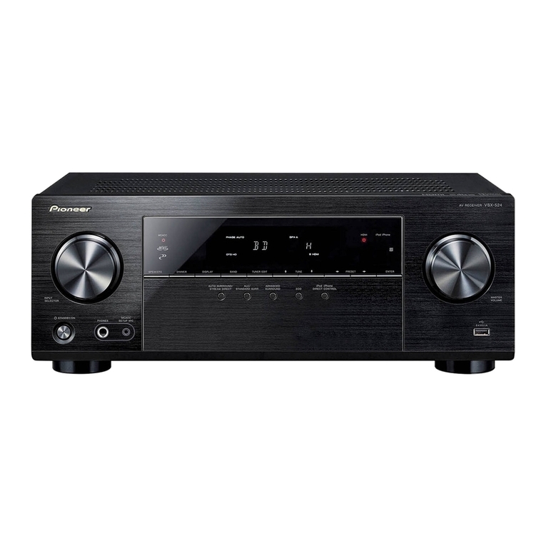
Pioneer DMH-A5450BT User manual

Pioneer

Pioneer DMH-A5450BT User manual

Pioneer AVH-Z3200DAB User manual

Pioneer

Pioneer AVH-Z3200DAB User manual

Pioneer AVH-G215BT User manual

Pioneer

Pioneer AVH-G215BT User manual

Pioneer AVH-210EX User manual

Pioneer

Pioneer AVH-210EX User manual

Pioneer Elite VSX-LX102 Installation guide

Pioneer

Pioneer Elite VSX-LX102 Installation guide

Pioneer DMH-A241BT User manual

Pioneer

Pioneer DMH-A241BT User manual

Pioneer DMH-Z5350TV User manual

Pioneer

Pioneer DMH-Z5350TV User manual

Pioneer DMH-1770NEX User manual

Pioneer

Pioneer DMH-1770NEX User manual

Pioneer Elite VSX-LX104 User manual

Pioneer

Pioneer Elite VSX-LX104 User manual

Pioneer AVH-6300BT User manual

Pioneer

Pioneer AVH-6300BT User manual

Pioneer SX-316-S User manual

Pioneer

Pioneer SX-316-S User manual

Pioneer SX-2700 User manual

Pioneer

Pioneer SX-2700 User manual

Pioneer VSX-534 User manual

Pioneer

Pioneer VSX-534 User manual

Popular Stereo Receiver manuals by other brands

Aiwa Z-HK550 Service manual

Aiwa

Aiwa Z-HK550 Service manual

Rotel RX-7707 owner's manual

Rotel

Rotel RX-7707 owner's manual

Harman Kardon HK3350 owner's manual

Harman Kardon

Harman Kardon HK3350 owner's manual

Technics SA-AX710 Service manual

Technics

Technics SA-AX710 Service manual

Denon AVR-3808CI owner's manual

Denon

Denon AVR-3808CI owner's manual

Denon AVR-1082 Specifications

Denon

Denon AVR-1082 Specifications

JVC JR-S81M Service manual

JVC

JVC JR-S81M Service manual

Sony STR-DA3300ES - Multi Channel Av Receiver operating instructions

Sony

Sony STR-DA3300ES - Multi Channel Av Receiver operating instructions

Yamaha RX-830 owner's manual

Yamaha

Yamaha RX-830 owner's manual

Nakamichi RE-2 Service manual

Nakamichi

Nakamichi RE-2 Service manual

Insignia NS-R2001 user guide

Insignia

Insignia NS-R2001 user guide

Philips US2-PH61153 user manual

Philips

Philips US2-PH61153 user manual

Denon AVR-X6300H Service manual

Denon

Denon AVR-X6300H Service manual

RCA Digital Satellite Receiver user guide

RCA

RCA Digital Satellite Receiver user guide

Kenwood KRF-X9050D instruction manual

Kenwood

Kenwood KRF-X9050D instruction manual

Harman Kardon HK690I Technical manual

Harman Kardon

Harman Kardon HK690I Technical manual

Yamaha R-5 Service manual

Yamaha

Yamaha R-5 Service manual

Denon AVR-X2500H owner's manual

Denon

Denon AVR-X2500H owner's manual

manuals.online logo
manuals.online logoBrands
  • About & Mission
  • Contact us
  • Privacy Policy
  • Terms and Conditions

Copyright 2025 Manuals.Online. All Rights Reserved.