manuals.online logo
Brands
  1. Home
  2. •
  3. Brands
  4. •
  5. Pioneer
  6. •
  7. Stereo Receiver
  8. •
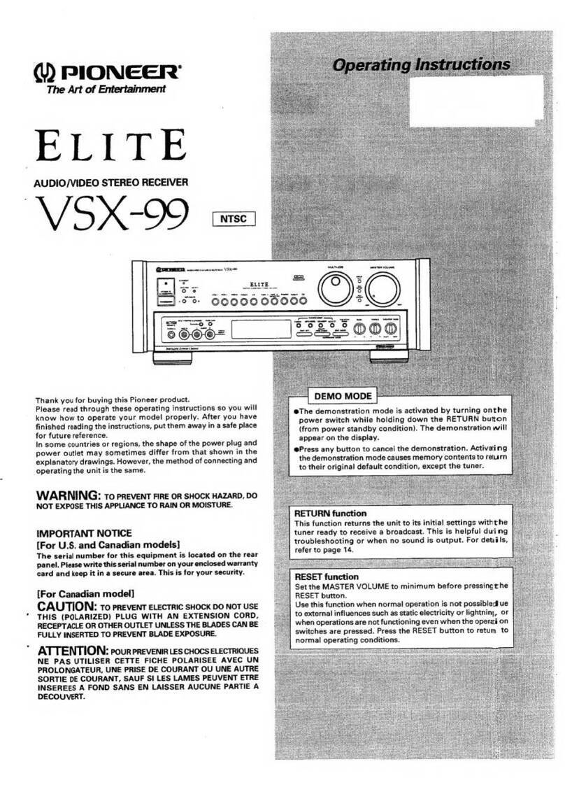
  9. Pioneer VSX-501 User manual

Pioneer VSX-501 User manual

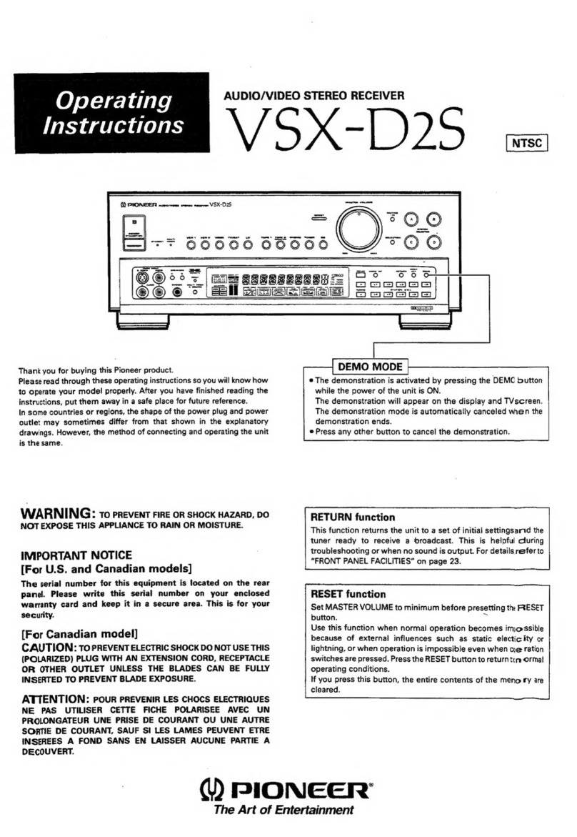
Operating
Instructions
AUDIO/VIDEO
STEREO
RECEIVER
Vo!
Voxolls
_—|
DEMO MODE
|
@
Ilustration
shows
model
VSX-501.
®
The
demonstration
mode
is
activated
by
turning
on
the
power
switch
while
holding
down
the
RETURN
button
(from
power
standby
condition).
The
demonstration
will
appear
on
the
display.
|
e
Press
any
other
switch
to
cancel
the
demonstration.
Thank
you
for
buying
this
Pioneer
product.
Please
read
through
these
operating
instructions
so
you
will
know
how
to
operate
your
model
properly.
After
you
have
finished
reading
the
instructions,
put
them
away
in
a
safe
piace
for
future
reference.
In
some
countries
or
regions,
the
shape
of
the
power
plug
and
power
outlet
may
sometimes
differ
from
that
shown
in
the
explanatory
drawings.
However,
the
method
of
connecting
and
operating
the
unit
is
the
same.
WARNING:
To
PREVENT
FIRE
OR
SHOCK
HAZARD,
DO
NOT
EXPOSE
THIS
APPLIANCE
TO
RAIN
OR
MOISTURE.
IMPORTANT
NOTICE
[For
U.S.
and
Canadian
models]
The
serial
number
for
this
equipment
is
located
on
the
rear
panel.
Please
write
this
serial
number
on
your
enclosed
warranty
card
and
keep
it
in
@
secure
area.
This
is
for
your
security.
Note
to
CATV
system
installer
This
reminder
is
provided
to
call
the
CATV
system
installer’s
attention
to
Article
820-40
of
the
NEC
that
provides
guidelines
for
proper
grounding
and,
in
particular,
specifies
that
the
cable
ground
shall
be
connected
to
the
grounding
system
of
the
building,
as
close
to
the
point
of
cable
entry
as
practical.
[For
Canadian
model]
CAUTION:
To
PREVENT
ELECTRIC
SHOCK
DO
NOT
USE
THIS
(POLARIZED)
PLUG
WITH
AN
EXTENSION
CORD,
RECEPTACLE
OR
OTHER
OUTLET
UNLESS
THE
BLADES
CAN
BE
FULLY
INSERTED
TO
PREVENT
BLADE
EXPOSURE.
:
ATTENTION:
pour
PREVENIR
LES
CHOCS
ELECTRIQUES
NE
PAS
UTILISER
CETTE
FICHE
POLARISEE
AVEC
UN
PROLONGATEUR
UNE
PRISE
DE
COURANT
OU
UNE
AUTRE
SORTIE
DE
COURANT,
SAUF
SI
LES
LAMES
PEUVENT
ETRE
INSEREES
A
FOND
SANS
EN
LAISSER
AUCUNE
PARTIE
A
DECOUVERT.
RETURN
function
This
function
returns
the
unit
to
a
set
of
initial
settings
and
ready
|
to
broadcast
tuner.
This
is
helpful
during
troubleshooting
or
when
|
no
sound
is
output.
For
details,
refer
to
page
19.
W)
PIONEER’
The
Art
of
Entertainment
|
IMPORTANT
The
hghtning
flash
yath
arrawhea
pa
an
equilateral
9
intended
to
alert
the
19
the
preseace
of
uningulated
“dangerous
voltage’
within
the
product's
enclosure
that
may
be
of
sufticent
mageiturda
to
constitute
ansk
of
electric
shock
tw
persons
Ow
READ
INSTRUCTIONS
~
All
the
safety
and
operating
instructions
shoutd
be
read
before
the
appliance
is
operated
RETAIN
INSTRUCTIONS
~
The
safety
and
operating
instructions
should
be
retained
for
future
reference
HEED
WARNING
~
Ali
warnings
on
the
apptiance
and
in
the
operating
instructions
should
be
adhered
to.
CAUTION
RISK
OF
ELECTRIC
SHOCK
OO
NOT
OPEN:
CAUTION:
TO
PREVENT
THE
RISK
OF
ELECTRIC
SHOCK,
DO
NOT
REMOVE
COVER
(OR
BACK.
NO
USER
SERVICEABLE
PARTS
INSIDE.
REFER
SERVICING
TO
QUALIFIED
SERVICE
PERSONNEL.
—
SAFETY
INSTRUCTIONS
—
POWER
LINES
=
An
outdoor
antenna
should
be
iocated
away
from
power
lines.
NONUSE
PERIODS
~
The
power
cord
of
the
appliance
should
be
unplugged
from
the
outtet
when
left
unused
for
a
long
period
of
time
OBJECT
AND
LIQUID
ENTRY
~
Care
should
be
taken
80
that
objects
do
not
fall
and
liquids
are
not
spilted
into
the
enclosure
through
openings
The
exclamation
poi
within
aq
equilateral
intended
to
alert
operating
and
angie
is
nce
of
important
g)
instructions
in
appliance
OUTDOOR
ANTENNA
GROUNDING
~
ff
an
outside
antenna
is
connected
to
the
antenna
terminal,
be
sure
tha
antenna
system
is
grounded
so
3s
to
provide
some
protection
against
voltage
surges
ang
built-up
static
charges.
in
the
U.S.A.
section
819
of
the
National
Electrical
Code,
ANSI/NFPA
70,
provides
intormation
with
respect
to
proper
grounding
of
the
mast
and
FOLLOW
INSTRUCTIONS
All
operating
and
use
instructions
should
be
followed
WATER
AND
MOISTURE
~
The
appliance
should
not
DAMAGE
REQUIRING
SERVICE
~
The appliance
should
be
serviced
by
@
Pionser
authorized
service
center
or
qualified
service
personnel
when:
supporting
structure,
grounding
of
the
lead-in
wire
to
an
antenna
discharge
unit,
size
of
grounding
conductors,
location
of
antenna
discharge
unit,
be
used
near
water
~
for
example,
near
a
bathtub,
The
power-supply
cord
or
the
phig
has
been
connection
to
grounding
electrodes,
and
washbowl,
kitchen
sink,
laundry
tub,
in
a
wet
damaged.
requirements
for
the
grounding
electrode.
See
Fig.
basement,
or
near
a
swimming
pool,
ete
Objects
have
fallen,
or
liquid
has
been
spilled
into
A
LOCATION
--
The
appliance
should
be
installed
in
a
stable
location.
WALL
OR
CEILING
MOUNTING
—
The
appliance
should
not
be
mounted
to
3
wall
or
calling.
or
exhibits
8
marked
change
In
pertorman:
VENTILATION
~
The
appliance
shoutd
be
situated
so
The
appliance
has
been
dropped
or
the
enclosure
that
its
location
or
position
does
nat
interfere
with
damaged.
its
proper
ventilation,
For
example,
the
appliance
SERVICING
~
The
user
should
not
attempt
to
service
should
not
be
situated
on
a
bed,
sofa,
rug,
or
similar
the
appliance
beyond
that
described
in
the
surface
that
may
block
the
ventilation
openings;
or,
aperating
instructions.
All
other
servicing
should
placed
in
a
built-in
installation,
such
as
a
bookcase
be
referred
to
qualified
service
personnel
or
cabinet
that
may
impede
the
flow
of
air
through
the
ventilation
openings
HEAT
~
The
appliance
should
be
situated
away
trom
ae
3
heat
sources
such
as
radiators,
heat
registers,
a
ee
if
=
stoves,
or
other
appliances
{including
amplifiers}
NEC
—~
NATIONAL
ELECTRIC
CODE
Es
that
produce
heat,
.
CART
~
An
appliance
and
cart
combination
should
be
moved
with
care.
Quick
stops,
excessive
force,
and
uneven
surfaces
may
cause
the
appliance
and
cart
combination
to
overturn
the
appliance,
The
appliance
has
been
exposed
to
cain.
The
appliance
does
not
appear
ta
operate
normally
POWER
SOURCES
—
The
appliance
should
be
ae
connected
to
a
power
supply
only
of
the
type
2
described
in
the
operating
instructions
or
as
ANTENNA
marked
on
the
appliance
:
POWER-CORD
PROTECTION
~
Powersupply
cords
LEAD
IN
should
he
routed
so
that
they
are
not
likely
to
be
ee
WIRE
4
walked
on
or
pinched
by
items
placed
upon
or
we
against
them.
Pay
particular
attention
to
cords
at
“
plugs,
convenience
receptacles,
and
the
paint
eS
ANTENNA
i
where
they
exit
from
the
appliance.
——
DISCHARGE
UNIT
q
POLARIZATION
-
Hf
your
purchased
product
is
INEC
SECTION
810
20)
provided
with
a
polarized
power
plug,
please
read
the
following
instructions.
This
productis
equipped
with
a
polarized
alternating
current
ling
plug
(2
plug
SERVICE
having
one
blade
wider
than
the
other),
This
plug
~
will
fit
into
the
power
outlet
only
one
way.
This
is
a
safety
feature.
If
you
are
unable
to
insert
the
plug
fully
into
the
outlet,
try
reversing
the
plug.
If
the
plug
should
still
fail
to
fit,
contact
your
electrician
to
replace
your
obsoleté:
outlet,
Do
not
defeat
the
safety
purpose
of
the
polarized
plug
CLEANING
~
The
appliance
should
be
cleaned
only
with
a
polishing
cloth
or
a
soft
dry
cloth,
Never
clean
with
furniture
wax,
benzine,
insecticides
or
other
volatile
liquids
since
they
may
corrode
the
cabinet,
GROUNDING
CONDUCTORS
{NEC
SECTION
810
—
21)
POWER
SERVICE
GROUNDING
ELECTRODE
SYSTEM
FIG.
A
(NEC
ART
250,
PART
H}
i
2
<ARBI378>
CONTENTS
BEFORE
OPERATING,
ADJUST
THE
POSITION
OF
THESE
SWITCHES
.......00.
cere
4
PEA
DURES
sy
ccesk
ave
eta
eereie
ines
ds
pleinted
cisbocaddtedtanads
uti
aeantceiied
anna
tunes
5
ACCESSORY
ITEMS
5
BLOCK
DIAGRAM
«
cessis
cacavsiepaieaeiv
es
Ges
dedptesecsianint
prtassutindentisereaueresatea
sitareaasatwendane
6
SUBROUND.
EFFECT
cisieacnusitn
spuernsansatduaduaassnsbiUsyssuvins
craves
tiabieayseniiibouseedss
qienta
sae
6G
6
7
7
7
ERGLBY
SO
OGG
az
cviewaseeane
dua
encieertih
vanseivensiadcavsucdarninenveds
eniyee
te
DOLBY
PRO
LOGIC
SURROUND,
DOLBY
3CH
LOGIC
CENTER
MODE
...........cccssececeeecsneeeeeeeeeeeeee
SPEAKER
INSTALLATION
\oussancasersosinist
vccinsalsgaesnetuovvieyestekeunanbiadyeg
haa
cagieGvadeaanins
Sioa
setuiaenge
he
SIMULATED:
STEREO
tacuctsaccetetasasv
ester
cuctasss
thie:
Setsenadevewgeiens
roveremanansa
cel
oud
eoeseceactledtsvyi¥eentece
ees
OAT
IOMMLOI
ESM
hse civ
an
siecvatva
ca
tactenn
ciserieaucnevdiesiveuadssianihaCienneetasdicetenn
thd
(eeadeshlonsibeenemdbraedes
8
Basic
audio
system
connections
...
Basic
video
system
connections
Speaker
connections...........:5
Applications......
Multi-Roam
connections
....
REAR
PANEL
FACILITIES
iam
FRONT
PANEL
FACILITIES
[aR
RRRRnnnrr
rr
MNS
eM
cesta
cena
tlss
co
ueud
bn
coeeddeneuscndineaevassecousbaisvoeucccetga
uiiwataneceaceaveesdacuaticecee
vale
bleaiacveiece
21
DIRECT-
ACCESS:
TONIN
Giivvesnevtasczses
evacuate
vex
cauins
cmesdexcevesiegveineeasas
aesas
Sivediaendeasadsacedevovenehens
21
AUTO
TUNING.........
Perera
MANUAL
TUNING...
cisscccscteecnccasideverreceecseeter
wee
22:
PRESET
TUNING
aie
ww
22
HITS
(Hyper
Intelligent
Tuning
System)
.....
eee
RECEIVING
FM
SIMULCAST
TV
PROGRAMS
.......cccscccsseeeeereeeeeaeeeeenesecunneesoreseees
24
OPERATING
THE
AUDIO/VIDEO
COMPONENTS
[RiRRResssnsnnnnnnnnnnnnESSS
SESE
EEEEEEES
ES
Seen
ESS
tS
STESES
24
PLANIBACK
sascseiscateaiiss
este
stactecdeousees
seh
eretivanaupeaudeds
bees
oa
dsesinibeW
usta
cs
teussaai’
capivedeosaeceasestaasvene
RECORDING
WITH
A
CASSETTE
DECK
VIDEO-RECORDING
....,
csssevessiveswiesingdustadeade
vines
bawvicllaehen
ales
deus
ache
bus eas
eete
teh
iualvedes
aecanteatee
agin
one
NRE
AUN
wea
ton
on
26
EO
ee
ee
ee
ne:
26
Bia
hacstenac
ihe
dace
sepcpeee
theca
Nt
tg
Ue
27
leer
ste aad
ane
te
eect
28
HINTS“FOR:BET
TER
RECEPTION:
sass
ccctics
scexsnchnkaader
vases
terstiescodsadagernacendhcevendchoradeddusiisscateeace
29
rene
na
Na
ne
Mao
tee
30
Pe
men
an
eke
PONS
anne
rN
36
RECEIVE:
CONTEOL
DUTTON
oases
isic
cab
ee
sv
sveedeoeescacsadvn
ced tac
vaeecascuvilvus
Gased
seve
Veoaved
canes
wesidedaisvegvesans
36
Operating
other
components..
aoe
PFOGraMMIng
....seeeceees
eens
TROUBLESHOOTING
...
SPECIFICATIONS.)
sicsccse
lesan
aia
shaayensunusaaapeaeeue
ceva
ue
Dena
peuenes
mabe
ith
deebrs
abeteer
ia
eStameaai
eed
needa
tien
3
<ARB1378°>
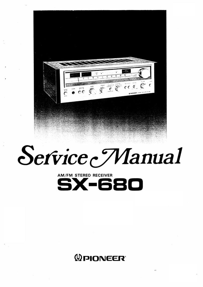
[TWO
VOLTAGE
SELECTOR
SWITCHES
|
Only
multi-voltage
modeis
are
provided
with
these
switches.
U.S.,
Canadian,
European,
U.K.
and
Australian
models
are
not
provided
with
these
switches.
Mains
voltages
in
Saudi
Arabia
are
127
V
and
220
V
only.
Never
use
this
model
with
110
V
setting
in
Saudi
Arabia.
The
line
voltage
selector
switches
are
on
the
rear
panel.
Before
your
model
is
shipped
from
the
factory,
these
switches
are
set
to
the
power
requirements
of
the
destination.
Check
that
they
are
set
properly
before
plugging
the
power
cord
into
the
household
wail
socket.
If
the
voltage
is
not
properly
set
or
if
you
move
to
an
area
where
the
voltage
requirements
differ,
adjust
the
selector
switches
as
follows.
1.
Use
a
medium-size
screwdriver.
2.
First,
insert
a
screwdriver
in
the
groove
of
the
voltage
selector
at
the
right,
and
adjust
so
that
the
tip
of
the
groove
points
to
the
voltage
value
of
your
area.
3.
Next,
insert
a
screwdriver
in
the
groove
of
the
voltage
selector
at
the
jeft
and
adjust
until
the
voltage
is
the
same
as
at
the
right.
TWO
VOLTAGE
SELECTORS
110V
120-127V
gfe
220V
240V
11O¥
120-427V
SEE
INSTRUCTION
MANUAL
CAUTION:
TWO
VOLTAGE
SELECTORS
ac
tov
|
AC
120
T
ac
220
|
ac
240v
Dr
@y Or
110V
|
120-127¥
|
220V
TeV
1200-1274
x
A
-Y
cu
ie
x«K
NOTE:
Both
switches
must
be
in
the
same
switch
setting;
otherwise,
unit
can
be
damaged.
VOLTAGE
SELECTORS
4
<ARB1378>
BEFORE
OPERATING,
ADJUST
THE
POSITION
OF
THESE
SWITCHES
CHANNEL
STEP/FM
DE
EMPHASIS
SWITCH
|
(Not
available
on
U.S.
and
Canadian
models)
The
unit
has
been
factory
preset
to
the
channel
allocation
and
de-
emphasis
value
for
the
area
in
which
it
is
to
be
sold,
if
these
values
are
set
incorrectly,
the
frequency
display
may
stop
at
the
wrong
frequency,
or
sound
may
be
distorted,
resulting
in
an
inability
to
reproduce
reception
signals
at
their
proper
sound
quality.
For
this
reason,
be
sure
to
confirm
that
the
values
are
set
correctly
before
first
using
the
unit.
[100
kHz/10 kHz/75
ys]
position:
Set
to
this
position
for
areas
with
an
FM
reception
step
of
100
kHz,
AM
10
kHz,
and
de-emphasis
75
xs.
{50
kHz/9
kHz/50
us)
position:
Set
to
this
position,
for
areas
with
an
FM
reception
step
of
50
KHz,
AM
9
kHz,
and
de-emphasis
50
ys.
NOTE:
When
unsure
about
the
channel
allocation
and
de-emphasis
values
for
your
area,
consult
your
dealer
for
correct
information.
CHANNEL
STEP/
FM
DE-
EMPHASIS
SOkHz
/50uS
—@
e~
SkHz
100kHz—~®
®-10kHz
{75x48
FM
AM
|
FEATURES
The
VSX-501/VSX-511S
combines
the
functions
of
receiver,
wireless
remote
control,
audio-visual
selector
and
surround
processor.
It
will
play
a
central
role
in
your
enjoyment
of
audio-video
media.
®
BUILT-IN
DIGITAL
DELAY,
DOLBY
SURROUND
CIRCUIT
You
can
enjoy
STUDIO
and
SIMULATED
surround
playback.
And
thanks
to
the
built-in
DOLBY
PRO
LOGIC
SURROUND
decoder,
you
can
also
enjoy
the
superb
imaging
and
sensation
of
movement
provided
by
DOLBY
SURROUND
when
using
software
bearing
the
DO
[porsy
suarounn
|
mark.
{When
not
using
rear
speakers,
DOLBY
3CH
LOGIC
lets
you
enjoy
the
ambience
of
a
wide,
spacious
sound
field.)
With
SIMULATED
and
DOLBY
PRO
LOGIC
SURROUND,
changing
the
delay
time
lets
you
enjoy
a
wider
sound
field
effect.
*¢
LARGE,
MOTOR-DRIVEN
VOLUME
KNOB
The
large
volume
knob
contributes
to
operational
convenience
and
positive
response,
You
can
even
operate
it
via
remote
control.
When
you
change
the
volume
setting
using
the
remote
control
unit,
the
knob
turns
by
itself,
making
it
easy
to
keep
track
of
the
current
setting.
@
VIDEO
SIGNAL
SELECTOR
(Simulcast
function)
Allows
free
combination
of
various
audio-visual
sources
during
playback
and
over-dubbing,
enabling
you
to
produce
your
own
origina!
video
product.
©
TWO-WAY
VCR
COPYING
AND
MONITORING
VCR
1
—
VCR
2:
Copying
of
video
cassette
tapes
can
be
performed
in
either
direction.
a
LD
—
VCR
1,
VCR
2:
Allows
simuttaneous
production
of
two
copies
from
video
disc
or
compact
disc
with
video.
®
ACOUSTIC
MEMORY
FUNCTION
Five
types
(A—E)
of
tone
control
settings
can
be
preset.
The
settings
for
loudness
and
flat
tone
response
functions
can
also
be
selected
quickly.
°
CUSTOM
MEMORY
FUNCTION
Stations
can
be
preset
according
to
the
genre
of
the
material
broadcast,
and
Memory
Scan
of
a
particufar
genre
can
be
carried
out.
®
90/60/30-MINUTE
SLEEP
TIMER
FUNCTION
®
MULTI-ROOM
REMOTE
JACK
The
optional
MR-100
Multi-room
remote
control
unit
can
be
connected
to
the
Multi-room
remote
IN
jack.
[VSX-501]
*
AV
REMOTE
CONTROL
UNIT
With
the
attached
remote
controi
unit
you
can
operate
any
Pioneer
audio
or
video
component
bearing
the
isa
mark.
{VSX-517S]
®
AV
PROGRAMMABLE
REMOTE
CONTROL
UNIT
With
the
attached
programmable
remote
control
unit,
you
can
operate
any
Pioneer
audio
or
video
component
bearing
the
if
you
use
the
LEARN
function,
remote
commands
of
components
not
bearing
the
ff]
mark
can
be
memorized,
giving
you
remote
control
over
a
component's
functions.
You
can
also
use
the
MULTI-COMMAND
to
memorize
up
to
seven
commands
in
order,
letting
you
transmit
them
at
the
push
of
a
single
button.
|
>
CCESSORY
ITEMS
FM
T-type
Antenna
AM
Loop
Antenna
VSX-501
Dry
ceil
battery
x
2
(size
“AAA”
(RO3/UM-4))
AWN
remote
control
unit
VSX-511S8
Audio/Video
programmabie
remote
control
unit
Alkaline
dry
cell
battery
x
2
{size
‘AA’
(LR6/AM-3))
5
<ARB1378>
[
|
BLOCK
DIAGRAM
AUDIO
TAPER
REC
Shay
ant
[RE
PHONO
G-{EG
+o
co
G@-———0.
tape
1
~
17
Go
ver
1©
yor
2@——0
ry
@——0
TAPE
@&
—
fed
vers
eet
i
vege
@-—_#
i
Fe
|
=
VIDEO
LD
Qe
ver
Go
VCH
2
Gum
FV
Goren
Ne
————~<f-Fe
Ww
——D
fronton
|
SURROUND
EFFECT
This
unit
has
a
built-in
surround
processor
for
adding
presence
and
an
expansive
effect
to
the
sound.
e
STUDIO:
Select
this
position
to
enjoy
the
effect
of
listening
to
music
in
a
recording
studio.
The
source
sound
is
output
as
it
is
through
the
front
speakers,
with
reverberation
output
through
the
rear
speakers.
This
is
particularly
suitable
for
a
source
that
has
a
lot
of
reverberation.
e
SIMULATED
SURROUND:
The
“SIMULATED”
creates
effects
of
reverberated
and
reflected
sound
from
the
walls
and
ceiling
similar
to
a
concert
hail.
These
sound-effects
added
to
the
actual
sound
from
the
source
make
you
feel
as
if
you
were
in
a
more
expanded
space.
The
different
ranges
of
the
expanded
space
can
be
set
by
the
DELAY
TIME
button.
Set
the
Delay
Time
to
16
ms
or
20
ms
for
a
live-house
concert.
For
chamber
music,
set
to
20
ms.
For
orchestral
music,
set
to
30
ms.
The
“SIMULATED
SURROUND”
also
gives
effects
on
monaural
sources
by
outputting
the
reverberated
sound
from
rear
speakers
while
keeping
the
output
sound
from
front
speakers
as
it
is.
Turn
on
the
“SIMULATED
SURROUND”
for
a
monaural
source
to
gain
effective
surround
playback.
Choose
the
SIMULATED
SURROUND
mode
if
the
source
sound
signal
is
mono.
Little
or
no
sound
will
be
heard
from
the
surround
speakers
if
the
STUDIO
or
DOLBY
PRO
LOGIC
SURROUND
mode
is
selected.
*
DOLBY
PRO
LOGIC
SURROUND
Choose
this
setting
for
movies
and
music
(especially
Video
Discs
and
video
tapes
bearing
the
oo
[poLey
suRRouNO
|
mark)
playback.
DOLBY
PRO
LOGIC
SURROUND
continuously
detects
the
size
and
direction
of
the
dominant
signal
and
cancels
undesirable
crosstalk,
thereby
providing
signal
emphasis.
ft
makes
you
clearly
perceive
the
directions
where
music
comes
from.
Real
flow
of
sound
also
can
be
re-created
naturally
using
this
feature.
You
can
feel
as
if
being
in
the
outstanding
and
expansive
sound
field.
When
using
DOLBY
PRO
LOGIC
SURROUND,
a
delay
time
setting
of
20
ms
is
commonly
used.
Use
a
different
setting
if
you
prefer.
Even
if
they
do
not
bear
the
oo
DOLBY
SURROUND
|
mark,
some
video
recordings
may
be
Dolby
Surround encoded.
Note:
Doiby
Surround
will
not
operate
correctly
if
the
signal
passes
through
a
graphic
equalizer.
When
using
Dolby
Surround,
turn
off
the
TAPE
2
MONITOR
or
set
|
the
graphic
equalizer
for
flat
response
or
to
its
“‘through’’
(or
off)
setting,
if
you
have
one
in
use.
|
|
DOLBY
3CH
LOGIC
Combining
the
rear
speaker
signal
with
that
of
the
front
speakers
results
in
your
being
able
to
enjoy
a
regenerated
sound
field
which
has
comparatively
more
presence
and
a
more
expansive
feeling
from
the
front
3
channels
(front
L,
front
R,
and
center
speakers)
than
that
of
ordinary
stereo
regensration.
DOLBY
3CH
LOGIC
can
be
used
with
stereo
sources
not
encoded
with
DOLBY
SURROUND.
6
<ARBI37B>
Manufactured
under
license
from
Dolby
Laboratories
Licensing
|
Corporation.
Additionally
licensed
under
one
or
more
of
the
following
patents:
U.S.
numbers
3,632,886,
3,746,792
and
3,959,590;
CANADA
numbers
1,004,603
and
1,037,877.
“Dolby”
and
the
double-D
symbol
oo
are
trademarks
of
Dolby
Laboratories
Licensing
Corporation.
Fabriqué
sous
licence
de
Dolby
Laboratories
Licensing
Corporation
et
sous
un
ou
plusiers
des
brevets
suivants;
U.S.A.
3,632,886,
3,746,792,
et
3,959,590;
Canada
1,004,603
et
1,037,877,
DOLBY
et
le
symbole
double-D
Oo
sont
des
marques
de
Dolby
Laboratories
Licensing
Corporation.
You
can
choose
from
the
following
settings:
Center
Mode
Choices:
When
using
a
center
speaker:
¢
NORMAL
—
Low
range
frequencies,
which
have
little
effect
on
directionality
and
positioning,
are
routed
to
the
left
and
right
front
speakers.
So
you
can use
a
relatively
small
size
speaker
as
the
center
speaker.
®
WIDE
~
If
you
use
a
large
size
center
speaker,
choose
this
setting.
The
full
frequency
range
of
the
Dolby
Surround
center
channel,
from
low
to
high,
is
routed
to
the
center
speaker.
DOLBY
PRO
LOGIC
SURROUND,
DOLBY
3CH
LOGIC
CENTER
MODE
When
not
using
a
center
speaker:
DOLBY
PRO
LOGIC
SURROUND
°
PHANTOM
—
The
signal
which
would
have
been
sent
to
the
center
speaker
is
divided
equally
between
the
left
and
right
front
speakers.
With
DOLBY
PRO
LOGIC
SURROUND,
monaural
source
sound
will.
be
heard
only
from
the
center
channe
at
settings
other
than
the
PHANTOM
position.
SPEAKER
INSTALLATION
To
get
the
most
out
of
the
surround
system,
place
the
speakers
as
shown
below.
An
example
of
speaker
positioning
Front
right
speaker
Center
speaker
Yi
FRONT
Listening
Lz
Rear
left
Rear
right
speaker
speaker
f
the
rear
speakers
are
positioned
at
an
extreme
distance,
the
surround
level
becomes
unable
to
adjust
and
the
surround
effect
will
not
be
fully
achieved.
NOTE:
©
To
avoid
interference
with
the
picture
on
a
nearby
TV
set,
use
magnetically
shielded
speaker
systems.
This
is
particularly
important
for
the
center
speaker
since
it
is
usually
focated
closest
to
the
TV.
°
Position
the
left
and
right
channel
speakers
at
equal
distances
from
the
TV
set
and
approximately
six
feet
from each
other.
*
Position
the
center
speaker
above, below,
or
behind
the
TV
set.
Sound
may
not
appear
to
coincide
with
the
picture
if
you
position
it
next
to
the
TV
set.
®
Rear
speakers
are
best
positioned
slightly
above
ear
fevel.
_
SIMULATED
STEREO
This
function
transforms
monaural
signals
into
simulated
stereo
sound.
Use
it
when
you
wish
to
experience
a
sense
of
stereo
presence
when
istening
to
AM
broadcasts,
and
other
monaural
signal
sources.
NOTE:
The
simulated
stereo
function
can
also
be
used
with
stereo
sound
sources,
but
it
will
result
in
an
effect
somewhat
different
from
the
normal
stereo
sound,
7
<ARB1378>
CONNECTIONS
Setting
Up
the
AM
Antenna
*
insert
the
claw
on
the
bottom
of
the
antenna
into
the
groove
in
the
teg.
®
Place
the
antenna
on
a
level
surface
and
rotate
it
to
locate
the
orientation
that
yields
the
best
reception.
*
Use
the
attachment
hole
in
the
leg
to
screw
to
wall
or
other
location,
then
insert
the
claw
on
the
bottom
of
the
antenna
into
the
groove
in
the
feg
(fixing
the
antenna
in
the
direction
that
gives
the
best
reception).
Lead
wire
Lead
wire
POWER-CORD
CAUTION
Precaution
regarding
installation
position
of
cassette
deck.
If
the
cassette
deck
is
installed
in
the
(4)
positions
shawn
in
the
drawing
beiow,
it
may
be
adversely
affected
during
playback.
If
possible,
it’s
better
to
install
it
in
the
@
position.
Handle
the
power
cord
by
the
piug.
Do
not
pull
out
the piug
by
tugging
the
cord
and
never
touch
the
power
cord
when
your
hands
are
wet
as
this
could
cause
a
short
circuit
or
electric
shock.
Do
not
place
the
unit,
a
piece
of
furniture,
etc.,
on
the
power
cord,
or
pinch
the
cord.
Never
make
a
knot
in
the
cord
or
tie
it
with
other
cords.
The
power
cords
should
be
routed
such
that
they
are
not
likely
to
be
stepped
on.
A
damaged
power
cord
can
cause
fire
or
give
you
an
electrical
shock.
Check
the
power
cord
once
in
a
while.
When
you
find
it
damaged,
ask
your
nearest
PIONEER
authorized
servicé
center
or
your
dealer
for
a
replacement.
8
<ARB1378>
CONNECTIONS
|
BASIC
AUDIO
SYSTEM
CONNECTIONS
NOTE
FOR
FIM
1
TYPE
ANTENNA
Stretch
the
antenna
out
to
its
full
length,
and
affix
it
to
a
wall,
etc.
NOTE
FOR
AM
LOOP
ANTENNA
The
antenna
should
be
placed
at
a
distance
from
the
receiver,
and
should
not
be
allowed
to
touch
metallic
objects.
Avoid
placing
it
near
CD
players,
personal
computers,
television
sets,
and
other
devices
generating
radio
frequencies.
Accessory
FM-T
type
antenna
Accessory
AM
Loop
antenna
Turntable
-
||
fee
Pal
Turntable
Cassette
deck
‘oS
{Power
cord
connection
example]
9
<ARBI378>
|
CONNECTIONS
"BASIC
VIDED
svsTEM
CONNECTIONS
TV
monitor
VIDEO
AUDIO
OUT
y
>
TV
tuner
FO
re
ree
10
<ARB1378>
CONNECTIONS
SPEAKER
CONNECTIONS
Center/Rear
speaker
cord
Pe.
connection
qo
en
@
Push
the
lever
down.
@®
@®
Insert
the
cord.
©
Puil
the
fever
back.
NOTE:
Use
speakers
of
impedance
8
2
~
16
2.
Va
Front
speaker
cord
connection
@
Push
and
keep
the
lever
up
(or
down).
@)
Insert
the
cord.
@
Release
the
lever.
NOTE:
When
connecting
a
super
wooter
system
such
as
the
Pioneer
S-W1000,
cannect
it
to
the
same
speaker
terminals
(A
or
B)
to
which
the
front
Speakers
are
connected.
Connecting
the
front
speakers
and
super
woofer
system
to
terminals
A
and
B
respectively
will
result
in
reduced
volume
from
the
front
speakers.
REAR
Front
(R)
Super
woofer
Front
(L)}
11
<<ARB1378>>
CONNECTIONS
APPLICATIONS
NOTE:
DOLBY
PRO
LOGIC
SURROUND
and
DOLBY
3CH
LOGIC
will
not
operate
correctly
if
the
signal
passes
through
a
graphic
equalizer.
When
using
DOLBY
PRO
LOGIC
SURROUND
or
DOLBY
3CH
LOGIC,
turn
off
the
TAPE
2
MONITOR
button
or
set
the
graphic
equalizer
for
flat
response
or
to
its
““through’’
(or
off}
setting,
if
you
have
one
Cassette
deck
2
inuse
ss
aca
When
using
a
graphic
equalizer
i
ye
io
Pa
A
a
ee
ete
wade
‘
me
i
i
ee
1
(@.@)
ao
+
!
1
Herel!
|
|
1
H
t
\
<
ar)
R
els
2
ap
!
INPUT
OUTPUT.
H
:
1
'
Graphic
equalizer
H
7
i
1
'
!
QUT
H
i
i
i
i
{
From
L
and
R
To
Land
R
i
{
REC
jacks
PLAY
jacks
!
rn
57)
5
say
a
(PLAY)
OUT
(REC)
IN
12
<ARBI378>
CONNECTIONS
|
;
MULTI-ROOM
CONNECTIONS
NOTE:
Be
careful
not
to
make
the
wrong
connections
for
CONTROL
IN/OUT
{black}
and
MULTI-
ROOM
REMOTE
IN
(green).
[Set-up
example]
©
if
you
connect
to
the
CONTROL
jacks
of
other
components,
such
as
a
CD
player
or
cassette
deck,
bearing
th
mark,
you
can
also
enjoy
remote
contro!
of
these
components
from
Sub
Room.
(For
details
concerning
connections,
refer
to
page
15.)
or
VSX-5118)
ae
teas:
NN
Main
Room
ae
~
VSX-501/VSX-511S
*
Illustration
shows
U.S.
and
Canadian
models.
Main
Room
|
|
Speaker
(L}
TV
monitor
13
<ARB1378>
REAR
PANEL
FACILITIES
OO
®8
®
@FM/AM
ANTENNA
terminals
Use
these
antenna
terminals
for
reception
of
normal
FM
and
AM
broadcasts.
@
TAPE
2
MONITOR
jacks
Connect
the
second
cassette
deck
to
these
jacks.
Connecting
for
Recording
The
tape
recording
jack
{REC}
on
the
cassette
deck
should
be
connected
to
the
REC
side
of
the
TAPE
2
MONITOR
jack
on
the
receiver
with
a
pin
plug
connecting
cord.
Connecting
for
Playback
Connect
the
TAPE
PLAY
jack
on
the
cassette
deck
to
the
PLAY
side
of
the
TAPE
2
MONITOR
jack
on
the
receiver
with
a
pin
plug
connecting
cord.
@
TAPE
1/DAT
jacks
Use
these
to
connect
the
first
cassette
deck
or
DAT
(digital
audio
tape}
deck,
Connecting
for
Recording
The
tape
recording
jack
(REC)
on
the
cassette
deck
or
DAT
should
be
connected
to
the
REC
side
of
the
TAPE
1/DAT
jack
on
the
receiver
with
a
pin
plug
connecting
cord.
Connecting
for
Playback
Connect
the
PLAY
jack
on
the
cassette
deck
or
DAT
to
the
PLAY
side
of
the
TAPE
1/DAT
jack
on
the
receiver
with
a
pin
plug
connecting
cord.
14
<ARB1378>>
FRONT
GAEAKERS
@
VIDEO
OUT
(TV
MONITOR)
jack
Connect
to
monitor
TV
or
to
TV
sets
with
video
input
terminals
for
watching
program
materials
from
a
VCR
1,
2
or
LD
player
connected
to
this
unit.
®VECR
2
jacks
(VIDEO
OUT]
When
copying
program
material
from
the
video
component
connected
to
the
VCR
1
or
LD
jacks,
connect
to
the
VIDEO
INPUT
jacks
of
the
VCR
used
for
recording.
AUDIO
OUT
iL,
Ril
When
copying
program
materials
from
the
video
component
connected
to
the
VCR
1
or
LD
jacks,
or
when
recording
music
from
an
audio
component
source,
connect
to
the
AUDIO
INPUT
jacks
of
the
VCR
used
‘or
recording.
VIDEO
IN]
When
monitoring
the
video
image
from
a
VCR
used
for
copying,
connect
its
VIDEO
OUTPUT
jacks
here.
[AUDIO
IN
(L,
R}}
When
monitoring
the
audio
channe!
from
a
VCR
used
for
copying,
connect
its
AUDIO
OUTPUT
jacks
here.
REAR
PANEL
FACILITIES
(6)
VCR
1
jacks
[VIDEO
OUT]
Wien
copying
program
material
from
the
video
component
connected
to
the
VCR
2
or
LD
jacks,
connect
to
the
VIDEO
INPUT
jacks
of
the
VCR
used
for
recording.
{AUDIO
OUT
IL,
R}}
When
copying
program
material
from
the
video
component
connected
to
the
VCR
2
or
LD
jacks,
or
when
recording
music
from
an
audio
component
source,
connect
to
the
AUDIO
INPUT
jacks
of
the
VCR
used
for
recording.
[VIDEO
IN]
When
monitoring
the
video
image
from
a
VCR
used
for
playing,
connect
its
VIDEO
OUTPUT
jacks
here.
{AUDIO
IN
(L,
R)T
When
monitoring
the
audio
channel
from
a
VCR
used
for
playing,
connect
its
AUDIO
OUTPUT
jacks
here.
7)
CENTER
SPEAKER
terminals
Connect
the
center
speaker
to
these
terminais.
NOTE:
Do
not
allow
any
of
the
cord’s
conductors
to
protrude
from
the
terminals
or
touch
any
other
conductors.
Malfunctioning
or
breakdowns
may
occur
when
conductors
come
into
contact
with
each
other.
Use
center
speakers
of
impedance
8
2-16
Q.
(8)
REAR
SPEAKERS
terminals
Connect
the
rear
speakers
to
these
terminals.
NOTE:
Do
not
allow
any
of
the
cords
conductors
to
protrude
from
the
terminals
or
touch
any
other
conductors.
Malfunctioning
or
breakdowns
may
accur
when
conductors
come
inta
cantact
with
each
other.
Use
rear
speakers
of
impedance
8
0—16
2.
(8)
FRONT
SPEAKERS
terminals
A:
Connect
to
the
first
set
of
speakers.
8:
Connect
to
the
second
set
of
speakers.
Speaker
lead
wire
preparation
and
connection.
NOTE:
De
not
allow
any
of
the
cord’s
conductors
to
protrude
from
the
terminals
of
touch
any
other
conductors,
Malfunctioning
or
breakdowns
may
occur
when
conductors
come
into
contact
with
each
other.
Use
speakers
of
impedance
8
0—16
Q.
G3
PHONO
input
jacks
Connect
to
the
output
cables
from
a
turntable.
@)
GND
terminal
Connect
the
turntable
ground
lead
to
this
terminal.
49
CD
input
jacks
Connect
to
the
output
jacks
of
a
compact
disc
player.
(TV
jacks
(input)
{Use
these
jacks
if
you
wish
to
connect
a
TV
tuner
with
both
video
and
audio
outputs.
{VIDEO
IN]
Connect
the
TV
tuner’s
VIDEO
OUTPUT
to
this
jack.
{AUDIO
IN
(L,
Ri
Connect
the
TV
tuner’s
AUDIO
OUTPUT
to
these
jacks.
LD
jacks
[VIDEO
IN]
When
watching
the
video
image
from
a
LD
player,
connect
its
VIDEO
OUTPUT
jacks
here.
[AUDIO
IN
(L,
R)
When
playing
back
the
audio
channel
from
a
LD
player,
connect
its
AUDIO
OUTPUT
jacks
here.
@
CONTROL
IN/OUT
jacks
IN:
Connect
this
jack
to
other
Pioneer
components
(main
unit
or
remote
control
unit)
when
using
those
components
to
control
this
unit.
OUT:
Connect
this
jack
to
other
Pioneer
components
when
using
the
remote
control
of
this
unit
ta
control
the
other
components.
NOTE:
The
receiver's
remote
sensor
does
not
function
when
a
plug
is
inserted
in
IN
jack.
To
operate,
point
the
remote
control
unit
at
the
remote
sensor
on
the
component
to
which
the
receiver's
IN
jack
is
connected.
When
using
the
(Si
=
MR-100
@
(isd)
MR-100
my,
See
|
God
>
wae
\
Receiver
f-\
Pioneer
component
bearing
the
gj
mark.
Remote
contro!
i
To
the
CONTROL
IN
unit
Remote
jack
of
the
Pioneer
control
unit
component
bearing
the
Hj
mark.
MULTI-ROOM
REMOTE
IN
jack
Connect
to
the
separately
sold
MR-100
Multi-Room
remote
control
unit.
@
AC
OUTLETS
{U.S.
and
Canadian
modes]
[SWITCHED
TOTAL
100
W
(0.8
A)
MAX}
Power
supplied
through
these
outiets
is
turned
on
and
off
by
the
receiver's
POWER
switch.
Total
electrical
power
consumption
of
connected
equipment
should
not
exceed
100
W
(0.8
A).
[UNSWITCHED
100
W
(0.8
A}
MAX]
Power
flows
continually
to
this
outlet,
regardless
of
whether
the
receiver
is
switched
ON
or
OFF.
Electrical
power
consumption
of
the
connected
equipment
should
not
exceed
100
W
(0.8
A).
The
equipment
should
be
disconnected
by
removing
the
power
plug
from
the
wail
socket
when
not
in
regular
use,
e.g.
when
on
vacation.
[Multi-voltage
model]
SWITCHED
TOTAL
100
W
MAX
Power
supplied
through
these
outlets
is
turned
on
and
off
by
the
receiver's
POWER
switch.
Total
electrical
power
consumption
of
connected
equipment
should
not
exceed
100
W.
UNSWITCHED
100
W
MAX
Power
flows
continually
to
this
outlet,
regardless
of
whether
the
receiver
is
switched
ON
or
OFF.
Electrical
power
consumption
of
the
connected
equipment
should
not
exceed
100
W.
15
<ARB1378>
REAR
PANEL
FACILITIES
NOTE:
*
This
unit
should
be
disconnected
by
removing
the
power
plug
from
the
wall
socket
when
nat
in
regular
use,
e.g.
when
on
vacation.
*
Do
not
connect
appliances
with
high
power
consumption
such
as
heaters,
irons,
or
television
sets
to
these
AC
OUTLETS
in
order
to
avoid
overheating
and
fire
risk.
This
can
cause
the
receiver
to
malfunction.
CAUTION:
DO
NOT
CONNECT
MONITOR
OR TV
SET.
Power
cord
FRONT
PANEL
FACILITIES
*
Illustration
shows
model
VSX-501.
GOD
@
®@ODOODOH
®
D
)
@
OO
®
16
<ARBI378>
FRONT
PANEL
FACILITIES
@
POWER
STANDBY/ON
switch/STANDBY
indicator
This
is
the
switch
for
electric
power.
ON:
When
set
to
the
ON
position,
power
is
supplied
and
the
unit
becomes
operational.
STANDBY:
When
set
to
STANDBY
position,
the
main
power
fiow
is
cut
and
the
unit
is
no
longer
fully
operational.
A
minute
flow
of
power
feeds
the
unit
to
maintain
operation
readiness.
The
STANDBY
indicator
lights
when
the
power
is
STANDBY,
and
goes
out
during
ON.
[Timer
ON/OFF
possible]
When
the
unit
is
switched
ON,
ON/OFF
contro!
can
be
performed
by
means
of
the
optional
timer.
NOTE:
When
the
power
is
initially
turned
ON,
muting
will
be
applied
to
prevent
sound
from
being
output
for
about
5
seconds.
@V-SIGNAL
(VIDEO
SIGNAL)
SELECTOR
button
Use
to
change
the
video
signal
in
sequence
leaving
the
sound
unchanged.
a
ee
ee
The
current
setting
is
shown
by
an
indicator
on
the
display
section.
@
Remote
sensor
@
AUTO
SOURCE
CONTROL
buttons
(See
page
28)
1,
2
buttons:
These
buttons
are
for
memorizing
and
recalling
your
current
settings.
Both
7
and
2
can
be
used
to
memorize
settings.
if
you
connect
another
component,
such
as
a
CD
player,
to
the
CONTROL
OUT
jack
on
the
rear
panel,
the
signals
to
switch
power
on
and
start
play
are
also
transmitted.
MEMORY:
Use
when
memorizing
settings
to
a
1,
2
button.
@®MEMORY
button
(See
page
22)
Pressing
this
button
will
result
in
the
memorization
of
the
current
broadcast
band,
reception
frequency,
and
FM
AUTO/MONO
mode.
This
button
is
also
used
for
custom
memory
operation.
©
CUSTOM
MEMO
SEL
button
(See
page
22)
Recall
a
genre
name
with
this
button.
=
ROCK
—+
POP
—»
JAZZ
—
NEWS
—
orcs
@
SCAN
button
Operate
when
the
INPUT
SELECTOR
is
set
to
TUNER.
Station
frequencies
assigned
to
the
STATION
CALL
buttons
are
tuned
in,
one
after
another,
beginning
with
the
current
station
no.,
for
approximately
5
seconds
each.
The
display
section
SCAN
indicator
will
light.
Press
the
button
again
and
the
tuner
remains
tuned
in
to
the
station
playing
when
the
button
was
pressed
the
second
time.
Station
frequencies
not
assigned
station
numbers
in
the
memory
are
skipped.
When
you
have
selected
s
CUSTOM
MEMORY
genre,
memory
scan
is
performed
on
the
stations
in
that
genre.
@©FM
Mode
AUTO/MONO
button
Use
to
select
the
auto
stereo
mode
or
monaural
mode when
listening
to
FM
broadcasts.
The
monaural
mode
has
been
selected
when
the
FM
MONO
indicator
in
the
display
section
is
lit.
Auto
stereo
mode:
Normally,
eave
in
this
mode
for
reception.
When
a
stereo
FM
broadcast
is
received,
it
will
be
automatically
reproduced
in
stereo.
Monaural
mode:
When
receiving
distant
stations
or
stations
with
weak
broadcast
signals,
the
input
signal
may
be
weak,
thus
resulting
in
increased
noise
during
FM
stereo
broadcasts.
in
this
event,
setting
the
receiver
to
the
monaural
mode
will
reduce
the
noise.
in
this
case,
however,
FM
stereo
broadcasts
will
be
reproduced
in
monaural
sound.
NOTE:
This
button
has
no
effect
an
reception
of
AM
broadcasts.
@
Tuning
buttons
AUTO/MANUAL
tuning
selector
button:
(Page
21,
22)
Use
to
select
the
tuning
mode.
To
select
the
AUTO
tuning
mode,
press
this
button
to
light
the
AUTO
TUNING
indicator
in
the
display
section.
To
select
the
MANUAL
tuning
mode,
switch
off
the
AUTO
TUNING
indicator.
AUTO
tuning
When
the
—
or
+
TUNING
button
is
pressed,
the
receiver
automatically
scans
the
broadcast
station
frequencies.
When
a
broadcast
is
detected,
the
scanning
stops
at
that
frequency.
NOTE:
Pressing
the
TUNING
button
(—
ar
+)
while
scanning
is
taking
place
causes
scanning
to
stop.
MANUAL
tuning
This
lets
you
manually
tune
to
particular
broadcast
frequencies.
Each
press
of
the
+
or
—
button
raises
or
lowers
the
frequency
by
one
tuning
step.
For
continuous
scanning,
keep
the
button
pressed,
then
release
it
to
stop
scanning.
DIRECT
ACCESS
tuning
button:
When
this
button
is
pressed,
the
STATION
CALL
buttons
function
as
ten-key
number
buttons
for
direct
input
of
the
desired
reception
frequency.
Press
again
to
cancel
this
mode.
if
the
input
station
falls
outside
of
the
receiver's
tuning
range,
the
display
section
will
display
a
message:
‘‘UPPER™
if
the
frequency
is
too
high
and
“LOWER”
if
it
is
too
iow
(see
page
21).
HITS
(Hyper
intelligent
Tuning
System)
button:
(Page
23)
Press
this
button,
and
search
automatically
begins
up
and
down
the
frequency
for
stations
that
can
be
received.
When
a
station
that
can
be
received
is
found,
the
search
operation
stops.
7
<ARBI1373>
FRONT
PANEL
FACILITIES
@
STATION
CALL
buttons
Up
to
30
FM
or
AM
stations
can
be
preset
at
random.
These
buttons
are
used
to
preset
and
recall
desired
broadcasting
stations,
FM
AUTO/MONO
mode.
NOTE:
Pressing
a
BAND
button
or
STATION
CALL
button
will
select
TUNER
as
the
source,
regardless
of
what
other
listening
source
or
function
was
selected.
@
SIMULATED
STEREO
button
Press
to
produce
a
simulated
stereo
effect
when
listening
to
monaural
sources
(for
example,
normal
AM
or
TV
broadcasts).
“SIMULATED
STEREO”
appears
on
the
display
section.
NOTE:
°
This
effect
is
not
produced
through
the
rear
speakers.
¢
Use
with
the
SURROUND
MODE
in
the
OFF.
@
SURROUND
MODE
selector
buttens
SIMULATED
SURROUND:
Select
this
setting
when
listening
to
music
or
a
monaural
source,
etc.
With
a
monaural
source,
a
much
better
surround
effect
is
achieved
if
it
ls
used
together
with
SIMULATED
STEREO.
STUDIO:
Select
this
setting
to
enjoy
the
effect
of
listening
te
music
in
a
recording
studio.
DOLBY
PRO
LOGIC
SURROUND:
Select
this
setting
when
watching
video
tapes
or
video
discs
bearing
the
[JU]
[pouay
surrouwo]
mark.
@
BALANCE
buttons
Use
them
to
adjust
the
sound
volume
balance
between
left
and
right
speakers.
L:
Press
to
decrease
the
sound
on
the
right
side.
R:
Press
to
decrease
the
sound
on
the
left
side.
Press
L
and
R
together
to
bring
the
volume
balance
back
to
center.
NOTE:
The
left-right
sound
volume
balance
cannot
be
adjusted
on
the
rear
speakers.
TREBLE
control
buttons
Use
to
adjust
the
high-frequency
level.
Press
the
+
button
to
increase
the
high-frequency
level,
and
the
—
button
to
decrease
it.
The
TONE
indicator
appears
on
the
display
section.
When
both
buttons
(+,
—)
of
the
TREBLE
control
are
pressed
simultaneously,
the
treble
response
will
be
set
to
the
flat
(normal)
condition.
@®
BASS
control
buttons
Use
to
adjust
the
low-frequency
Jevel.
Press
the
+
button
to
increase
the
low-frequency
level,
and
the
—
button
to
decrease
it.
The
TONE
indicator
appears
on
the
display
section.
When
both
buttons
(+,
—)
of
the
BASS
contro!
are
pressed
simultaneously,
the
bass
response
will
be
set
to
the
flat
(normal)
condition.
18
<ARBI378>
@®
DELAY
TIME
button
Operates
when
the
SIMULATED
or
DOLBY
PRO
LOGIC
SURROUND
mode
is
ON.
Switches
to
surround
delay
time
in
8
steps.
For
DOLBY
PRO
LOGIC
SURROUND,
20
ms
is
standard.
Changes
in
2
ms
steps.
@
DOLBY
3CH
LOGIC
button
Select
this
setting
when
stereo-source
regeneration
and
rear
speakers
are
not
connected
and
you
Wish
to
use
the
front
L,
front
R,
and
center
speakers
to
enjoy
audio/visual
material
bearing
the
(0
[pavay
surrouno]
mark.
@
MASTER
VOLUME
contro!
Use
it
to
simultaneously
adjust
the
sound
volume
from
the
front,
center
and
rear
speakers.
@®
PHONES
jack
Connect
the
plug
on
your
headphones
to
this
jack.
Set
all
SPEAKERS
A
and
B
switches
to
OFF
if
you
want
to
cut
the
sound
from
speakers
and
listen
to
it
only
through
the
headphones.
@)
SPEAKERS
buttons
(A,
B)
ROFF
ON
ON/OFF
switches
for
the
A
and
B
speaker
systems.
NOTE:
No
sound
will
be
heard
thorough
the
speakers
when
both
A
and
B
buttons
are
depressed
if
only
one
set
of
speakers
has
been
connected
to
either
A
or
B
SPEAKERS
terminals.
;
@)
BAND
(FM/AM)
button
Use
this
to
switch
between
FM
and
AM
frequency
band
reception.
@
TUNING
buttons
+:
Performs
tuning
from
the
currently
displayed
station
frequency
in
ascending
frequency
order.
-:
Performs
tuning
in
order
of
descending
frequencies.
@
INPUT
SELECTOR
buttons
VCR
1:
Press
when
performing
playback
on
a
first
VCR
unit.
VCR
2:
Press
when
performing
playback
on
a
second
VCR
unit.
LD:
Press
when
performing
playback
on
a
LD
player.
TV:
Press
when
using
a
TV
tuner
connected
to
the
TV
jacks.
TAPE
1/DAT:
Press
when
performing
playback
on
a
DAT
or
cassette
deck.
TAPE
2
MONITOR:
Press
when
performing
playback
on
a
second
cassette
deck
or
second
DAT
and
when
monitoring
recording.
cD:
Press
when
playing
compact
discs
on
a
CD
player.
TUNER:
Press
when
listening
to
radio
broadcasts.
PHONO:
Press
when
playing
records
on
turntable.
FRONT
PANEL
FACILITIES
ACOUSTIC
buttons
(See
page
26)
MEMORY:
Pressing
this
button
will
result
in
the
memorization
of
the
sound
quality
{tone
control
condition).
Press
again
to
cancel
this
mode.
SELECT:
°
This
button
is
used
to
preset
the
five
acoustic
memories
(A—E).
°
This
button
is
aiso
used
to
recail
previously
set
sound
quality
settings.
Each
time
you
press
the
button,
the
sound
quality
setting
advances
in
the
order
shown
below.
Eo
+
LOUDNESS
—
B-+C-+D—E
FLAT:
For
flat
(normal)
frequency
response.
LOUDNESS:
Emphasizes
the
low-
and
high-frequency
ranges.
Produces
a
fuller
sense
of
sound,
particularly
when
listening
at
low
volume.
A-E:
Memorized
acoustic
memory
settings.
@
RESET
button
Use
this
when
normal
operation
becomes
impossible
because
of
external
influences
such
as
static
electricity
or
lightning,
or
when
operation
is
impossibie
even
when
operation
buttons
are
pressed.
Press
this
button
to
return
to
normal
operating
conditions.
ff
you
press
this
button
when
the
power
is
ON,
the
unit
switches
to
POWER
STANDBY,
and
the
entire
contents
of
the
memory
are
erased.
@)
RETURN
button
Press
this
button
to
return
the
receiver
into
the
initial
state.
TUNER
is
selected
at
this
initial
state.
Adjust
the
sound
level
by
using
the
MASTER
VOLUME
control.
°
TAPE
2
MONITOR
........
OFF
©
V-SIGNAL
SELECTOR...
OFF
e
SURROUND
MODE
OFF
-@
TONE).
ai
deavedneeeescees
flat
*
MUTING
.
.
OFF
*
BALANCE
.
CENTER
©
FUNCTION
oo.
TUNER
+
The
HITS
function
searches
for
broadcast
stations
among
the
frequencies
displayed.
NOTE:
if
no
sound
is
output
after
the
RETURN
button
is
pressed,
make
sure
that
SPEAKERS
buttons
are
turned
on.
@
MUTING
button
Press
to
temporarily
cut
off
the
sound
volume.
The
display
section
MUTING
indicator
will
flash.
When
pressed
again,
the
sound
wilf
return
to
its
previous
level.
19
<ARB1378>
|
FRONT
PANEL
FACILITIES
[
DISPLAY
SECTION
:
ATIC
SIMULATED
+
Ste
STEREO
HBA
@
CHARACTER/LEVEL/BALANCE
display
®
This
displays
the
name
of
the
component
selected
with
the
INPUT
SELECTOR
and
V-SIGNAL
SELECTOR,
etc.
®
It
also
displays
the
level
and
balance
settings
during
adjustment.
DOLBY
3CH
LOGIC
indicator
©
SURROUND
MODE
indicators
@
Frequency/Band
display
©
TAPE
2
indicator
Lights
up
when
the
INPUT
SELECTOR
is
set
to
TAPE
2
MONITOR
ON.
®
TONE
level
indicator
Shows
the
settings
of
the
BASS
and
TREBLE
buttons.
@®
ACOUSTIC
display
@
DELAY
indicator
@
SIMULATED
STEREO
indicator
@®
ACGUSTIC/DELAY
TIME/LEVEL/SLEEP
TIME
display
©
Indicates
delay
time
{ms}
when
using
DOLBY
PRO
LOGIC
SURROUND.
©
Indicates
rear
‘evel
and
center
level
(dB).
*
Indicates
sieep
timer
settings
(min).
®
Displays
Acoustic
memory
letters
A
to
E.
20
<ARB1378>
®
©
®
|
PRO
Logic
RE
Myx
SCAN
STATION
tape
|
pee)
[arenes]
|Gxed
CUE
o,
©
VO
®
®
CENTER
MODE
indicators
These
display
the
center
mode
(NORMAL,
WIDE,
PHANTOM}
during
DOLBY
PRO
LOGIC
SURROUND
and
DOLBY
3CH
LOGIC
operation
(Refer
to
page
6,
7).
@
Tuning
indicators
TUNED:
Lights
up
when
a
station
is
tuned
during
TUNER
operation.
FM
MONO:
Lights
up
when
the
FM
MONO
mode
is
selected
with
the
FM
MODE
AUTO/MONO
button.
STEREO:
Lights
up
when
a
stereo
FM
broadcast
is
being
received.
@)
SCAN
indicator
Lights
up
during
memory
scan
operation.
@
AUTO
TUNING
indicator
Lights
up
when
in
the
auto
tuning
mode.
@
SEARCH
indicator
®)
STATION
display
Indicates
the
channel
(ch)
selected
with
the
STATION
CALL
buttons.

This manual suits for next models

1

Other Pioneer Stereo Receiver manuals

Pioneer SX-450 User manual

Pioneer

Pioneer SX-450 User manual

Pioneer AVH-220EX User manual

Pioneer

Pioneer AVH-220EX User manual

Pioneer SPH-EVO62DAB User manual

Pioneer

Pioneer SPH-EVO62DAB User manual

Pioneer AVH-Z5290BT User manual

Pioneer

Pioneer AVH-Z5290BT User manual

Pioneer vsx-9900s User manual

Pioneer

Pioneer vsx-9900s User manual

Pioneer Elite VSX-LX104 User manual

Pioneer

Pioneer Elite VSX-LX104 User manual

Pioneer SX-40 User manual

Pioneer

Pioneer SX-40 User manual

Pioneer AVH-G225BT User manual

Pioneer

Pioneer AVH-G225BT User manual

Pioneer Super Tuner IIID AVH-P3100DVD User manual

Pioneer

Pioneer Super Tuner IIID AVH-P3100DVD User manual

Pioneer A9 SX-A9MK2-K User manual

Pioneer

Pioneer A9 SX-A9MK2-K User manual

Pioneer SX-600L User manual

Pioneer

Pioneer SX-600L User manual

Pioneer AVH-1550NEX User manual

Pioneer

Pioneer AVH-1550NEX User manual

Pioneer VSX-D466S User manual

Pioneer

Pioneer VSX-D466S User manual

Pioneer SX-3800 User manual

Pioneer

Pioneer SX-3800 User manual

Pioneer VSX-531-B User manual

Pioneer

Pioneer VSX-531-B User manual

Pioneer MVH-AV190 User manual

Pioneer

Pioneer MVH-AV190 User manual

Pioneer MVH-G215BT User manual

Pioneer

Pioneer MVH-G215BT User manual

Pioneer HTP-076 Manual

Pioneer

Pioneer HTP-076 Manual

Pioneer SPH-EVO93DAB User manual

Pioneer

Pioneer SPH-EVO93DAB User manual

Pioneer VSX-4950S User manual

Pioneer

Pioneer VSX-4950S User manual

Pioneer VSX-5000 User manual

Pioneer

Pioneer VSX-5000 User manual

Pioneer SX-209RDS User manual

Pioneer

Pioneer SX-209RDS User manual

Pioneer QX-949 User manual

Pioneer

Pioneer QX-949 User manual

Pioneer VSX-456 User manual

Pioneer

Pioneer VSX-456 User manual

Popular Stereo Receiver manuals by other brands

Yamaha RX-497 Service manual

Yamaha

Yamaha RX-497 Service manual

Emotiva RSP-2 user guide

Emotiva

Emotiva RSP-2 user guide

Sony STR-K660P - Fm Stereo/fm-am Receiver Service manual

Sony

Sony STR-K660P - Fm Stereo/fm-am Receiver Service manual

Magnadyne LS7600CD owner's manual

Magnadyne

Magnadyne LS7600CD owner's manual

Harman Kardon HK 3385 owner's manual

Harman Kardon

Harman Kardon HK 3385 owner's manual

Denon DRA-345R operating instructions

Denon

Denon DRA-345R operating instructions

TANDBERG TR-1040 operating instructions

TANDBERG

TANDBERG TR-1040 operating instructions

Harman Kardon AVR 146 Service manual

Harman Kardon

Harman Kardon AVR 146 Service manual

Sony STR-DA5000ES - Fm Stereo/fm-am Receiver Service manual

Sony

Sony STR-DA5000ES - Fm Stereo/fm-am Receiver Service manual

Denon AVR-790 Brochure & specs

Denon

Denon AVR-790 Brochure & specs

Denon AVR-X2200W Service manual

Denon

Denon AVR-X2200W Service manual

Sony STR-DE675 - Fm Stereo/fm-am Receiver operating instructions

Sony

Sony STR-DE675 - Fm Stereo/fm-am Receiver operating instructions

Denon AVR-687 operating instructions

Denon

Denon AVR-687 operating instructions

Aiwa CT-R411 Service manual

Aiwa

Aiwa CT-R411 Service manual

Sony STR-LV500 operating instructions

Sony

Sony STR-LV500 operating instructions

Aiwa AV-D58 Service manual

Aiwa

Aiwa AV-D58 Service manual

Sony STR-DE445 - Fm Stereo/fm-am Receiver operating instructions

Sony

Sony STR-DE445 - Fm Stereo/fm-am Receiver operating instructions

Technics SA-222 Service manual

Technics

Technics SA-222 Service manual

manuals.online logo
manuals.online logoBrands
  • About & Mission
  • Contact us
  • Privacy Policy
  • Terms and Conditions

Copyright 2025 Manuals.Online. All Rights Reserved.