manuals.online logo
Brands
  1. Home
  2. •
  3. Brands
  4. •
  5. Pioneer
  6. •
  7. Stereo Receiver
  8. •
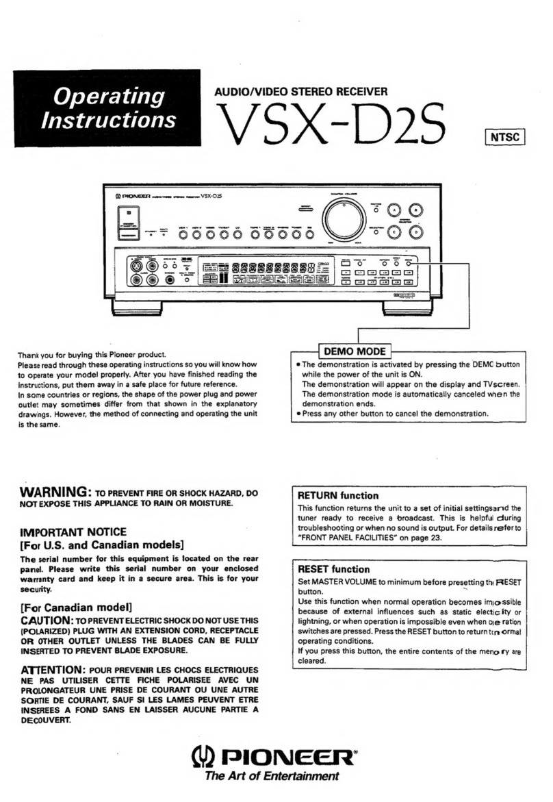
  9. Pioneer SX-5LHE User manual

Pioneer SX-5LHE User manual

(DPloNEErl'
ORDER
NO.
ARP-01
0 -O
COMPUTER
CONTROLLED
STEREO
RECEIVER
s|XI 5L
The basic
performance
of the modelSX-5L is the sameas
is a two wave-band
tuner with MW (medium
wave)and LW
servicemanual
(ARP-009)
with the exceptionof this service
applicable
to theSX-SL/HE
andSX-5L/HB.
CONTENTS
SPECIFICATIONS
PARTS
LIST
P.C.BOARDPATTERNS
SCHEMATIC
DIAGRAM
5. ADJUSTMENT
.
neclnce
AJUSTE
HE,HB
the model
SX-s.TheAM tunerof SX-5L
(longwave).
Please
referto the SX-S/KU
manual. Thisadditional
service
manual
is
1.
2.
3.
4.
2
3
8
11
14
15
16
Line
Voltage
Selection
LineVoltage
canbechangedwith the
following
steps.
1. Disconnect
theACpower
cord.
2. Remove
thetopcover.
3. Take
outthe
fusefromthe
fuse
assembly.
4. Re-istall
the
fuse
inthecorrectvoltageindication.
5. Stick
thelinevoltage
labelontherear
panel.
Description
220V label
240V label
ffs[--zzov
::--::- L240v
T1.64
MODEL
SX-sLCOMESINTHREEVERSIONS
DISTINGUISHED
ASFOLLOWS:
Type Voltage Remarks
HE 22OY and 240V (Switchable) European continent model
HB 22OY and 240V (Switchable) United Kingdom model
HEZ 22OY and 240V (Switchable) West Germany model
PIC'NEEFI ELECTFICINIC CC'FIPC'FIATIGIN 4-1, Mesuno 1-chome. Mesueo-ku. Tokyo .1
s3, JBpen
fJ.a. FlCtNllF| ILECTRCINICB CCIFIPCIFIATICIN 85 Oxfond C).rve, Moonachre, New Je.sey O7O74, U.S.A.
PlC'NllFl CLICTFICINaC aElJFlCrFEl N.V. LurEhagen-Haven g, 2O3O Anrwenp, Eletgrum
FfCtNllF| :LECITFC'NaCB ALTSTFIALIA PTY. L?O. 17e-1A4 Boundanv Fload. Elnaesrde. VicEonia 3195. Ausb.alie
rH@orc.tsar Printed
in
Japan
1.SPECIFICATIONS
Amplifier
Section
Continuous
Average
Power
0utputis 32
watts*
per
channel,min.,at8 ohmsfrom
40Hertz
to 20,000Hertzwithnomore
than
0.08%
totalharmonicdistortion.
ContinuousPower
Output at 1kHz (both channels
driven)
T.H.D.1"/o,8ohms . 40
watts
per
channel
Total HarmonicDistortion (40 Hertzto 20,000 Hertz,
I ohms,
from AUX/VIDEO)
continuousrated
power output . No morethan 0.08%
15watts
per
channel
power output. No more than 0.02%
f
ntermodulation
Distortion
(50
Hertz;7,000
Hertz
=4 :1,
8 ohms,from AUX/VIDEO)
continuous
rated
poweroutput . No morethan 0.08%
Damping
Factor
(20Hertzto 20,000Hertz,Sohmsl . . . . . . . 50
Input (Sensitivity/l
mpedance)
PHONO ....2.SmYl5Okitohms
AUX/VIDEO, TAPEPLAY .. . . 150mV/5O
kitohms
Phono
OverloadLevel
(T.H.D.
O.1%,1,000H2)
PHONO ....130mV
Output (
Level/lmpedance)
TAPE REC .15OmV12.2
kilohms
Frequency
Response
PHONO
(RIAA Equalization)
. . . .30H2to 15.000H2
r 0.3d8
AUX/VIDEO, TAPE PLAY 'tOHz
to bO,000Hz
1! 5 oa
Tone Control
BASS.. .r8dB(t0OHz)
TREBLE . rSdB
(10kHz)
Loudness
Contour (Volume control setat-40dB position)
+6dB
(1oOHz)
Humand
Noise
(lHF,
shortcircuited
A network)
PHONO ......76d8
AUX/VIDEO,TAPEPLAY ...... 96dB
Hum and Noise
(DlN, continuouspower/SOmW)
PHONO . . .76d8/66d8
AUX/VIDEO, TAPEPLAY . . .87d8/68d8
FMTuner
Section
Usable
Sensitivity.. . . Mono; 11.2dBf
(lHFl (1.OpV,
75 ohms)
Ssnsitivity
(DlN) . Mono;1.0pV/75ohms
Stereo;40rrV/75ohms
50dBQuieting
Sensitivity .Mono; 16.3dBf
(1.8pV,
75
ohms)
Stereo;37.2d8f
(19.9pV,
75ohms)
Signal-to-NoiseRatio. .
Mono;75d8 (at
85dBf
)
Stereo;70d8 (at85dBf)
Signal-to-Noise
Ratio
(DlN) .
Mono;72d8 (at
85dBf
)
Stereo;7OdB(at85dBf)
Distortion {at65dBf
)
Mono. 1O0Hz;0.15%
lkHz; O.15o/o
6kHz:O.2o/o
Stereo ...'1O0Hz;0.37o
lkHz;O.3Y"
6kHz;O.4/o
CaptureRatio. ....1.0d8
Alternate
Channel
Selectivity . . 400kHz;60d8
StereoSeparation, 1kHz;40d8
30Hzto lSkHz;35d8
Frequency
Response . . .2OHz to 15kHz
+0.5d8,-ldB
SpuriousResponseRatio ... 65dB
lmageResponseRatio .... 65dB
lFResponseRatio .....9Od8
AMSuppressionRatio ...... 55dB
Subcarrier
Product Ratio . . 40dB
SCAReiectionratio ..... 60dB
Muting Threshold. 29.3dBf (8pV)
Antenna Input . . . . . 300 ohms balanced,T5 ohms unbalanced
LWTuner
Section
Sensitivity
lHF,ferriteantenna ....450rrV/m
lHF, external
antenna . . 4OttV
Sefectivity ......27d8
Signal-to-NoiseRatio. .... 50dB
lmageResponseRatio ...40dB
lFResponseRatio .....73d8
Antenna Built-in
ferrite looostick
antenna
MW
Tuner
Section
Sensitivity
lHF,ferriteantenna ...300frV/m
lHF,externalantenna ... 15pV
Selectivity . . 27dB
Signal-to-Noise
Ratio
.
lmage
ResponseRatio
lF ResponseRatio 73dB
Antenna Built-in
ferrite looostick
antenna
Miscellaneous
PowerRequirements. ..... AC220V,50Hz
PowerConsumption . . . . . .2O0W
Dimensions ....420(W) x98(H)x31l(Dl mm
16-9/16(W)x 3-718(H)x12-1
l4(Dl in
Weight
(without
package) 5.8kg
(121b
13oz)
FurnishedParts
FMT-typeAntenna ..........1
DryBatterySUM-3"AA" ........2
StationCard .........5
Operatinglnstructions .........1
*Measured pursuant to the federal Trade Commission's Trade
Regulation rule on Power Output Claims for Amplifier.
NOTE:
Specifications and design subject to possible modification without
notice.
2.PARTS
LIST
NO?ESI
o When ordering resistors, first convert resistance values into code form asshown in
the following examples.
Ex. 1 When there are 2 effectiue digits (any digit apart from O),such as 560 ohm
and 47h ohm (tolerance
isshown by J=5%, and,
K=10% ).
560f, 56 x I0l
47ha 47 x 103 561... .. RD%PS
66tr J
473.
.... RD%PS
@A@ J
0.5{z 0R5 . . RN2H @lE6 K
la 010 .. asrP @E@]K
Ex. 2 Wen there are 3 effectiue digits (such as in high precision metal film
resistors).
5.62ha 562
x 10' 5621....RN%SRBtr,AAF
c The ii.,mark found on some component parts indicates the importance of the
safety factor of the part. Therefore, when replacing, be sure to use parts of
identical designation.
o For your Parts Stoch Control, the fast mouing items are indicated with the
marks ** and *
** GENERALLY MOVES FASTER THAN *
This classification shall be adjusted by each distibutor becauseit depends on
model number, ternperature, humidity, etc.
Contrastof MiscellaneousParts
ELECTRICAL
PARTS
Mark Symbol & De5cription
Part No,
Remarks
SX-sL/HE sx-5L/HB sx-5/KU
l!'' *
A
t\ **
A**
A**
A**
a**
A
1!,
T101 Power
transformer
Power
transformer
C101 Ceramiccapacitor
5103 Push
switch
(POWER)
FU101 Fuse
ff2.5Al25OVl
Fuse
{4A)
FU102Fuse
(T1.6A/250V)
Fuse
(64)
FU103 Fuse
(T5A/250V)
Fuse
{6,4)
FU104 Fuse
(T5A/250V)
AC
socket
(AC
OUTLETS)
ACpower
cord
Terminal
(SPEAKERS)
Terminal
(AM
STEREO
OUTI
^ll:1'
ASG.522
AEK-4O3
AEK.4O5
AEK-015
AEK.O15
AKP-026
ADG.O41
AKE.1O1
^ll:i'
ASG-522
AEK.4O3
AEK.4O5
AEK.O15
AEK-015
AKP-O44
ADG-051
AKE.101
ATT-840
ACG-017
ASG.521
AEK-1OO
niri-iog
AEK.109
AKP.O39
ADG-052
AKE-101
AKB-076
2201240V
1
20V
0.01/Ac125V
Primary
Primary
Primary
Output
Output
Output
Output
P.C.
BOARD
ASSEMBLIES
Mark Symbol & Description
Part No,
Remark
SX.5L/HE SX.5L/HB sx-5/KU
Complex assembly
Control assembly
Switch assembly
Fuse
assembly
Control assembly
A
Control assemblyB
Connector assembly
GWM.226
GWX-775
Can't besuppli6d
Can't besupplied
Can't besupplied
Can't besupplied
GWM.226
GWX-775
Can't be supplied
Can'tbe supplied
Can't besupplied
Can't besupplied
GWM.207
GWX-706
Can't besupplied
Can't besupplied
Can't besupplied
Can't besupplied
OTHERS
Mark Symbol & Description
Part No,
Remarksx-5L/HE sx-5L/HB sx-s/KU
Front
panel
assembly
Display
cover
Strainrelief
ANM.126
ANR493
AEC-337
ANM-126
ANR-493
AEC-337
ANM.O74
ANR-407
AEC-358 ACcordstopper
PACKING
AND FURNISHED
PARTS
Mark Symbol & Deccription
Part No.
Remark
sx-sL/HE sx-sL/HB sx-5/KU
Packingcase
Sidepad
T-type FM antenna
Operating instructions
(E
nglish/German/F
rench/
ltalian
)
Operatinginstructions
(
English)
Station card set
AHE-OO6
AH4-294
ADH-OO4
ARE.O21
AAN.O37
AHE.OO6
AHA-294
^?::i
AR8-461
AAN.O37
AHD.953
AH4-294
^?:::
AR8.438
AAN.O28
Complex
Assembly
(GWM-226)
CAPACITORS
Part No,
Mark Part No. Symbol & Description
Symbol & Description CEA221M1OL
CEA
221M35L
cEA221M't6L
CEA331M5OL
CEA4TOM
16L
CEA221M
8OL
CEA
47OM
8OL
cosA 511J50
cosA 431J50
coMA 302J
50
CGBR47K
5OO
coMA 103J
50
coMA 183K
50
coMA 104K
50
coMA 273K
50
coMA 333K50
coMA 473K
50
cosA 271J
50
ccDcH 220J50
ccDUJ 040c 50
ccDTH 100D50
ccDsL 060D50
ccDTH 120J50
ccDcH 020c
50
ccDcH 080D50
ccDcH 150J50
ccDcH 330J50
ccDsL 101J
50
ccDSL 221J50
ccDsL 100D
50
ccDSL 101K 500
cosA 201J
50
ccDSL 220K500
c358,C359
c327,
C410
c134
c330
c2't3
c403
c404
c136
c204
c31',t
,c312
c107
c309,c310
c344,C345
c348,C349
c350,c351
c356,C357
c406,c407
c602
c229,C230
c101,c102
c104,
c105
c106
c114,C115
c113
cl16
c112,C',!18
c117
c108,c301.c302
c125,C331,C332
c313,C314,C342,C343
c203,c225,C354,C355
c601
c352,C353
ACM-014
ACM-006
ACM-015
ACM-010
ACH-309
ACH-224
ACG-O19
CEANL
R47M
50
CEANLOlOM50
CEANL2R2M50
CEANL
lOOM
50
CEANL4TOM16
CEANL4R7M
50
CEA471M25L
CEA
R33M
sOL
CEA
R68M
sOL
CEAOR1MsOL
CEAR47M
sOL
CEAOlOM5OL
CEA2R2MsOL
CEA4R7MsOL
CEAlOOM
sOL
CEA3B3M
5OL
CEA22OM25L
CEA47OM25L
CEA47OMsOL
CEA1O1MlOL
CEANL
1RsM50
TC101,
TC102
Ceramictrimmer
TCl03 Ceramictrimmer
TC201,TC202
Ceramic
trimmer
TC60'1
, TC602
Film trimmer
c303,c304,c315,
C316
Electrolytic
(2.2/50V
NPI
c411,C414
Electrolytic
(8000/42V)
c412,C415
Ceramic
(0.01/AC150V)
c1
50
c137,C138
c321,
C322,C328,C329
c340,
c341
c307,c308
c135
c41
I
c408
c609
c233
c147
,C148,C209
c122
cl27
c206
c149, C223,C362,C363,C401,
c413,C604,C607
c212
c360,c361
c333,C405,C409
c402
c132
c232
Part No. Symbol
& Description SEMICONDUCTORS
Mark Part
No,
CKDYB472K50
ccDSL2t1J50
CKDYX183M
25
CKDYB
561
K 50
CKDYB182K50
CKDYB222K50
CKDYB392K
50
CKDYB471
K50
ccDTH 121J50
ccDSL 560J50
CKDYF223250
CKDYB1O2K
50
CKDYB1O3K
50
ccDsL 470J
50
CKDYF1032
50
CKDYF
473250
CKDYX
1O4M25
RESISTORS
c346,C347
c323,C324
c139,
C140
c141,
C142
c145,C146
c143, C144, C2',t1, C334, C335
c317,C318
c305,c306
c605
c901,c902
c215,
C214,C221.C222
c214,C219
c111,C227
c319,C320,C336-C339
cl03, c109. c110, c119, c120,
c153, C201. C202, C207, C211,
c224, C226. C228, C231. C234,
c325,C326,C608
c121, C123, C124, C126, C128,
c129, C130,C131,
C133,C151,
c205, c210, c220, c364, C365,
c603,c606
c216
Symbol& Doscription
NOTE:lirhen ordering resisfons, conuert the resistance ualue
into code form, and.then rewrite the part no. as before,
Mark Part
No. Symbol& Description
** LA1247
** M54922P
r * PA3001-A
** HA1156W-P
r* PA4008
(PA0001)
** JC501
(25C2603/A/)
** 2SC1919
(2SC1845)
r * 2sc2362
1.2.SC2240l
(2SC1775A)
** 2SC1384
(2SD438)
** 2SC1845
{?.SC2240l
** 2SC535
** 2SC461
(2SC71
0)
* * 2SD880
(25D31
3)
** 2SC2603/A/
** 2SK34
* * 2SA850-C*
(2SA850-D*)
(258560-D*l
(25B56GE*)
** 2SC1735-C*
(2SC1735-D*)
(25D438-D*)
(25D438-E*)
*r 2sA798
** 2SA1115/A/
** 2547265
(2SA9921
** 2546844
(25Bs60)
* * JA101
(2sA1115/A/)
*r 2sK168
(2SK61-GR)
** 258686-0*
(258686-R*)
* * 2SD716-0*
(25D716-R
*)
o201
Q207
o107
0108
0329
o109, 0203-0205,
0405, o313, 0314,
0609
0202,0301,0302
0309,0310
o401
0307,0308
o102
0104,0105
0402,0403
0315-O318
0601,0603,0610
a321,4322
0.208-4212,
0605, 0606,
*
t
*
ACP-079
ACT-O23
ACT-140
c92-051
ACN-114
ACN-133
ACN-134
RNZoPODOIDF
RD%PSF
trtrtrJ
RD%PS
trtrtrJ
RD1/4PM
trtrtrJNL
RD1/4PMF
trtrtrJ
RDl/8PM
trtrtrJ
RD74VM
trtrtrJ
RD74PM
N!trJ
VR101 Semi-fixed(Sk-B)
VR302 Variable(BALANCE)
VR3O3,
VR304
Variable
{TREBLE,BASS)
VR3O5,VR306
Semi-fixed
(4.7k-B)
R419,
R420
Wire
wound
(0.47l5W+O.47l5W)
R505 Wire
woundl47l1OV{l
R511 Wire
wound
(120/10W)
R136
R389,R41
5-R 418,
R421
-R428
R512,R515
R305-R308
R208,R406-R408,
R410,
R503
R251-R254
R613.
R614
R101-R135,
R137-R150,
R201_
R207, R209-R228, R230-R250,
R255, R256, R301-R304, R309-
R329, R332-R353, R360-R388,
R390-R405, R411-R414, R501,
R502, R504, R506-R510, R513,
R514, R601-R612. R615-R621,
R701,
R702
A
A
A
* hfe of 0321-0.324 should havethe same
value.
o,32s,0324
0305,
0306
o31
1
,
O312,
O31
9,
0320
0110,
01
11,
0303,0304
0404
0106, 0206, 0213-0215,
0607,
0608
0101,
0103.0602,0604
0325.0326
0327,0328
A
* hfeof 0325-0328 shouldhave
thesamevalue.
5
Mark Part No. Symbol& Description OTHERS
Mark PanNo. Symbol
& Description
-
-
r-
wz-100
(KZL100l
(MZ-1001
wz-o48
wz-l10
(Mz-110)
(KZL110)
KZL056
KZL140
w2-290
MZ-150
(wz-150)
KZLO72
w2-046
luz-o47l.
15247'l
GP-25D
(30D21
10E2
(srB01-02)
1S1
555
(1s2076)
(
1S2473)
TH103-2
KV1320A-3
KV1225-Y
D602
D206
D205
D409
D301,D403
D401
D416
D402
D306-D309
D407, D408
D412-D415
D404.
D405
D102, D104..
D105, D203, D204.
D207-D209, D302-D305, D310-
D316,D410,
D411,
D417,D603-
D606
Th301,
Th302
D101
D201
** ASG-300
* * ASG-309
r ASS-016
* ATF-125
AKA.O18
AKB-077
AKB-079
AEC-818
5101 4ganged
push
switch
S104 Push
switch
(MW/LW)
x2o2 crystalresonator
X2O1 Ceramic
resonator
Terminal
(ANTENNA)
Terminal
{PLAY}
Terminal
(PHONO,
AUX/VIDEO,
REC}
Mica
wafer
A*
a*
A*
* KV1320A-3
consists
of threetwin vari-capdiodes
with theindenti-
calcharacteristics.
* KV1225-Y consists
of three vari-cap
diodes
with the indentical
characteristics,
COILS,
FILTERS
Mark Part
No, Symbol& Dsscription
ABA-258 Screw
PBZ30P06OFMC Screw3X6
VBZ30P060FMC Screw3X6
ControlAssembly
(GWX-775)
CAPACITORS
Mark Part
No, Symbol & Description
CKDYB
331K
50
CKDYB1O2K
50
CEA1O1M
25L
CKDYF1032
50
CEA47OM
25L
RESISTORS
NOTE:llhen ordering resistors, conuert the resistance value
into code form, and then rewrite the part no. as before.
Mark Part No, Symbol& Description
LBDT4PMF
trCtrJ
RD%PM
Ntr'J
RDl/8PM
NtrtrJ
*
*
*
*
*
*
*
t
c3
c4
c5
c7
c8
SEMICONDUCTORS
Part No,
R52
R9-R22,R34,R41,R44
R1-R8, R23-R32,
R35.
R42,
R43,
R45,
R46,
R53
Symbol& Description
ATC-I12
ATC-131
ATC-I15
ATH.O49
ATX-025
ATB.067
ATD.O13
ATE-039
ATE.O52
ATB.069
ATF-126
ATF.121
F101,
F102
Ll01
L102
Ll03
L104
L202
L203
L601
T101
r102
T201
FM ANT. coil
FM RF coil
FM OSC.
coil
RF chokecoil
Bar-antenna
assembly
AM OSC.coil
LW OSC.
coil
FM lF transformer
FM DET. transformer
AM lF coil
FM ceramicfilter
AM ceramicfilter
* * PD6O(MA
** TD63O1AP
** M74LS42P
** TC4049BP
** 2SC2603/A/
(JC501)
** 2SA1115/A/
(JA101)
* 2-1K261
* 151555
(
1S2076)
(
152473)
* AEL-378
* AEL-365
* AEL-351
o5
02
o6
o3
o1
013,
014
D1-D10,
Dl5
D11,D103
D32 LED
numeric
display
D19-D25,
D17,O29,
D30.D101
LED
(Red)
D26-D28 LED
(Green)
F201
-
OTHERS
Mark Part No. Symbol & Description
* * ASG-177
r ASS-020 S1-S13 Tact
switch
Xl Ceramicresonator
PTZ26P080FMC Screw2.6X I
Control
Assembly
A forSX-SL/HE,HB
RESISTORS
Mark Part No. Symbol
& Description
RDz4PM
.trlJ R33,8101-R103
RD1/8PM
trtrT]J R39,R4O
SEMICONDUCTORS
Mark Part
No. Symbol& Description
2SC2603lAl
(JC501)
2SA1115/A/
(JA101)
010-o12
01
01,01
02
ControlAssembly
Bfor SX-SL/HE,
HB
CAPACITORS
Mark Part
No. Symbol & D$cription
cEA010M50L C1,C2
CKDYF1032
50 C6
RESISTORS
NOTE:llhen ordering resistors, conuert the resistance ualue
into code form, and then rewrite the part no. as before.
Mark Part
No. Symbol
& Description
RDY4PM
DtrtrJ R50,
R51,R56,R58
RD1/8PM
trtr-J R36-R38, R47-R49, R54, R55,
R57
SEMICONDUCTORS
Mark Part No. Symbol & Description
** TC4069UBP
** 2SC2603/A/
(JC501)
* sz-o27
* 151555
{
1
S2076}
(152473)
04
08,
09,015,
016
D31
D12,D13,
D16,D33
Connector
Assembly
forSX-SL/HE,
HB
Mark Part
No. Symbol
& Descliption
* 10E2
* 2-1K261 D18
0102
{
3
2
B
3.P.C.BOARDPATTERNS
Ttol Tc202
LIO1 L203
fu';'t.""Ii"''&
1,'*,t::t'f,,'-f
i
H
t.,$ffi{fii,:'iW.**i;1,,*
ffi
tL
id;},l,i,i:flfi
ffiffi'-'Tfll,$i
li;ir:i-
fi,i,,,t
t**ftffi,
l*, l
rr*,rIriT,
s I
16;t,,"l;,'*i''-'
ll':
li
rn"'i
' '*il1],,i.-li.pjt",tti,l,+.
tfti
jii[*j"I
*'t
d:j,
r li#r,,,,',T*rtr
sf-
:klt -"1yt1,,H;ffig--."-:
-"''l'
f-lii l''** t.ilir
'nt---"za{ ft I o3oe,31o2sce352
.l l. ? ^ Q311,312,319,320
.l ^ l. l-i ll"tit e2o3-205,208-2r2 03r?*3r4 0306-309 0302-305 zsa1r5rar
.l *- l. Rfqol
[ - Jc5o1 1s15s5 wz
-046 1s15s5 Q313,314
Jc501
"l S *1. ?'u^J
E n,,, e213,214
JAlol o3l5-318 2Sc2603rA/
ol n l. I R{'r' - 0321,322 2sA850
.l'g l.{.-J3
:l S |11FL,.,,:;,i,T&--'1ilK0-e3.45- 1" 1^.". lo,,
"l c; l..dorosJg{_..cotr \_eq 1 ftlorzet ^on, ? f tc$ ?t{1
;l :,,1;1i.;-"i3'{^illlllrlft)\ **.I "-rdl. I n*oczts*r.z
-4r- e r_ t\it^ tvr^ "-'tCt-
@*n@ @-"^ o @
h\,,. ;l 'q'-"-t*l
f:*++ iQ lr*l[q*rl'
t"o'ot
9-""3'9""9 t"^'n e6o1
"''9 (**J - xrffr,}.l#,i''l
jS6dlrthl
,.r,0,
" I Lzo2 ?c e6o2.
, T \_-y o J Jzzx l .;zzor""'
''"' r--------;--"t I t R,o? 0605,l
o \:--z ? a r1la t ^, 0"" ^ ^^-^^^ tfr:-;;-t , 1 !^sgq Q6o5,l
Dzor | 3A "^ l/*tl 1- l.-, I c{dB 6 } | * +".", o310Konroa
Rro3o
oRrorRso, 0607,.
,,1#,,i,,{*.i.:l.4{-lr,Hi#itl,:-olm*|t'.,',-ij'9-|-*i#ii?Tt,r:...
o"l'l*
-r'':ut.ifq'lmi'K+',,1"""ri..T,*",tj
+{*+j-l
i'*''?fu;'"';
';*l
Iff,j,,,,.,,,
1:
.1.i-',
..-:tJ
li':ruTiF+ffirrr'IT:n:
IIrt"
It,r*ii'
.*hi:i
:GJu
,',,**:#tll:[|:
ili$ll
*'1;-d{3ilI#Ir,ryiffiff:-ffi*#1',-lffir-4;llifli,n-'o6o7,'
p
T,nil
.*
1**H#
I
E+,f;Trml+sreru
iffi;{:i'
dJ"|i
:
;'H,,,
ti,,-.d['t.ffi-i
$,{
I
lE
*ti
f-fffi$fifr*;,#;f$ffip:
fimlffiffiffid;ffiffi$fi
ffi
'$ffi
,,,/
i
i
r'di'
Y1i:'
iil,t*,r.m:#t_t
.Bifi
+_{,
ffi '#J
#t
ffi;-
r*lll,l4W
tu'\fJlrlqff
ffiff4ffi61ffipffi*r,.iT
.*,#l
g,q*ffi;jil
1Ilbll
i$'"$l
IilLffil$iffimd,*p
,{q'1iilffil
l1ilrui:[Ji*i4T
:lhtJ
'[]';-
q;I;l'l
'td:
,fif#l
ffiru'fi
ffiffil,t
I
l1,t'u
"ry
V'-+
i-.;{;'1,il
i,:Fi,,
t;,1,1
t
]
I,i1jlj
]
ti
l**
l"o'* | l^;,." T ^.:"--...^. \---F Do4,ro5rslb5s qroe Jc5or 12R D3lo,rlr,3r5,5r6
LqXf I'n- I u'vo
rarur e1ro,r1
2sAz26s ts155s
""'l'l,it6 | ozor'zoo
zoz-zos
---lt1"t tvl """ t a3o9,3!o 2sc2352
flilli
ffiF-
lru:{l,
sh#
H**fij#IiiFJifffij
#- tryfuffilffiffr*t#$l
r,l
I
I
l;i
r;
l+f#'ffiLfimi-};ffitrpTflb$
tjil
fffr*
il .ouo"rr.r.o'rl,rr
r'orf'
ffi ;
;
pil,
-
[
L,],
r,ilr*thffi**
'$';#'-#f,flJ
i""fi,f;rl,e
f 102
Complex
Assembly
(GWM-226)
r
rl|'l,th
ill;:h
rlllllnr
Q2O8Q2r4 Q1O4 QlO3 Q211
QlO2 qlo5 O2O4Q213
QlOl Q2o9 Q2O7Q2lo Q2o3 Q2O5
Q6Io 0212 Q1o5 Q6o2 Q6o4 Q6ol
Q3O6 Q2O2 Q326 A3OA
Q3tO OIOA Q312Q3la
Qrlo Qlll Qtoo
Q6O7 Q6OA Q6O6
I
I
I
I
os2Q3rOO3O4 Q329 Q32j a3l7 Q3O7
e3r4 Q313
Q3o9 Q325
o32? 0'3010303 A3t7
QioT 020r
Q6O5 Q6O5
t-1
z
Q3r6 Q32a Q32O
Q324
Q6O9
3
-l"
65
4
e,
/rN Q60r,603,610
2SK34
Q602,604 25K168
Q605,606,609
JCSOr
0607,606 JArOl
!il'
I U303
{2.2/50 Q3Ol,3O22SCt9t9
Q3olc.inr:r Q303,3O4
?5A7265
ti\ I J550e+
caoT
XJl{ f ++1/tE
iz.Jlgryi{!3!'
ii'iqrol-\{ a ..
I rrylt1J!:r'1'
u',1
{",1'
/r.lI t I
isol l18x^{mPl i {noo
- R:zsl
IR!21l? ?100K
n,..r3wl f *? t_l J
iid;f.lg3!./tl*,
o ,*' I il,:'l
-,1ii'i'i'rrffl
e'.-y'**?1-ti.lf{*-
|
I
lirurltt'hlll
' ?i"i3'
"':i'
'" I
r,
lltld,i
"l11il
I+#'-t
t*.r,*,1
[
I
hi''ffi't$f
1
;,'1.-$fii
l,lj
fl
'";;;
lo3"".TtfJ
lui'lll' I I ttil" I I I T I I o6 o5
llllfiRrdrB:"r/ti I I r r ,I | | | I i**to*'
ffJ
t4'lt* r 0,0",,'u,o'o'
J I
,,,00.,0,,,.,u.,"
)6'25JA'|o
i I "/u*,ri1$
Ii"
t'-'i"i-'
*:'l;;:-'ll
lllll;"rdiili lo" I I t \ o | | I I I I*:lT'*' Tf
it I
lJtw"'"
/ 0,0",,,u
,0,0,
i I {n*r)h-'I {.,.{_"*,.,L,.
Jt'
I o*.1
1
lll"r?i- ,2i/,l, \i l"--l-*l^-1"'" 0491..499r1
)3100.,0.311315,3,6 /";ql I t iisltil:i,,,, J
oo,rJ_o,oiur_rlo
''io"
zsc2t6z e305,306
zsa7s8 e402,403
zso'so *'l t J ] tTr,o4
rbA
- tB ,
.tXA* m*
ne,32o s3o7,
3os 2sc1845 Q4o4 2sA684A flii*rf t l-----F-J-----l o | |
" I il i ** 1or -*p::t. c*l
zscztoz e3o5,ro6 zsl7s8 e402,403
2soe8o lTt i I -ru,or r5A
- '-o r ln00b2 opqrT
ne,32o s3o7,
3os 2sc1845 Q4o4 2sA684A flii*rf t l-----F-J-----l o | |
2sAfi3rAr Q4O5 Jcso.t I I I t_ .<l , t1fi.l | ? 6 4
Jc5or Q32r,324
2sc't735 e A I l;l I l- o
2sc26o3ra, e325,326
2s8686 *crse| .El l+f3ji 3e
zsraso. Q327,us 2sDz16 ^_ {0.033
I f-**t'Hl3f---*-f .fE | |
(u2w)
27
t I oo € It 20
,
A" l --iuruy--L"*.*1
r.ilfi;
l*+:*^#.;f*-:4;ffi,,,l,*,i .r r---^^
li.. ,l,rfi,J
id:",-*u.r#*:
gt-#[t;1
t T'Ht'?tri&l'i"'
'5 5}t"-i-*]:".]'??l'k'l
.tru^'^sfff
{m
f*iEt,lj"qlj$t
llli,r'f,*ili+ri-_-=5*+l
ifj*+Te
1."
' , 6
'o..;JJJJ;b"..',$'t--:l,;LJl%,{,,.*-,.,,,1,h,o*,,-i$,,drWo
"m,fud
Iif+'J,H,qt'di'iI+1-I]
l*-"'"'
-'i'i:l
I
_|ul''[,td,,tj_.%
$ln!l'ilnH#flmjl''WWrt
,,"
ffid*h*r.,
r#,
-iJ{#,;
+,il#l,FH*i;,[=*
l
i ;mffii
Co
ti
li
I
Co
(T
t;--
I to
tL
l"
I
I
I
|
03,
IJ
IT
lQ8,s
LJ
Control
Assembly
(GWX-775) ,iTI
1"@lr-
I I lfcfiriiirurorI
H-Tirryi.lr;+=
r
{?lt*l
t+++t\zn//(
rllll llllt t// I
++\L_r'
] )_/ |
llpo+ l
6 0j,;" (6) (5) I
Ll'""o''r@i o'.rff \
;o3/a/ < r
15/
a/ .T-T- J
ll.sl I lffi
lli;]1lJji%
l6do
to' L.6l
tv<
I trape
t
*,F* *ffi-*, l'
*+sl!- --|-!:i1l-tzxl
t1 -
oxll li\
JJ l Inl?l
Y Y 6 o o(
rt-tl
|41 |
9 l+o
o{l " I l
f'T,,
LI*F fftJ
i
I 1 r-7^
t?9,*
' I tl;l-1 or zsc26o3t
rzor6 ll"-Jlors.r+
, Ll
t'.
lJ ? 2sA1r15/
JD'or o o I
T
isr555 I
I Gm=+J ?
0,, |id1* I
rsr5ss
- lot
I
D8
t
T
6
5I
Q32r O3r7 Q3O7 Q2t5 Q3fi Q4O4 Q4Ot Q3l9 q323 Q315
1Q3o9 q325 e327 0206
I Q303 Q3r7 Q305
ln
|1l
l'a
I
I
I
8
7
6iT
:
rdt;il$.r
,
,i:fr
r'.-11
,.
f
,,,1
,ll&r,
rt,ilt,
"fr
'1'
{'*
r't-.
t -
I-+.
irn9-.
,*I
or,T
l.l
C
Control
AssemblY
A
Trr*@94
Lffiffilll
D
I
8
7
Connector
Assembly
Fuse
Assembly
Control
Assembly
B
3
I
l2
DIAGRAM
I
4.SCHEMATIC
A
B
C
tri;itt_ -.
IPLAY/|N
r cx
| *"or..'
@*arr,n * a"
I
I
L *cr*r " c"
D
13
2l_
ozr.,oroo' - - -*
Q6O5,66 JC5O1
2SCl6a5
q!o5! !06
O3Os-324 POWEF
AMP
6
54
2SO6AO
fl.."...
' I ta;;1;;',
I
I
J
olo7, loa
2SClaaa
o!o3, !06
2SA79a
ll05.32B PoWER
^tP
0207,2OA,209
r$aa5
*i u lfl---=1Y=
I
i
'-':-'
.)
6
54
--..-*_-----lJ
HEADPHONES
JACK Atr't
[---l
.r?r ce. "ilo!.' :iddD .r?'
1e NMte' o'<" ai / / 7 'f-h l-l rt
il! I l-l ,t-t, . lat .tt
AEL-376 ?
I
7
NOTE:
The indicated semiconductors are repre*ntatiue ones
only, Other alternatiue semiconductorc may be used,
and
are lbted in the parts list.
s3
s5
sr2
CONTRoL As5'yA(l/3)
t-;;;;;'t
D3J
SZ-O27
L
L-::
s ror - | TAPE/aDAPT ot 9f!
S IOI 2 TUiITG SIATIOI SCA{ - MANUAL
5 'Or 3 MOrc/MUIE OFF ST€RaO/ON - rcNO/OFF
5 ro 4 LOSTESS O! - OFF
3 03 POWER o* - ry
5 IO4 BANO SELECTOR
(W/LW) LW _ M9
'/3r, .5* rorennce 0d*s orhs.w,s noid
k kr M Mlr,1Fr 'r%.rG) 2q 1K) .to%_{Mt ,20%roeranc.
Inn
cded'n cana.ry 1!Fr!o re ivr udes orherwse
nored
p pF
vors 6 50v rxceor
3 VOLIAGE CURRENT
LI sr, *.e" 30w+ 30w B,:ou,DU,1r!B?)
I-l Dcvobelvrdoo nDUrsqnil
V: ue n 1 I 3 ocv. rqe ar ,il.d Nw.(
fte ; -a,( io."d on eme
ON 9!E
oil Slt
ON 9E
oN - 9!i
dq
ON 9I!
ON 9EE
otr 9!!
ONffi
oN e!!
oN s-i-t
ON 9I!
I CONTROL
A..'y A
) t2/!) -l
L-_-_
CONTECIOR
ar.
y t2/3t
r;--'1-
-
;r
o?5
EL-!51
r-----
to15.16
lasc26!/A/
!
ar5
l,:y[11f,
I lrAUTotu-0N'
'-l
.---i I r o'
CoNTROL
A33
y A
|
3/3)
t..
zsczeoltat I
uq,ro2 !
asA11r5/A/ :
aia.ii.ir.0, l
__._g!-_oN) |
(1/3)
f
jL_ ".iK:l"-
j
, F+J= rv1g:_ls-.e1+ar'" .o"\!, rLl, i
i\Di' I h$zo il.t,.|.., I
_t I
87,i9t25 l€L-!a3 O27,2l AEL-lSt ;
CdTROL
I
8
7
lsl
545
t
;l -"i
r.]"ii
'I l"i
-t,i
SWITCHING(POWER
OFF'ONI
t
ta/3)
S.ADJUSTMENT
LongWave
Tuner Section
o Connect the AM signalgenerator (AM SG) to the AM ANTENNA terminal through a 10kA resistor.
o Setthe AM (FUNCTION) switch to the ON position and AM BAND switch to the LW position.
(*3) T\me the AM SGto the SX-5L
(*4) Slidethe bar-antenna
LW coil alongthe core.
MW
coil LWcoil
€lc) E)
-______-
Step
AM SG
(400H2, 30% modulation) sx-5L
Frequency
display Adjustment
point Adiustmentprocedure
Frequency Level
1No signal 155kHz L601 2.2V DC between
terminalno. 36 andground.
2No signal 281kHz TC601 25VDCbetweenterminal
no.36
and
ground.
3Repeat
steps1and2 untilboth specifications
arecorrect.
4164kHz
(*3) 40dB 1
64kHz L202l*41 AdiustuntilDCvoltage
betweenO201
(lC)
pin16
and
ground
ismaximum,
5254kHz
(*3) 40dB 254kHz TC602
oRepeat
steps4 and 5 until maximum sensitivityis
attained,
-
-
I
-
REGLAGE
SectionTunerOndes
Grandes
o Raccorder le g6n6rateurde signaux AM (AM SG) sur la borne d'antenne AM (AM ANTENNA) par
l'interm6diaire d'un r6sisteur
de 10KO.
o R6gler le commulateur AM (FUNCTION) sur la position ON et le commutateur AM BAND sur la
position LW.
(*3) Accorder le g6n6rateur
designaux
AM SGsurSX-5L.
(*4) Faireglisser
la bobine deI'antennei tigele long deI'Ame.
BobineMW BobineLW
tr?
rc601El
C=
ff*t-"*tumr@4
6@@
iF€
rlE--11
o201
Phase AM SG
(400H2, 30% modulationl Affichage de
f16quence
sx-5L Point do
169lage M6thod€ de r6glage
Fr6quonc€ | Niveau
1Pas
de signal 1
55kHz L601 22V CCentre
la
borneno 36
etla
bornede
terre.
2Pas
designal 281kHz TC601 25V CC
entrelab
orn" no36et la
bornedeterre.
3R6pdter les
phases
1 et 2 afin d'obtenir les
deux caractdristiques
correctes.
4164kHz
(*3) | 40dB 164kHz L202l*41 Rdgler
afin d'obtenir la
tensionCCmaximum entrelabroche
16 0201 (Cl) et laterre.
5254kHz
(*31 | 40dB 254kHz TC602
6Repdterles
phasas
4 et 5 afin d'obtenir la
sensibilitdmasimum.
-15
AJUSTE
Secci6n
delSintonizador deOnda Larga
o Conectar el generadorde seflales
de AM (AM SG) al terminal AM ANTENNA travr6s
de un resistor
del0Kohmios.
o Poner el selector de funci6n de AM en la posici6n ON y el de AM BAND en a la posici6n de LW.
(*3) Sintonizar
elAM SGconel SX-5L.
(*4) Deslizar
la bobina de LW de la antena
debarrapor el nircleo.
Bobina
deMW BobinadeLW
Paso AM SG
(400H2, 3O%
modulaci6nl Frecuencr-
motrodel
sx-5L
Puntode
ajuste Procedimientos ds aiusts
Frecuencia I Nivel
1Sin seffal 1
55kHz L601 2pV CCentre
elterminal
no.36y masa.
2Sin seffal 281kHz TC601 25VCC
entreelterminalno.
36
y masa,
3Repetirlos
pasos
1y 2 hasta
que
ambas
especificaciones
seancorrectas.
4164kHz
(*3) | 40dB
.l 164kHz L202l*41 Adjustarhasta
que
la
tensi6ndeCC
entre
laclavila16de0201
5254kHz
(*3) | aOae 254kHz TC602 (lC)
y tierra
sea
lam6sima,
6Repetirlos
pasos
4 y 5 hastalogarselamixima sensibilidad.
l,\jq

This manual suits for next models

1

Other Pioneer Stereo Receiver manuals

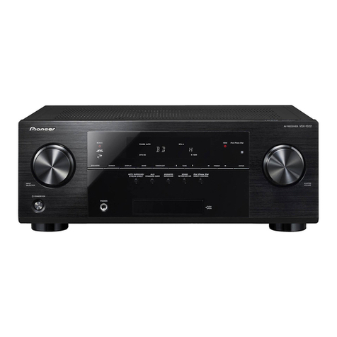
Pioneer DMH-2770NEX User manual

Pioneer

Pioneer DMH-2770NEX User manual

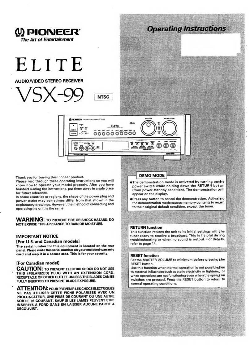
Pioneer MVH-A200VBT User manual

Pioneer

Pioneer MVH-A200VBT User manual

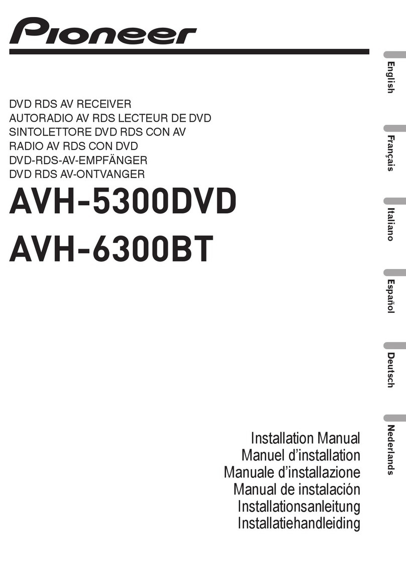
Pioneer AVH-3500DVD User manual

Pioneer

Pioneer AVH-3500DVD User manual

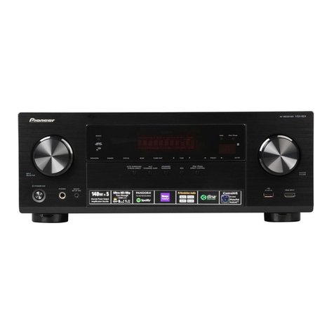
Pioneer AVH-4400BT User manual

Pioneer

Pioneer AVH-4400BT User manual

Pioneer SC-LX701 Installation guide

Pioneer

Pioneer SC-LX701 Installation guide

Pioneer SX-450 User manual

Pioneer

Pioneer SX-450 User manual

Pioneer VSX-815-K User manual

Pioneer

Pioneer VSX-815-K User manual

Pioneer Elite VSX-24TX User manual

Pioneer

Pioneer Elite VSX-24TX User manual

Pioneer XR-J1500C User manual

Pioneer

Pioneer XR-J1500C User manual

Pioneer AVH-175DVD User manual

Pioneer

Pioneer AVH-175DVD User manual

Pioneer QX-747A F User manual

Pioneer

Pioneer QX-747A F User manual

Pioneer SX-1280 User manual

Pioneer

Pioneer SX-1280 User manual

Pioneer VSX-D466S User manual

Pioneer

Pioneer VSX-D466S User manual

Pioneer VSX-534 User manual

Pioneer

Pioneer VSX-534 User manual

Pioneer AVH-W4400NEX Installation manual

Pioneer

Pioneer AVH-W4400NEX Installation manual

Pioneer VSX-834 Manual

Pioneer

Pioneer VSX-834 Manual

Pioneer Elite VSX-LX102 Installation guide

Pioneer

Pioneer Elite VSX-LX102 Installation guide

Pioneer VSX-C100 User manual

Pioneer

Pioneer VSX-C100 User manual

Pioneer DMH-WT3800NEX User manual

Pioneer

Pioneer DMH-WT3800NEX User manual

Pioneer AVH-A315BT User manual

Pioneer

Pioneer AVH-A315BT User manual

Pioneer AVH-1550NEX User manual

Pioneer

Pioneer AVH-1550NEX User manual

Pioneer AVH-A200BT User manual

Pioneer

Pioneer AVH-A200BT User manual

Pioneer DMH-ZF8550BT User manual

Pioneer

Pioneer DMH-ZF8550BT User manual

Pioneer AVH-Z7050TV User manual

Pioneer

Pioneer AVH-Z7050TV User manual

Popular Stereo Receiver manuals by other brands

McIntosh MAC1500 - SERVICE  1 Service manual

McIntosh

McIntosh MAC1500 - SERVICE 1 Service manual

Panasonic HDMI SA-XR70E Service manual

Panasonic

Panasonic HDMI SA-XR70E Service manual

Sansui 890 Service manual

Sansui

Sansui 890 Service manual

Yamaha Aventage RX-A2A user guide

Yamaha

Yamaha Aventage RX-A2A user guide

Sony ST-RDE597 Easy setup guide

Sony

Sony ST-RDE597 Easy setup guide

Sony STR-GX69ES operating instructions

Sony

Sony STR-GX69ES operating instructions

Technics SA-GX230 Service manual

Technics

Technics SA-GX230 Service manual

Sony XAV-AX5000 Service manual

Sony

Sony XAV-AX5000 Service manual

Naxa NPB-429 quick start guide

Naxa

Naxa NPB-429 quick start guide

RCA RP3753 user manual

RCA

RCA RP3753 user manual

Toshiba XB-1507 owner's manual

Toshiba

Toshiba XB-1507 owner's manual

Yamaha RX-460 owner's manual

Yamaha

Yamaha RX-460 owner's manual

Denon AVR-3312CI Specifications

Denon

Denon AVR-3312CI Specifications

NAD T763 owner's manual

NAD

NAD T763 owner's manual

Denon AVR-687 Specifications

Denon

Denon AVR-687 Specifications

Marantz SR6004 Guía del usuario

Marantz

Marantz SR6004 Guía del usuario

Bose Wave Music System IV owner's guide

Bose

Bose Wave Music System IV owner's guide

Integra DTR-8.4 instruction manual

Integra

Integra DTR-8.4 instruction manual

manuals.online logo
manuals.online logoBrands
  • About & Mission
  • Contact us
  • Privacy Policy
  • Terms and Conditions

Copyright 2025 Manuals.Online. All Rights Reserved.