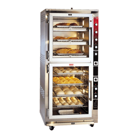
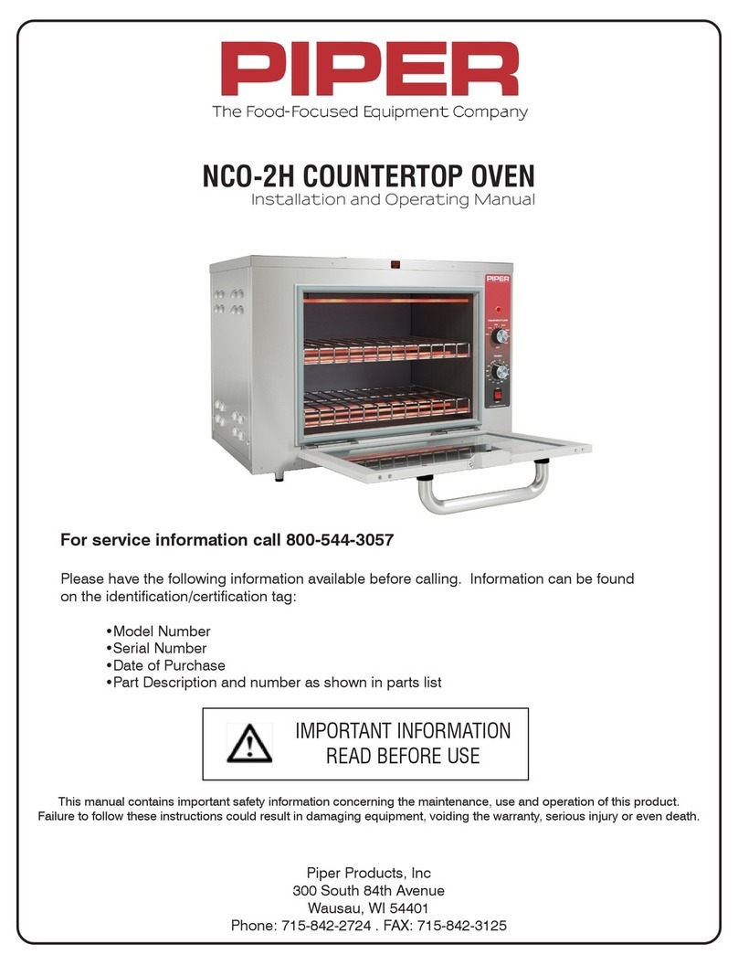
Piper DOPB-G User manual

DOPB-G OVEN/PROOFER
Installation and Operating Manual
For service information call 800-544-3057
Please have the following information available
before calling. Information can be found on the
identification/certification tag:
•Model Number
•Serial Number
•Date of Purchase
•Part Description and number as shown in parts list
IMPORTANT INFORMATION
READ BEFORE USE
Piper Products, Inc
300 South 84th Avenue
Wausau, WI 54401
Phone: 715-842-2724 . FAX: 715-842-3125
This manual contains important safety information concerning the maintenance, use and operation of this product.
Failure to follow these instructions could result in damaging equipment, voiding the warranty, serious injury or even death.

WARNING, TO REDUCE THE RISK OF FIRE OR ELECTRIC SHOCK,
DO NOT REMOVE COVER (OR BACK)
NO USER-SERVICEABLE PARTS INSIDE
REPAIR SHOULD ONLY BE DONE BY AUTHORIZED SERVICE PERSONNEL ONLY
WARNING
RISK OF FIRE OR ELECTRIC SHOCK
DO NOT OPEN !
!
The lightning flash with arrowhead symbol, within an equilateral triangle, is intended to
alert the user to the presence of uninsulated “dangerous voltage” within the product’s
enclosure that may be of sufficient magnitude to constitute a risk of fire or electric shock to
persons.
The exclamation point with an equilateral triangle is intended to alert the user to the
presence of important operating and maintenance (servicing) instructions in the literature
accompanying the appliance.

TABLE OF CONTENTS
INTRODUCTION
FREIGHT DAMAGE CLAIMS
SAFETY PRECAUTIONS
UNPACKING YOUR EQUIPMENT
ASSEMBLY INSTRUCTIONS OVEN AND PROOFER
ELECTRICAL CONNECTION
PLUMBING INFORMATION
OPERATING INSTRUCTIONS
MAINTENANCE
GENERAL CLEANING
TROUBLESHOOTING GUIDE - OVEN
TROUBLESHOOTING GUIDE - PROOFER
TROUBLESHOOTING GUIDE - AUTOMATIC STEAM AND HUMIDITY SYSTEMS
DIMENSIONS AND CAPACITIES
PARTS BREAKDOWN - FRONT VIEW
PARTS BREAKDOWN - SIDE VIEW
PARTS BREAKDOWN - PROOFER
PARTS BREAKDOWN - AUTOMATIC STEAM AND HUMIDITY SYSTEMS
WIRING DIAGRAM - DOPB-G
WIRING DIAGRAM - DOPB-G-SH
DOPB PHASE CONVERSION
WARRANTY
2
2
3
3
4
5
6
7
9
10
11
12
13
14
15
16
17
18
19
20
21
22
Model #
Serial #
Date of Manufacture
Purchased From:
1

INTRODUCTION
Congratulations! You have just purchased one of the finest pieces of equipment on the market today. Be-
fore installing or operating your new Piper equipment, you should read through this manual. This manual
should be retained for further reference as it contains installation and operating instructions, service tips,
part lists and warranty information.
For your safety, read and follow all cautions and warnings.
FREIGHT DAMAGE CLAIMS
Your Piper equipment was carefully inspected and packed before leaving our factory. The transportation
company assumes full responsibility for safe delivery of this equipment. Piper Products cannot assume
responsibilities for damage or loss incurred in transit. Visible damage or loss should be noted on the
freight bill and signed by the person making the delivery.
A freight claim should be filed immediately with the transportation company. If damage is unnoticed or
concealed until equipment is unpacked, notify the transportation company immediately and tell them you
want to file a concealed damage claim. This must be done within five (5) days after delivery was made. Be
sure to retain all packing material and cartons.
WARNING
Installation of this equipment should be done only by persons qualified or licensed to install
electrical equipment. All electrical and plumbing must meet local, state, and federal codes.
Plumbing installation must be performed by a qualified plumber.
Adjustments and service work should be performed only by a qualified service technician. Service
is available through Authorized Piper Parts and Service Distributors throughout the United States.
For a complete listing of these call or write Piper Products, Inc. for the name of the nearest
distributor.
This equipment is intended for commercial use only. Not for household use.
Use of other than genuine Piper replacement parts or service work performed by other than an
authorized Piper service agent will void the warranty.
Do not use any corrosive cleaners. Piper only approves soap and water for cleaning stainless
steel.
2

SAFETY PRECAUTIONS
1. Read all instructions and warranty before operating unit.
2. Equipment should be installed by a qualified electrician familiar with local electrical codes.
3. Equipment should be installed on a solid, level floor.
4. Adequate space should be allocated surrounding the unit to allow for proper airflow and provide
access for servicing (see electrical information for more details).
5. Flammable materials should not be stored near the equipment. Do not cover or block any openings
or vents.
6. Surfaces on equipment may become extremely hot. Exercise caution when operating.
7. Do not over bake food. Oven should be attended to prevent product from burning or causing a fire.
8. All warnings and operating instructions should be followed.
9. When replacement parts are required, be sure the service technician has parts specified by the
manufacturer or have the same characteristics as the original part. Unauthorized substitutions may
result in fire, electrical shock or other hazards.
10. This Operators Manual should be retained for future reference.
UNPACKING YOUR EQUIPMENT
1. Check crate for damage upon arrival. Make notation on freight of any damage.
2. Uncrate equipment and check for concealed damage. If damaged, call freight company immediately
to come and inspect the equipment. Save the crate and packing material for inspection.
TO REMOVE THE EQUIPMENT FROM THE SKID
1. Tilt unit backward at a 45˚ angle.
2. Push down on front of skid breaking off narrow board on back.
3. Remove skid by pulling forward.
YOUR SHIPMENT SHOULD CONSIST OF:
1 Model DOPB-G Oven/Proofer
1 Drip Trough
1 Box of Racks
3 - Wire oven bake racks
2 - Nylon coated proofer side racks
6 - Nylon coated Proofer shelf racks
3

4
ASSEMBLY INSTRUCTIONS
OVEN AND PROOFER
WARNING! Risk of Electric Shock – Appliance must be secured to building structure.
DECK OVEN
Your Piper oven is shipped completely assembled with the exception of the chrome plated wire bake
racks. These bake racks are packed in a separate box with your shipment. The light weight, bake rack
should be placed on each deck with the four long wires down. The bake racks provide the correct spacing
between the deck and the product for proper baking along with making it easier to slide the pans in and
out of the oven.
PROOFER
Place the stainless steel water pan into the opening in the bottom of the unit, on top of the heating element.
There are mounting brackets on the top and bottom sides of the proofer for the side racks. Place the top
of the side rack in the top mounting brackets (front & back) and lift up. Then put the bottom of the side
rack in the bottom brackets (front & back) and push down to the vertical position. (see Figure #1 below).
Next slide the horizontal shelf racks in place so they rest on the rungs of the side racks. The side racks will
accommodate 9 shelf racks, 6 are furnished with the unit.
Figure 1
INSTALLING THE DRIP TROUGH
Mount the drip trough on the screws that are located on the front of the unit along the bottom of the proofer.

5
ELECTRICAL CONNECTION
WARNING!!!! DO NOT USE EXTENSION CORDS (VOIDS WARRANTY)
Ground:
The electrical outlet must be provided with an efficient ground, and the voltage and the frequency
of the electrical line matches those indicated on the data plate.
If unsure about the efficiency of the ground, have your electrical circuit checked by a qualified technician.
• Carefully remove carton or crate from unit. Remove all loose packing materials, making sure that no
small parts or accessories are lost. Inspect the unit for concealed damage before discarding packing
materials.
• It is the responsibility of the installer to comply with all local codes.
• Unlock brakes on casters and roll unit to area where it is to be used.
• Electrical installation should be made by a licensed electrician.
• Check unit nameplate for electrical requirements. Make sure that the thermostats are all set to the
“OFF” position. Connect electrical power cord and plug to a properly sized power source of the correct
voltage.
• Supplied voltage must correspond with the voltage specified on the serial plate.
WARNING!: Improper voltage supplied to the unit will void the warranty. Voltage variation can
cause erratic operation and serious damage to the electrical system.
• All external wiring should conform to the national, state and local electrical code requirements.
• Equipment must be properly grounded to prevent electrical shock.
• Equipment must have a separate ground.
WARNING!: For servicing, allow 30” clearance on the right side of the unit. Allow 4” from wall
on the left side and rear of the unit for airflow.
DOPB-G ELECTRICAL SPECIFICATIONS*
*Units are shipped without cord and plug. Designed to be hard-wired.
**Number of wires does not include ground.
Volts Phase Wire** Amps Watts Hertz
120/208 1 3 88 19,520 60
120/208 3 4 64 19,520 60
120/240 1 3 79 19,520 60
120/240 3 4 58 19,520 60

6
Parameter Unit Value
Alkalinity ppm 30
Magnesium ppm 1
Aluminum ppb 15
Free Chlorine
Residual
ppm 0.5
Total Hardness ppm 7
PH s.u 8
Calcium ppm 6
Sodium ppm 7
IMPORTANT!
YOUR LOCAL WATER CONDITIONS MAY PERMANENTLY DAMAGE THIS APPLIANCE.
FAILURE TO PROPERLY TREAT WATER MAY RESULT IN DAMAGE AND
WILL VOID YOUR WARRANTY. ENSURE THAT YOUR WATER SUPPLY MEETS
THESE MINIMUM WATER QUALITY SPECIFICATIONS BELOW BEFORE INSTALLING.
FAILURE TO MEET THESE REQUIREMENTS,
AND PROVIDE PROOF OF WATER QUALITY,
WILL VOID MANUFACTURERS WARRANTY.
PLUMBING INFORMATION
A 1/4” FPT (female pipe thread) connector is provided on all units that require a water hookup. Units with
automatic humidity and/or automatic steam injection have plumbing connections located on the right rear
corner post approximately 8” up from the floor.
WARNING! All units are required to have the water filter (provided by others) hooked up and
operational for warranty coverage.
NOTE: Piper’s automatic steam and humidity systems MUST be connected to a source of clean and
filtered water that meets or exceeds the requirements in the table below. The filter removes solid particles
and dissolves minerals (such as what is commonly found in hard water) to prevent scale build-up on the
water heating element.
Water system pressure should not exceed 120 PSI (8.78 KGCM2). Water consumption is less than 1 gpm
(3.78 liters/hour) and therefore the water supply pipe may be minimal.

OPERATING INSTRUCTIONS
DECK OVEN
• Turn the power switch “ON”. Interior lights will come on
• Turn all oven thermostats past 375°, then back to 375°. Indicator lights will come on and unit will begin
to pre-heat.
• Set timer for 1 hour and pre-heat until buzzer sounds. Oven has now reached proper temperature and
the unit is ready for product.
• When loading product, push pans completely to the rear of the oven.
• Set timer to appropriate number by turning the knob 5 minutes past the desired setting, then back.
CAUTION: This is a deck oven. DO NOT use an oven thermometer to check for temperature.
This is not the correct tool and will give an incorrect reading. (A pyrometer with a surface
probe is the correct tool.) Do not check temperature with product in the oven.
NOTE: If the bake on each deck is not uniform, adjust the thermostat by small increments (suggest
10-25 degrees) until all decks bake evenly. Once all decks are baking evenly, turn the oven off with the
power switch. This way you will retain the proper settings. Deck ovens operate on a radiant heat transfer
principle - settings and times should be monitored to achieve proper results.
7

8
OPERATING INSTRUCTIONS
PROOFER - MANUAL HUMIDITY
• Turn the power switch “ON”.
• Fill water pan with hot water (this step is not necessary if your proofer has the optional automatic
humidity.)
• Set thermostat to 100°. Allow approximately 15 minutes to reach temperature.
• Set the humidity control at #2 or #3 setting. At the proper setting your proofer door will have a light
haze on it. If water beads up and runs down the door, the setting is too high. You may need to adjust
according to atmospheric conditions.
Ideal proofing conditions consist of a temperature of 100°F and 60-80% humidity. Proofing times will vary
depending on the handling and the type of dough products. Sugar and yeast must be able to react
properly which takes a certain amount of time. This cannot be altered by adjusting the settings. Correct
proofing is very important for a successful bake.
Make sure your dough is completely thawed and at room temperature (if using frozen dough products)
before placing the products in the proofer! If not, it can take two to three times longer to proof.
HINT: You may want to place the dough (from the retarder) on a room temperature pan - not the cold
pan it was just sitting on. This helps shorten the proofing time. When putting cold pans in the proofer,
you bring the temperature down, taking longer for it to get back to the desired 100° temperature.
WARNING! Low water level or scale build-up in the water pan will cause premature failure of
the humidity system and will void the warranty. Add hot water as needed to keep water level in
pan above 1/2 full.
PROOFER - AUTOMATIC HUMIDITY
• Turn the power switch “ON”.
• Set thermostat to 100°. Allow approximately 15 minutes to reach temperature.
• Set the humidity control at #3 or #4 setting. At the proper setting your proofer door will have a light
haze on it. If water beads up and runs down the door, the setting is too high. You may need to adjust
according to atmospheric conditions.
• Drain humidity system DAILY. Drain valve is located on lower front corner post.
WARNING! By not draining the steam system daily, scale build-up in the steam generator may
cause premature failure of the system.

MAINTENANCE
To obtain the best performance from your equipment, it should be cleaned daily and maintained in good
condition.
SAFETY / ENVIRONMENTAL CAUTION
PERSONAL PROTECTION:
Check your company safety and environmental policy before cleaning or servicing.
Safety Tip! : Utilize protective gloves and safety glasses
ELECTRICAL POWER:
Before performing EXTENDED CLEANING where electrical components can become wet, the
power switch must be turned to OFF and the unit disconnected from the power source.
WARNING: Do not use any chlorinated or highly caustic cleaners, acids, ammonia or other
corrosive cleaners. These may cause corrosion and/or damage to the stainless steel. Piper
only approves soap and water for cleaning stainless steel. Water pan must be emptied and
cleaned after each serving period.
REQUIRED MONTHLY MAINTENANCE:
• Check thermostat settings
• Check operating temperature of unit
• Check electrical connection
9

GENERAL CLEANING
CAUTION: BURN HAZARD: Some exterior surfaces on unit will get hot. Use caution
when touching these areas.
DO NOT clean the unit while it contains any food product. Remove food product and
allow unit to cool completely before cleaning or servicing.
CAUTION: Prior to cleaning or maintenance, turn all switches “OFF” and disconnect the
power.
Stainless Steel and Aluminum:
• Piper only approves soap and water for cleaning stainless steel.
• NOTICE: Do NOT use chlorinated cleaners.
• NOTICE: Do NOT use acid based cleaners on the decks (such as Easy Off oven cleaner). This will
void the warranty and stain the metal permanently.
Hardened Foods or Scale Deposits:
• Clean hardened foods or scale deposits by utilizing a plastic scouring pad and a mild detergent.
Rinse completely with warm water and dry.
• NOTICE: Do NOT use steel wool
OVEN
The decks (oven shelves) should be swept clean of crumbs daily. When oven decks become dirty,
remove racks from oven and clean with a strong detergent and hot water. Spillage should be removed to
prevent burning and smoking in the unit.
PROOFER
To clean the proofer, wash the stainless steel interior with a mild detergent and hot water. We suggest
you leave the proofer door open every night to let it air dry. If your model has the manual fill water pan,
we suggest soaking it with a strong vinegar solution overnight to remove the mineral build up.
WARNING! Low water level or scale build up in water pan will
cause premature failure of the humidity system and voids the warranty. Add hot water as
needed to keep water level in pan above 1/2 full.
DOORS
Wipe the doors and glass off with a mild detergent and hot water daily. For glass Piper recommends
Wright’s Silver Cream which can be purchased from local stores.
EXTERIOR SURFACES
To maintain a shiny exterior, lightly wipe the stainless steel surface with lemon oil or stainless steel
cleaner.
10

SYMPTOMS POSSIBLE CAUSE REMEDIES
No heat or lights in the
oven. No electrical supply.
Check to make sure power switch is in the
“ON” position.
Check supply breaker or fuses.
Check for loose wires at terminal block.
Call service technician.
Oven does not heat to
proper temperature
Oven thermostat(s) Indicator light should come on when thermostat
is turned up.
Element Check for element failure.
Doors Check that doors are closed and sealing
properly.
Voltage Call service technician.
Oven temperature is
too hot
Oven thermostat(s) Indicator light will stay “ON” at all times.
Faulty element Element may have internal ground.
Voltage Call service technician.
TROUBLESHOOTING GUIDE
If problems are not found by the following checks, then you should contact your Authorized Parts and
Service Dealer for service. They have the necessary parts and training to repair your unit quickly and
efficiently.
DANGER! Disconnect all power to unit before servicing.
OVEN
Call Piper Products directly at 800-544-3057 if you need further assistance.
11

12
SYMPTOMS POSSIBLE CAUSE REMEDIES
Insufficient heat in
proof box
Blown fuse Check fuse
Blower motor Check that proofer blower motor is operating
Thermostat Indicator light should come on when temperature is
turned up
Door Check that door fits and seals properly
Voltage Call a service technician
Excessive heat in proof
box
Thermostat Indicator light stays “ON” at all times
Humidity control Check that the burner cycles off with indicator light
Excessive humidity in
proof box Humidity control
Check that humidity control is functioning properly:
• Indicator light should stay “ON” in the high
position
• Indicator light should be “OFF” in the off position
(The humidity control operates like a regulator. As the
dial is adjusted higher, the light will be on longer.)
Insufficient humidity in
proof box
No power Check fuse
Water pan Check water level in the pan. If dry, check for leak or
crack in pan. (Do not add water to a hot pan.)
Humidity burner Check connections and condition of burner
Humidity control
Check that humidity control is functioning properly:
• Indicator light should stay “ON” in the high
position
• Indicator light should be “OFF” in the off position
(The humidity control operates like a regulator. As the
dial is adjusted higher, the light will be on longer.)
Blower motor Check that the blower is operating
Doors Check that doors fit and seal properly
TROUBLESHOOTING GUIDE
If problems are not found by the following checks, then you should contact your Authorized Parts and
Service Dealer for service. They have the necessary parts and training to repair your unit quickly and
efficiently.
DANGER! Disconnect all power to unit before servicing.
PROOFER
Call Piper Products directly at 800-544-3057 if you need further assistance.

13
SYMPTOMS POSSIBLE CAUSE REMEDIES
No steam
Blown fuse Check fuse
Power switch Check switch is on and red rocker switch lit
Timer Check that 30 minute timer is set and operating
Relays Check operation of water solenoid and steam
generating relays
Water supply Check that water is on to oven/proofer
Float switch Check for faulty or stuck float switch
Solenoid valve Check for faulty solenoid valve
Heating element Check for faulty heating element
Insufficient steam
Mineral deposits Check for mineral deposits in steam chamber and on
element
Float switch Check that float switch is maintaining correct water
level
Water instead of steam
being injected into
oven or proofer
Float switch Check that water level is not excessively high or float
stuck in down position
Solenoid valve Check that solenoid valve is not stuck open
Water pressure Check that water pressure is not excessive. Throttle
down as necessary
TROUBLESHOOTING GUIDE
If problems are not found by the following checks, then you should contact your Authorized Parts and
Service Dealer for service. They have the necessary parts and training to repair your unit quickly and
efficiently.
DANGER! Disconnect all power to unit before servicing.
AUTOMATIC OVEN STEAM AND PROOFER HUMIDITY
Call Piper Products directly at 800-544-3057 if you need further assistance.

DIMENSIONS / CAPACITIES
14
73 1/2”
55 1/2”
INTERIOR DIMENSIONS
Oven:
45” Wide
29 1/2” High
30” Deep
6 1/4” - 8 1/2” Between decks
OVEN CAPACITY: (each deck)
2 standard full-size 18” x 26” sheet pan
or (4) 4-strapped 1lb. bread pans
(12) nine inch pies
PROOFER CAPACITY:
16 standard full-size 18” x 26’ sheet pans
or 16 4-strapped 1lb. bread pans
SHIPPING
1150 lbs.
DIMENSIONS
Proofer:
45” Wide
27” High
30” Deep
(6 pans total)
(12 pans total)
(36 pies total)
38

15
PARTS BREAKDOWN
FRONT VIEW
ITEM NO. PART NUMBER DESCRIPTION QUANTITY
1 705160 INDICATOR LIGHT, RED 250V 6
2 706103 KNOB, ROGAN CONTROL 7
2 705721 THERMOSTAT, OVEN 450 DEG. 4
3 706155 TIMER, MOTOR DRIVEN 60 MIN 1
4 705485 SWITCH, DISONNECT 3-POLE 80A 1
5 705484 SWITCH, DISCONNECT 3-POLE 30A 2
6 705705 THERMOSTAT, PROOFER 60-125 DEG. 1
7 705757 SWITCH, INFINITE 120V HUM. CONTROL 1
8 705529 CIRCUIT BREAKER, 20A 3
9 104106 DRIP TROUGH 1
10 101106 STOP, BAKE RACK 3
10 401040 SCREW, SHOULDER THUMB 3
11 302002 RACK, BAKE - FOR OVEN 3
12 101038 DECK, 29.5” x 45.625” 3
13 306005 DOOR ASSEMBLY, OVEN DOPB-G LEFT 3
306005-1 DOOR ASSEMBLY, OVEN DOPB-G RIGHT 3
14 200134 GLASS, OVEN DOPB-G 6
15 306007 DOOR ASSEMBLY, PROOFER DOPB LEFT 1
306007-1 DOOR ASSEMBLY, PROOFER DOPB RIGHT 1
16 200014 GLASS, PROOFER DOPB 2
17 300005 RACK, SIDE SHELF NYLON 2
301002 RACK, HORIZONTAL PROOFER NYLON 6
18 CSTR-3POP CASTER W/O BRAKE 2
CSTR-3POPB CASTER W/ BRAKE 2
1
2
3
4
5
6
7
8
9
10
11
12
13
14
15
16
17
18

ITEM NO. PART NUMBER DESCRIPTION QUANTITY
1 705146 LIGHT BULB 130V/40W 10
2 705156 SOCKET, OCTAGON LIGHT 1
3 104074 LIGHT COVER, PROOFER, STAINLESS STEEL 4
4 705382 TERMINAL BLOCK, STRIP 3 POSITION 1
5 705374 TERMINAL BLOCK, 75A / 4 POLE 1
6 104073 LIGHT COVER, OVEN, ALUMINIZED 6
6 305209 GASKET, LIGHT COVER 10
6 200001 GLASS, LIGHT COVER 4.5” x 4.5” 10
7 704714* ELEMENT, HEAT 208V / 1500W 8
7 704716* ELEMENT, HEAT 240V / 1500W 8
8 705532 BUZZER 2
16
PARTS BREAKDOWN
SIDE VIEW
6
7
8
1
2
4
5
3
*Contact Piper tech support for special volatages

PARTS BREAKDOWN
PROOFER
17
ITEM NO. PART NUMBER DESCRIPTION QUANTITY
1 12-0005400-002 MOTOR BORACKET - PROOFER 2
2 706400B MOTOR, DAYTON 55PH03A 2
3 705847 FAN BLADE - RADIAL - 4.0 2
4 12-0003851-000 MOTOR MOUNTING PLATE 2
5 705705 THERMOSTAT, PROOFER 60-125 DEG. 2
6 705846 FAN BLADE - RADIAL 6.25 2
7 705821 GUARD, RADIAL FAN (7 x 7 1/2) 2
8 704761 ELEMENT U-SHAPED 120V/750W 2
9 12-0003846-000 COVER - PROOFER FAN 2
10 305506 WATER PAN, STAINLESS STEEL 1
11 704410* ELEMENT, RANGE TYPE HUMIDITY 1
12 704414 BOWL, REFLECTOR 1
*Contact Piper tech support for special volatages
B
PIPER PRODUCTS, INC.
WITHOUT THE WRITTEN PERMISSION OF
REPRODUCTION IN PART OR AS A WHOLE
THE INFORMATION CONTAINED IN THIS
DO NOT SCALE DRAWING
THREE PLACE DECIMAL
Manual
Proofer Parts Breakdown for
UNLESS OTHERWISE SPECIFIED:
BREAKDOWN
SCALE:
PIPER PRODUCTS, INC. ANY
REV
06-15-20
DWG. NO.
SHEET 1 OF 1
msweeney
DRAWING IS THE SOLE PROPERTY OF
PIPER PRODUCTS IS PROHIBITED.
PROPRIETARY AND CONFIDENTIAL
DRAWN
CHECKED
ENG APPR.
MFG APPR.
Q.A.
COMMENTS:
DATE
NAME
TITLE:
SIZE
DIMENSIONS ARE IN INCHES
TOLERANCES:
FRACTIONAL
ANGULAR: MACH BEND
TWO PLACE DECIMAL DOPB PROOFER PARTS
ITEM NO. PART NUMBER DESCRIPTION QTY.
1 DAYTON 55FH03A DAYTON 55FH03A 1
2 12-0005400-002 MOTOR BRACKET PROOFER OP 1
3 705847 FAN BLADE - RADIAL - 4.0 1
4 12-0003851-000 MOTOR MOUNTING PLATE 1
5 705846 FAN BLADE - RADIAL 6.25 1
6 705821 GUARD-RADIAL FAN (7X7-1/2) 1
7 704761 ELEMENT U-SHAPED 120V/750W 1
8 12-0003846-000 COVER - PROOFER FAN 1
9 705705 THERMOSTAT, PROOFER 60-125 DEG 1
10 12-0001141-000 CLIP - THERMOSTAT SAME AS 102156 2
1
3
6
8
9
7
4
2
5
UNLESS OTHERWISE SPECIFIED:
THREE PLACE DECIMAL
for user manual
DOPB Proofer Parts - Manual FIll
06-15-20
PIPER PRODUCTS IS PROHIBITED.
PROPRIETARY AND CONFIDENTIAL
WITHOUT THE WRITTEN PERMISSION OF
REPRODUCTION IN PART OR AS A WHOLE
PIPER PRODUCTS, INC.
PIPER PRODUCTS, INC. ANY
DO NOT SCALE DRAWING
DRAWING IS THE SOLE PROPERTY OF
SHEET 1 OF 1
THE INFORMATION CONTAINED IN THIS
Manual FIll
msweeney
SCALE:
DRAWN
CHECKED
ENG APPR.
MFG APPR.
Q.A.
COMMENTS:
DATE
NAME
TITLE:
SIZE
B
DWG. NO. REV
DIMENSIONS ARE IN INCHES
TOLERANCES:
FRACTIONAL
ANGULAR: MACH BEND
TWO PLACE DECIMAL DOPB Proofer Parts -
ITEM NO. PART NUMBER DESCRIPTION QTY.
1 704410 ELEMENT RANGE BURNER-120V/1250 1
2 704414 BOWL REFLECTOR CHROME- 6 1
3 305506 1/2 SIZE PAN S.S. 2.5" DEPTH 1
12
11
10
Water Pan Assembly
(Manual water fill only)
Rear of Proofer
Inside of Proofer

PARTS BREAKDOWN
STEAM AND AUTO-HUMIDITY SYSTEMS
18
ITEM NO. PART NUMBER DESCRIPTION QUANTITY
7WATER FILTER PROVIDED BY OTHERS 1
OPTIONAL STEAM INJECTION (OVEN)
1 105078 CHAMBER, OVEN STEAM ELEMENT 1
2 705476 SWITCH, FLOAT STEAM LIQUID LEVEL 1
3 105077 FLOAT CHAMBER, STEAM 1
4 705426 RELAY, STEAM 18 AMP 1
5 704310 ELEMENT, IMMERSION STEAM 208V3000W 1
5 704312 ELEMENT, IMMERSION STEAM 240V/3000W 1
5 305213 GASKET FOR ELEMENT 2
6 705864 SOLENOID VALVE, STEAM 1
15 701960 AQUA-FLOW, STEAM/HUMIDITY 1
NOT SHOWN 705444 SWITCH, LIGHTED ROCKER 15A 1
NOT SHOWN 705765 TIMER, 10 MINUTE 1
OPTIONAL AUTO-HUMIDITY (PROOFER)
8 105075 CHAMBER, PROOFER HUMIDITY 1
9 705476 SWITCH, FLOAT HUMIDITY LIQUID LEVEL 1
10 105077 FLOAT CHAMBER, HUMIDITY 1
11 705426 RELAY - HUMIDITY 18 AMP 1
12 704282 ELEMENT, IMMERSION HUMIDITY 120V/750W 1
12 305213 GASKET FOR ELEMENT 2
13 705864 SOLENOID VALVE HUMIDITY 1
14 701930 VALVE, BALL STEAM/HUMIDITY 2
NOT SHOWN 701931 VALVE KNOB 2
4
5
6
13
14
15
3
2
12
10
7
9
1
AUTO-HUMIDITY
(PROOFER)
STEAM INJECTION
(OVEN)
8
11
Table of contents
Other Piper Oven manuals
Popular Oven manuals by other brands

Miele
Miele DGC 6705-1 Operating and installation instructions

Tricity Bendix
Tricity Bendix GS260 operating instructions

Tricity Bendix
Tricity Bendix SB 415GR Operating and installation instructions

Oster
Oster 6056 user manual

Bosch
Bosch HBB33C5.0 instruction manual

CDA
CDA sg120 Series Manual for installation, use and maintenance