L22-236 Rev 0 (04/03) 4
Chapter 1: HOW DOES IT WORK?
The McDonalds Gas II fryer components function in
specific order of operation. Knowing and understanding
the sequence of fryer and components operation will
enable you to diagnose equipment failure more
accurately.
Heating System
Power to the machine is turned ON:
• If Fuse F1 on the Relay board is good, the A.C.
indicator will illuminate and the controller will be
supplied with 24 VAC and, if the drain valve handle
is closed, the proximity switch will supply 24 VAC
to the DVI (drain valve interlock) input at the
controller.
• The computer control is turned ON:
• The side on relay will be energized, closing the
circuit and the S.O. indicator on the Relay Board
will illuminate. If the hi limit is NOT tripped the
ignition module will receive 24VAC at terminal 6 (24
VAC).
• The ignition module will have a 24 VAC output from
terminal 3(PV) to the PV terminal on the gas valve
and the ignitor will spark. When the pilot has lit and
the module has proven the pilot flame, it will have a
24 VAC output at terminal 1(MV) and put 24 VAC
on pin #2 at connection J/P32 on the relay board.
The heat demand relay on the relay board will
interrupt the 24 VAC supply to the gas valve until
the controller calls for heat.
Note: When the controller is on, the pilot should
always remain lit.
• Controller calls for heat:
• The heat demand relay will energize supplying the
gas valve with 24 VAC and the H.D. indicator on
the Relay Board will illuminate. This will also supply
the computer with a heat feedback signal.
Hi Limit System:
• If the hi limit trips, it interupts the 24 VAC supply to
the ignition module. When the controller calls for
heat, it will not receive a 24 VAC heat feed back.
With approximately 90 seconds of heat feed back
loss, the controller will indicate an ignition failure or
heat failure.After the hi limit is reset (unit cools to
400°F + 20°F) the computer will have to be turned
off and back on for the unit to heat.
Hood Relay System: U.S./Canada units only
• There is one Hood Relay (K6) per "battery" of
fryers (located on rear bottom brace of left hand
fryer), it is wired in parallel to every computer
(both sides of a twin). When any side of any
computer is turned on this relay energizes
(turning on the hood) and will stay energized
until all of the computers are turned off.
Filter System:
• Opening the RED return valve handle will close
the proximity switch causing the "pump run" relay
to be energized. The pump motor will begin to
run.Closing the return valve handle will de-ener-
gize the relay and the pump motor will stop run-
ning.
• The pump system is equipped with a circuit breaker
which will de-energize the system and the heat tape
in the event of over current. The circuit breaker
switch must be in the ON position for the pump
and heat tape to operate.
• The return piping system may be equipped with
optional heat tape to prevent solidification of solid
shortening. The heat tape is low wattage and is on
constantly to maintain liquid shortening in the line.
Chapter 2: COMPONENT
TROUBLESHOOTING:
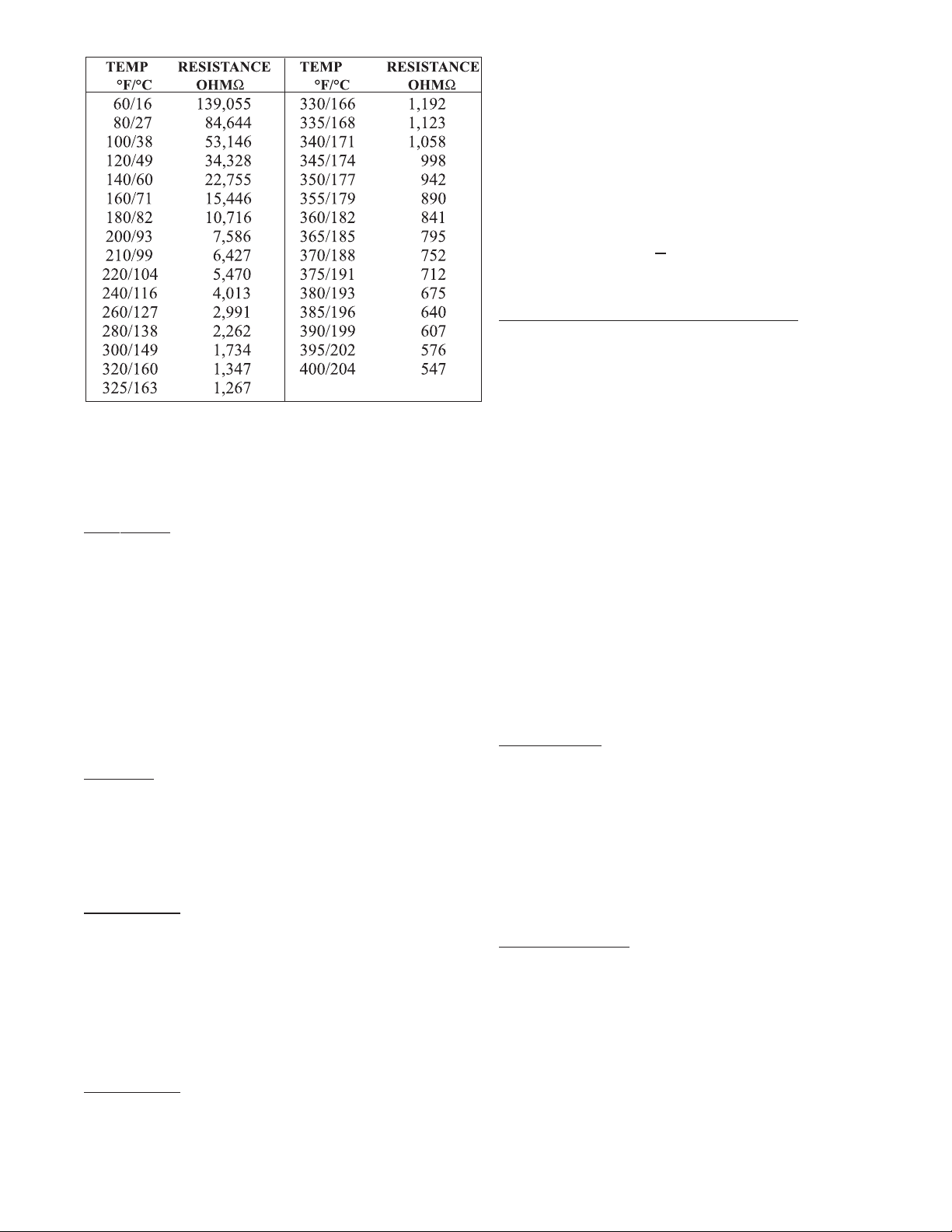
Probe:
The resistance of the probe will change as the tem-
perature changes. The resistance will decrease as the
temperature rises.
If the probe is suspect, check its resistance and the oil
temperature at which it was taken. Compare these
values on the probe resistance chart.
If the probe returns an open circuit or 0 Ohms read-
ing, it should be replaced. If the resistance varies more
than 30 Ohms when being checked between 325-
375°F the probe will give a false temperature reading
on the computer and should be calibrated (up to 10°F)
or replaced. However, it will continue to operate at a
slightly higher or lower temperature.
Allow the oil to cool and check the probe resistance