Pixii PowerShaper Indoor User manual

Shaping the power of the futureShaping the power of the future
Installation Guide
PowerShaper Indoor
Grid tied energy storage system
Document number: 14979, rev. 1.0
Issue date: 22.08.2023

2 Installation Guide ● PowerShaper Indoor
Document number: 14979, rev. 1.0
System safety and environmental precautions
Product warranty becomes invalid if following precautions are not followed during handling, storage,
installation, commissioning and operation of Pixii energy storage systems.
General precautions
Althoughthissystem incorporatesprotectivecircuits andothersecurity features,itmay still bedestroyed,
damaged, work poorly or shorten its lifetime if exposed to improper handling during transportation,
installation or operation. Always handle the system with care, use proper lifting techniques, do not roll,
climb or drill holes in the cabinet or enclosure.
Opening the equipment may cause serious injury even when theAC power is disconnected. Dangerous
voltage may be present inside, as system can be still running from batteries or capacitors may still be
charged.
Environmental precautions
Some devices can reach high temperatures during normal operation. It is very important to ensure that
airow through equipment is not blocked, lters are in good condition and fans can rotate freely. If other
equipment is installed in close proximity, secure that inlets and outlets are not blocked.
Electronic devices installed in the energy storage system are designed for indoor environment with
pollution degree 2. When installed in an outdoor enclosure (open or closed loop heat management
system), it is important to ensure, that the enclosure is closed and sealed during normal operation,
to avoid external air with increased level of humidity and dust from entering. In addition, in open loop
systems, lters maintenance must be properly planned. In case of indoor systems, operating environment
must be of pollution degree 2, without increased level of dust and humidity.
Installer is responsible to protect system against current surges, over-voltages, etc. caused by lightning,
electrostatic discharges, etc. To avoid system damage, it is mandatory to always install proper SPDs.
Installation precautions
Read carefully user documentation before installation and using this equipment. Follow all commands,
always use recommended tools and torque values as described. Commissioning and conguration of
equipment should be done only by Pixii personnel or by other authorized and qualied persons.
For safety reason, before you start installation, ensure all external power sources are disconnected, as
well as internal battery and load fuses/breakers. To avoid injuries caused by high leakage/touch current
you must always start installation by connecting earthing wire (PE), before you connect other AC input
wires (phases, neutral).
If system contains batteries, they represent major energy hazard. To avoid short circuit on batteries,
do not operate with full metallic tools close to battery poles. Be careful also about other objects (rings,
watches, necklaces, etc.).
All Pixii devices are certied according to international safety, environmental and EMC standards. If
any other devices will be installed inside this product, it might inuence parameters and violate original
approvals. Installer is responsible that during installation environmental properties of this device are not
impaired and installation is according to local regulations.

3
Installation Guide ● PowerShaper Indoor
Document number: 14979, rev. 1.0
Battery safety and environmental precautions
For safety reasons, installers are responsible for familiarizing themselves with the contents of battery
installation manual and all warnings before performing installation. Failure to observe the precautions
described in this section can cause serious injury to persons or damage to property.
Installation precautions
Read the battery installation manual before installing and operating the battery module.
•Disconnect the charging source prior to connecting or disconnecting battery terminals.
•Determine if battery is inadvertently grounded. If inadvertently grounded, remove source from
ground. Contact with any part of grounded battery can result in electrical shock. The likelihood of
such shock can be reduced if such grounds are removed during installation and maintenance.
Wear appropriate personal protective equipment when dealing with the battery module.
•Remove watches, rings, or other metal objects.
•Use tools with insulated handles.
•Wear rubber gloves and boots.
The battery module is heavy enough to cause severe injury.
Environmental precautions
Thebatterymodulemayleakcorrosiveelectrolyte.Avoidcontactwiththeleakingliquidorgas.Electrolyte
is corrosive and contact may cause skin irritation and chemical burns.
The battery module should not be disposed of with household waste at the end of its working life.
The battery module should be disposed of at a proper facility for environmentally safe recycling
General precautions
The voltage of this battery module is strong enough to cause electric shock.
•Do not disassemble the battery module.
•Do not touch the battery module with wet hands.
•Do not expose the battery module to moisture or liquids.
•Keep the battery module away from children and animals.
The battery module may explode.
•Do not subject the battery module to strong impacts.
•Do not crush or puncture the battery module.
•Do not dispose of the battery module in a re.
Keep the battery module away from open ame or ignition sources.
•Do not expose the battery module to temperatures in excess of 60°C.
•Do not place the battery module near a heat source, such as a replace.
•Do not expose the battery module to direct sunlight.
•Do not allow the battery connectors to touch conductive objects such as wires.
Risks of damage to the battery module.
•Do not allow the battery module to get in contact with liquids.
•Do not subject the battery module to high pressures.
•Do not place any objects on top of the battery module.

4 Installation Guide ● PowerShaper Indoor
Document number: 14979, rev. 1.0
Response to emergency situations
While the battery module comprises multiple battery cells that are designed to prevent hazards resulting
from failures, Pixii can not guarantee their absolute safety.
In the event that hazardous quantities of electrolyte are released, or in case of smoke, or re, leave the
battery room and contact the re brigade.
Leaking batteries
If the battery module leaks electrolyte, avoid contact with the leaking liquid or gas. Electrolyte is corrosive
and contact may cause skin irritation and chemical burns. If one is exposed to the leaked substance, do
these actions:
Inhalation:
Evacuate the contaminated area, and seek medical attention immediately.
Eye contact:
Rinse eyes with owing water for 15 minutes, and seek medical attention immediately.
Skin contact:
Wash the aected area thoroughly with soap and water, and seek medical attention immediately.
Ingestion:
Induce vomiting, and seek medical attention immediately
Rinse mouth and wash around the mouth with water.
Burns: If burns are caused, treat them accordingly. Likewise, immediate medical attention shall be
obtained.
Fire
In case of a re, make sure that an ABC or carbon dioxide extinguisher is nearby. If a re breaks out
where the battery module is installed, do these actions:
1. Extinguish the re before the battery module catches re.
2. If the battery module has caught re, do not try to extinguish the re. Evacuate people immediately.
Wet batteries
If the battery module is wet or submerged in water, do not try to access it. Contact Pixii or your distributor
for technical assistance.
Damaged batteries
Damaged batteries are dangerous and must be handled with extreme caution. They are not t for use
and may pose a danger to people or property. If the battery module seems to be damaged, pack it in its
original container, and then return it to Pixii or your distributor.
!!! Caution !!!
Damaged batteries may leak electrolyte or produce ammable gas. If you suspect such damage,
immediately contact Pixii for advice and information.
!!! Warning !!!
The battery module may catch re when heated above 150°C.
If the battery catches re, it will produce noxious and poisonous gases. Do not approach.

5
Installation Guide ● PowerShaper Indoor
Document number: 14979, rev. 1.0
Information contained in this document can be changed without notice and does not represent a
commitment on the part of Pixii.
No part of this document may be reproduced, copied or transmitted (electronic or mechanic, including
photocopying and recording) for any purpose to 3rd party without the explicit written permission of Pixii.
Copyright © Pixii 2023
Revision Date Comment
1.0 2023-22-08 Initial

6 Installation Guide ● PowerShaper Indoor
Document number: 14979, rev. 1.0
Table of Contents
1 Introduction� � � � � � � � � � � � � � � � � � � � � � � � � � � � � � � � � � � � � � � � � � � � � � � � �8
1.1 Recommended tools and torque . . . . . . . . . . . . . . . . . . . . . . . . . . . . . . . . . . . . . . . . . 8
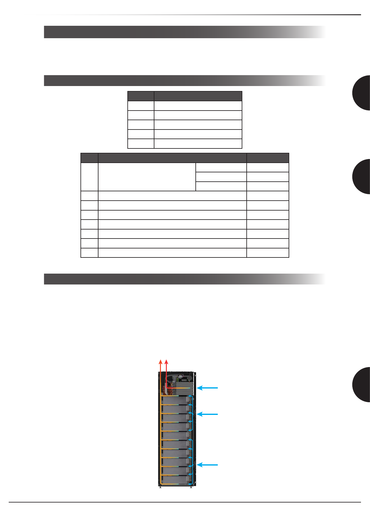
1.2 Thermal management system (TMS). . . . . . . . . . . . . . . . . . . . . . . . . . . . . . . . . . . . . . 8
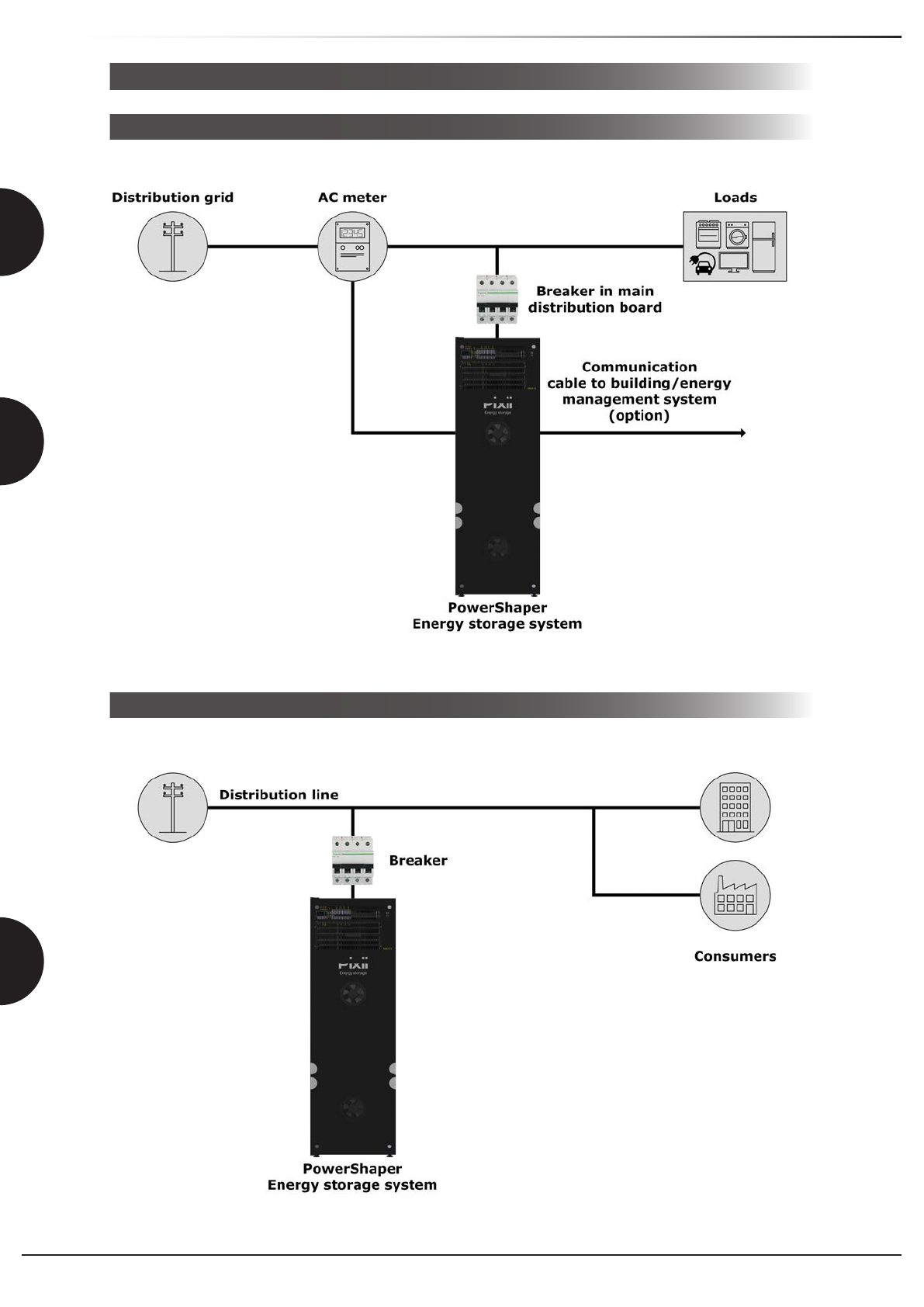
1.3 Installation block diagram . . . . . . . . . . . . . . . . . . . . . . . . . . . . . . . . . . . . . . . . . . . . . . 9
1.3.1 Behind the meter. . . . . . . . . . . . . . . . . . . . . . . . . . . . . . . . . . . . . . . . . . . . . . . . . . . . . . . . .9
1.3.2 In front of the meter. . . . . . . . . . . . . . . . . . . . . . . . . . . . . . . . . . . . . . . . . . . . . . . . . . . . . . .9
1.4 System ratings. . . . . . . . . . . . . . . . . . . . . . . . . . . . . . . . . . . . . . . . . . . . . . . . . . . . . . 10
1.4.1 Electrical specications . . . . . . . . . . . . . . . . . . . . . . . . . . . . . . . . . . . . . . . . . . . . . . . . . . .10
1.4.2 Environmental specications. . . . . . . . . . . . . . . . . . . . . . . . . . . . . . . . . . . . . . . . . . . . . . .11
1.4.3 Mechanical specications . . . . . . . . . . . . . . . . . . . . . . . . . . . . . . . . . . . . . . . . . . . . . . . . .12
1.4.4 Fuse list. . . . . . . . . . . . . . . . . . . . . . . . . . . . . . . . . . . . . . . . . . . . . . . . . . . . . . . . . . . . . . .13
1.5 Anti-islanding . . . . . . . . . . . . . . . . . . . . . . . . . . . . . . . . . . . . . . . . . . . . . . . . . . . . . . . 13
2 Preparing installation site � � � � � � � � � � � � � � � � � � � � � � � � � � � � � � � � � � � �14
2.1 Pre-installation steps . . . . . . . . . . . . . . . . . . . . . . . . . . . . . . . . . . . . . . . . . . . . . . . . . 14
2.2 Recommended upstream breaker and input cable . . . . . . . . . . . . . . . . . . . . . . . . . . 15
2.3 Mains input metering . . . . . . . . . . . . . . . . . . . . . . . . . . . . . . . . . . . . . . . . . . . . . . . . . 15
2.3.1 AMS energy meter. . . . . . . . . . . . . . . . . . . . . . . . . . . . . . . . . . . . . . . . . . . . . . . . . . . . . . .15
2.3.2 Industrial grade energy meter . . . . . . . . . . . . . . . . . . . . . . . . . . . . . . . . . . . . . . . . . . . . . .16
3 Mechanical installation� � � � � � � � � � � � � � � � � � � � � � � � � � � � � � � � � � � � � � �17
3.1 Preparing site for installation . . . . . . . . . . . . . . . . . . . . . . . . . . . . . . . . . . . . . . . . . . . 17
3.2 Positioning . . . . . . . . . . . . . . . . . . . . . . . . . . . . . . . . . . . . . . . . . . . . . . . . . . . . . . . . . 17
3.2.1 Moving . . . . . . . . . . . . . . . . . . . . . . . . . . . . . . . . . . . . . . . . . . . . . . . . . . . . . . . . . . . . . . . .17
3.2.2 Lifting (Optional) . . . . . . . . . . . . . . . . . . . . . . . . . . . . . . . . . . . . . . . . . . . . . . . . . . . . . . . .17
4 Electrical installation � � � � � � � � � � � � � � � � � � � � � � � � � � � � � � � � � � � � � � � �18
4.1 Preparation . . . . . . . . . . . . . . . . . . . . . . . . . . . . . . . . . . . . . . . . . . . . . . . . . . . . . . . . 18
4.2 Protective bonding. . . . . . . . . . . . . . . . . . . . . . . . . . . . . . . . . . . . . . . . . . . . . . . . . . . 19
4.3 AC Mains Connection . . . . . . . . . . . . . . . . . . . . . . . . . . . . . . . . . . . . . . . . . . . . . . . . 20
4.3.1 TN-S/TT (230/400Vac) network. . . . . . . . . . . . . . . . . . . . . . . . . . . . . . . . . . . . . . . . . . . . .20
4.4 Emergency disconnect switch . . . . . . . . . . . . . . . . . . . . . . . . . . . . . . . . . . . . . . . . . . 21
4.5 Custom alarm connection . . . . . . . . . . . . . . . . . . . . . . . . . . . . . . . . . . . . . . . . . . . . . 22
4.5.1 Separate alarm . . . . . . . . . . . . . . . . . . . . . . . . . . . . . . . . . . . . . . . . . . . . . . . . . . . . . . . . .23
4.5.2 Common alarm . . . . . . . . . . . . . . . . . . . . . . . . . . . . . . . . . . . . . . . . . . . . . . . . . . . . . . . . .23
4.6 External communication. . . . . . . . . . . . . . . . . . . . . . . . . . . . . . . . . . . . . . . . . . . . . . . 24
4.6.1 Wi-Fi Access Point. . . . . . . . . . . . . . . . . . . . . . . . . . . . . . . . . . . . . . . . . . . . . . . . . . . . . . .24
4.6.2 Ethernet connection. . . . . . . . . . . . . . . . . . . . . . . . . . . . . . . . . . . . . . . . . . . . . . . . . . . . . .24
4.7 AC meter connection . . . . . . . . . . . . . . . . . . . . . . . . . . . . . . . . . . . . . . . . . . . . . . . . . 25
4.7.1 AMS energy meter. . . . . . . . . . . . . . . . . . . . . . . . . . . . . . . . . . . . . . . . . . . . . . . . . . . . . . .25
4.7.2 Industrial grade energy meter . . . . . . . . . . . . . . . . . . . . . . . . . . . . . . . . . . . . . . . . . . . . . .25
4.8 Installing batteries . . . . . . . . . . . . . . . . . . . . . . . . . . . . . . . . . . . . . . . . . . . . . . . . . . . 26
4.8.1 Polarium . . . . . . . . . . . . . . . . . . . . . . . . . . . . . . . . . . . . . . . . . . . . . . . . . . . . . . . . . . . . . .26
4.8.2 Shoto. . . . . . . . . . . . . . . . . . . . . . . . . . . . . . . . . . . . . . . . . . . . . . . . . . . . . . . . . . . . . . . . .29
4.8.3 Battery Com converter. . . . . . . . . . . . . . . . . . . . . . . . . . . . . . . . . . . . . . . . . . . . . . . . . . . .32
4.9 Power modules . . . . . . . . . . . . . . . . . . . . . . . . . . . . . . . . . . . . . . . . . . . . . . . . . . . . . 33
4.9.1 Installing module . . . . . . . . . . . . . . . . . . . . . . . . . . . . . . . . . . . . . . . . . . . . . . . . . . . . . . . .33
4.9.2 Removing module . . . . . . . . . . . . . . . . . . . . . . . . . . . . . . . . . . . . . . . . . . . . . . . . . . . . . . .33
4.10 System label . . . . . . . . . . . . . . . . . . . . . . . . . . . . . . . . . . . . . . . . . . . . . . . . . . . . . . 34
4.11 Finalization. . . . . . . . . . . . . . . . . . . . . . . . . . . . . . . . . . . . . . . . . . . . . . . . . . . . . . . . 34
5 Commissioning procedure � � � � � � � � � � � � � � � � � � � � � � � � � � � � � � � � � � �35
6 Maintenance � � � � � � � � � � � � � � � � � � � � � � � � � � � � � � � � � � � � � � � � � � � � � � �35

7
Installation Guide ● PowerShaper Indoor
Document number: 14979, rev. 1.0
6.1 System. . . . . . . . . . . . . . . . . . . . . . . . . . . . . . . . . . . . . . . . . . . . . . . . . . . . . . . . . . . . 35

8 Installation Guide ● PowerShaper Indoor
Document number: 14979, rev. 1.0
Introduction
1 Introduction
This document describe step by step installation, commissioning and start-up of energy storage system.
Read it carefully and follow all recommendations to be sure system is running in correct environment
under good conditions and installation reached all safety requirements.
1�1 Recommended tools and torque
Tool
W Wrench
PZ2 Pozidriv screwdriver
Flat Flat screwdriver
T-W Torque wrench
T-PZ2 Torque Pozidriv screwdriver
1�2 Thermal management system (TMS)
Cabinet thermal management system provides appropriate thermal conditions inside the cabinet.
Solution is integrated on the cabinet door with controlled air ow inside the cabinet.
Fan TMS using free cooling principle which is open loop system. Outside cold air is pulled into the battery
section through the two inlet fans and hot air is pushed out through the top rear side of the cabinet.
Two inlet fans mounted on the door are cooling the batteries, while the modules on the top are self-
cooling and suck cold air with their own small fans through the ventilation on the top of the door.
With moderate ambient temperatures or low power dissipation the fans will be running at low speed. As
the ambient temperature or internal power dissipation increases the fans speed will increase.
Figure 1.1 Indoor cabinet air ow diagram (side view)
Type & Size Torque
T1 TERMINAL BLOCK OTL 50 - Y/G
1.5 - 2.5mm21.5 Nm
4 - 10mm25.0 Nm
16 - 50mm210.0 Nm
T2 AC Mains input MCB (1-50mm2)3.5 Nm
T3 Polarium batteries (DC cables) 15.0 Nm
T4 Shoto batteries (DC cables) 6.0 Nm
T4 M6 self tapping screw 9.8 Nm
T5 M6 Hex screw (Protective bonding) 6.0 Nm
T6 WDU 2.5 Terminals (Emergency switch) 0.4 - 0.8 Nm
T7 DLD 2.5 Terminals (Relays, Modbus) 0.4 - 0.6 Nm
Table 1. Recommended tools and torques

9
Installation Guide ● PowerShaper Indoor
Document number: 14979, rev. 1.0
Introduction
1�3 Installation block diagram
1�3�1 Behind the meter
Figure 1.2 Single line installation block diagram - behind the meter
Figure 1.3 Single line installation block diagram - in front of the meter
1�3�2 In front of the meter

10 Installation Guide ● PowerShaper Indoor
Document number: 14979, rev. 1.0
Introduction
1�4 System ratings
1�4�1 Electrical specications
The PowerShaper consist of modular converters, each of them providing transformers with Reinforced
insulation between AC side and the DC side.
AC Mains Type TN
Max. Active Power (charge and discharge) 50kW1,3/40kW2
Max. Apparent Power (charge and discharge) 50kVA1,3/40kVA2
AC voltage 400/230V, 3Ph+N+PE
Max. AC current 83Arms, 3Ph+N+PE
Nominal AC current 72Arms, 3Ph+N+PE
Frequency range 45Hz to 66Hz
Cos jrange 0.5 inductively to 0.5 capacitively
Protective class Class I
Overvoltage category OVC III
Max. short circuit current 10kA
Type of short-circuit protective device MCB
Max. Energy 48kWh1/103.2kWh2/51.2kWh3
Max. DC voltage 44V to 58V
Max. DC current 1000A
Voltage uctuations and icker:
Pst Plt Z
Measured using Ztest 0,645 0,603 0,013Ω+j0,002Ω
Maximum permissible network impedance, Zmax - - 0,093Ω+j0,093Ω
Type of the battery 1Polarium SLB48-100 2Polarium SLB48-250 3Shoto SDA10-48400
Nominal capacity 100Ah 250Ah 100Ah
Nominal energy 4.8kWh 12.9kWh 5.12kWh
Operating voltage 39V-54.75V 35V-58.8V 40V-57.7V
Max. charge/discharge
current 100A
Table 2. Electrical specications

11
Installation Guide ● PowerShaper Indoor
Document number: 14979, rev. 1.0
Introduction
1�4�2 Environmental specications
Type of cabinet Indoor
Operating temperatures +5°C to +40°C
Humidity 5% to 85% RH (non-condensing)
Storage and transportation temperatures -30°C to +60°C*
Storage and transportation humidity 5% to 55% RH (non-condensing)
Storage (less than 12 months) State of Charge (SoC): 85%
Acoustic noise (maximum) <50dBA at 1m distance
Maximum altitude 2000m
Ingress protection rating IP20
Pollution degree 2
Wet locations No
Current (inrush) 25Apeak
Maximum output fault current 200Apeak/1ms
Inverter topology Isolated
Env. cat. (IEC 62477-1) Indoor conditioned
* Without batteries installed.
Table 3. Environmental specications

12 Installation Guide ● PowerShaper Indoor
Document number: 14979, rev. 1.0
Introduction
Height (feet included) 1991mm
Width 598mm
Depth 651mm
Weight (without modules and batteries) 150 kg
Module 2 kg
Shoto 3U battery 43 kg
Polarium 3U battery 38 kg
Polarium 4U battery (250Ah) 64 kg
Extension kit for 4U batteries 15 kg
1�4�3 Mechanical specications
Figure 1.4 Mechanical specication
Table 4. Dimensions and weights
1991
651
598

13
Installation Guide ● PowerShaper Indoor
Document number: 14979, rev. 1.0
Introduction
Type Manufacturer Manufacturer part number
-FC1 100A 4-pole C-curve Schneider A9N18480
-FC13 10A 6.3x32mm fast 10kA Eaton BK-AHC-10-R
-FC20 10A 6.4x32mm fast 10kA Bussmann ABC-10-R
-FC21 10A 6.4x32mm fast 10kA Bussmann ABC-10-R
-F201 0,5A 5x20mm slow Littelfuse 0477.500MXP
-F202 3,15A 5x20mm slow Littelfuse 04773.15MXP
-F203 3,15A 5x20mm slow Littelfuse 04773.15MXP
1�4�4 Fuse list
1�5 Anti-islanding
ThePowerShaperincorporatesbothpassiveandactiveanti-islandingfunctionality.Thepassivemethods
included are under/over voltage, under/over frequency and rate of change of frequency detection. The
active anti-islanding functionality uses the frequency shift method based on feedback from frequency
variation in combination with a small reactive power perturbation. The active anti-islanding function may
be disabled for grid codes not accepting such means of islanding detection.
NOTE:
Please consult replacement of any fuse or circuit breaker with Pixii rst.
Table 5. Fuse list

14 Installation Guide ● PowerShaper Indoor
Document number: 14979, rev. 1.0
Preparing installation site
2 Preparing installation site
2�1 Pre-installation steps
1� Organize installation site
•Mounting base strong enough to carry weight of fully equipped system (see Table 4)
•Clearances for cabinet access
2� Prepare installation tools
•Use insulated tools suitable for electrical installations
•Recommended tools list is in chapter "Tool" on page 8
3� Prepare AC Mains supply
•Correct type of AC Mains supply (TN-S)
•Correct rating of AC input cables and external fuses
•AC Mains supply meter
NOTE:
It is strictly required to follow local regulations if separation distances larger than the table above are
required.
NOTE:
The energy storage system is installed indoor, automatic sprinkler system is highly recommended and
sometimes required. Local regulations must be adhered to.
Minimum distance Suggested distance
Front 70cm 100cm
Rear 10cm 25cm
Top 50cm 90cm
Sides 0 0

15
Installation Guide ● PowerShaper Indoor
Document number: 14979, rev. 1.0
Preparing installation site
2�3 Mains input metering
To secure correct operation, system must have actual readings from mains input AC meter. Therefore
compatible meter must be installed on site. Measured values are important to perform autonomous
operation functionality such as peak shaving and others. Pixii system has support for communicating
with 2 dierent types of meters.
2�3�1 AMS energy meter
AMS meter allows for monitoring consumption and production down to a few second intervals through
the HAN-port (M-Bus) according to Norwegian HAN-port specication. The HAN-port is closed by
default. Contact your local network company to open it. Before opening the HAN-port, the network
company will rst ask some questions related to securing the gate for privacy reasons. For connecting to
the HAN-port a standard Ethernet cable with RJ45 connectors is required. Maximum practical distance
at highest speed is 350 meters.
Supported AC Meters
•Aidon
•Kamstrup
•Nuri
NOTE:
Measured data are used at the customer's own risk. The distribution company or Pixii is not responsible
for any losses resulting from its use, including losses due to errors or omissions in the data.
2�2 Recommended upstream breaker and input cable
To reach stable system operation, it is very important to use proper input cable and upstream breaker.
Recommended values for dierent types of networks can be nd in table below.
AC Mains Type Number of
Power Shelves Maximum
current Upstream
breaker Input cable
230/400Vac
3-phase, TN-S network
5-wire system 583A 100A C-curve 35mm2 - 50mm2
(CU)
230/400Vac
3-phase, TT network
4-wire system
NOTE:
If dierent number of power shelves or breaker with lower rating needs to be used from any reason,
discuss possibilities with Pixii.
NOTE:
Breaking capacity of input breaker installed in system is 10kA, upstream breaker breaking capacity
must correspond to AC grid conditions at the point of installation.
NOTE:
Cable type, upstream breaker and RCD depends on local conditions and regulations.
!!! WARNING !!!
System is designed to operate on 1-phase or 3-phase networks� It is strictly forbidden to
connect multiple single-phases to the system�
CAUTION:
For TT-networks, the installation of an RCD is required.

16 Installation Guide ● PowerShaper Indoor
Document number: 14979, rev. 1.0
Preparing installation site
2�3�2 Industrial grade energy meter
The Pixii system has support for an energy meters from dierent manufacturers. Depending on type of
the meter, external measuring transformers may be required. Currently, communication via Modbus/
RTU (RS485) is supported. This means that a cable (2-wire at least) needs to be connected from the
meter to the controller in the system. Maximum practical distance is 300 meters.
Supported AC Meters
•Phoenix Contact:
»EEM-EM357
»EEM-EM355
»EEM-MA370-R
»EEM-MA371-R
•Schneider:
»iEM 31xx series
»iEM 32xx series
»iEM 33xx series
•Acuvim II series | Accuenergy (Modbus/TCP available)
•Janitza:
»B23 312-10J
»B24 312-10J
»UMG series

17
Installation Guide ● PowerShaper Indoor
Document number: 14979, rev. 1.0
Mechanical installation
3 Mechanical installation
3�1 Preparing site for installation
To secure correct system operation, cabinet must be properly xed to solid horizontal leveled surface.
3�2 Positioning
Figure 3.1 Mount lifting lugs Figure 3.2 Fix chains or straps
Figure 3.3 Adjusting the feet
!!! WARNING !!!
Do NOT use any other technique to lift the cabinet because of imminent damage�
Never lift cabinet with opened door�
Do NOT lift cabinet with installed modules and batteries�
3�2�2 Lifting (Optional)
NOTE:
Remove lifting lugs after positioning the cabinet.
NOTE:
Lifting lugs are optional equipment and must be ordered separately.
!!! WARNING !!!
Construction of the cabinet may be heavy and unbalanced� It is strictly recommended to
moving the cabinet in two persons�
3�2�1 Moving
Move the cabinet on pallet using forklift near its position and lay down on the oor manually.
•Mount attached lifting lugs with M10x16 bolt and M10 plain washer (see Figure 3.1).
•Fix chains or straps (minimum length 1 meter) to all lifting lugs (see Figure 3.2), securely lift and
move system to the desired position.
•By twisting cabinet feet adjust correct position (see Figure 3.3).

18 Installation Guide ● PowerShaper Indoor
Document number: 14979, rev. 1.0
Electrical installation
4 Electrical installation
For safety reason, before you start installation, ensure all external power sources are disconnected, as
well as internal battery and load fuses/breakers. To avoid injuries caused by high leakage/touch current
you must always start installation by connecting earthing wire (PE), before you connect other AC input
wires (phases, neutral).
4�1 Preparation
Remove the front cover by releasing 4x M6x10 torx screws.
Figure 4.1 Removing the front cover
NOTE:
Keep xings and cover at safe place, as you need them later!

19
Installation Guide ● PowerShaper Indoor
Document number: 14979, rev. 1.0
Electrical installation
NOTE:
Do NOT interconnect bonding busbars in multiple cabinets in multicabinet installation. Connect
separate bonding cable to each cabinet in multicabinet installation.
4�2 Protective bonding
It is necessary to interconnect cabinet chassis with main earthing point, to ensure equal potential
throughout the installation thus preventing a hazardous potential dierence occurring between such
parts in the event of a fault.
Connect bonding cable from main earthing point to the cabinet bonding point (two options on the left
side of the roof) with M6 lug.
Figure 4.2 Protective bonding
Main earthing point

20 Installation Guide ● PowerShaper Indoor
Document number: 14979, rev. 1.0
Electrical installation
4�3 AC Mains Connection
4�3�1 TN-S/TT (230/400Vac) network
•Connect PE wire to terminals X1. Use torque T1.
Conductor (CU) 1.5mm2 - 50mm2.
•Connect phase wires (L1, L2, L3) and neutral wire (N) to MCB FC1. Use torque T2.
Conductor (CU) 1.0mm2 - 50mm2.
Figure 4.3 Mains connection
Table of contents
Other Pixii Storage manuals