pizzato FR Series User manual

Sheet:
Date:
:
15367-0-en-2.1.0
2017/12/26
FR 593
Article:
Description: Interruptor de seguridad con actuador separado
© 2017 Copyright Pizzato Elettrica.Technical modifications and errors reserved. The data quoted in this sheet are carefully checked and represent typical series values.
Descriptions of device and its applications, the control contexts, details on external controls, installation and operating information are given to the best of our knowledge. This does not mean however that any assured
properties or other claims under liability law that extend beyond the “General Sales Terms” as stated in the Pizzato Elettrica general catalogue may be derived. The user is not absolved of his obligation to examine our
information and recommendations before using them for his own purposes.
Alojamiento:
Carcasa de polímero, entrada de conducto de rosca PG 13,5 (serie FR)
Caracteristicas Generales:
Ambient temperature: from -25°C to +80°C
Max actuation frequency: 3600 operations cycles/hour Mechanical endurance:
20 million operations cycles
Contact block characteristics:
Acción rápida 1NA + 1NC (B5)
.
Travel diagram:
Apertura positiva:
Si
Cross section of the conductors
(flexible copper wire):
min.1x0,5mm2(1xAWG20)
max.2x1,5mm2(2xAWG16)
Device screw tightening torques:
Coverscrews:0,7...0,9Nm
Head screws: 0,5 ... 0,7Nm
Lever screws: 0,7 ... 0,9 Nm
Contactblocksscrews: 0,6...0,8Nm
Plugs:
1,2...1,6Nm(M20/PG13,5)
1 ... 1,4 Nm (M16/PG11)
In conformity with requirements requested by: Activating forces:
Low Voltage Directive 2014/35/EU
Electromagnetic
Compatibility
Directive
2014/30/EU
In conformity with standards:
Min.
: 0,06 Nm
Positive opening: 0,25 Nm
IEC 60947-5-1, EN 60947-5-1, EN 60947-1, EN 50047, IEC 60204-1, EN 60204-1,
EN ISO 14119, EN ISO 12100, IEC 60529, EN 60529, UL 508,CSA 22.2 No. 14.
Approvals:
IEC 60947-5-1, UL 508, CSA 22.2 No. 14, GB14048.5-2001.
Markings and quality marks:
Electricaldata: Utilization categories:
Thermal current (Ith): 10 A
Rated insulation voltage (Ui): 400 Vac 500 Vdc Rated
impulse withstand voltage (Uimp): 4 kV
Conditional shot circuit current: 1000 A according to EN 60947-5-1
Protection
against short circuits: fuse 10 A 500 V type aM
Pollution degree: 3
Alternatecurrent:AC15(50...60Hz)
Ue(V)
250 400
Ie(A) 6 4
Direct current: DC13
Ue(V) 24 125 250
Ie(A) 6 1,1 0,4

Sheet:
Date:
:
15367-0-en-2.1.0
2017/12/26
FR 593
Article:
Description: Interruptor de seguridad con actuador separado
4/1
2
e-mail: info@pizzato.com web
site: www.pizzato.com Phone:
+39.0424.470.930
Fax: +39.0424.470.955
1
INFORMATION ON THIS DOCUMENT
1.1
Function
The present instruction manual provides information on installation, connection and
safeuseforthefollowingarticles:FR ••93, FX ••93, FK ••93, FR ••92, FX ••92, FK ••92,
FW ••92.
1.2
Target audience
The operations described in this instruction manual must be carried out by qualified
personnel only, who are fully capable of understanding them, and with the technical
qualifications required for operating the machines and plants in which the safety de-
vices are to be installed.
1.3
Application field
These instructions apply exclusively to the products listed in paragraph Function, and
their accessories.
1.4
Original instructions
The Italian language version is the original set of instructions for the device. Versions
provided in other languages are translations of the original instructions.
2
SYMBOLS USED
This symbol indicates any relevant additional information.
Attention: Any failure to observe this warning note can cause damage or mal-
function, including possible loss of the safety function.
3
DESCRIPTION
3.1
Device description
The safety devices described in this manual are defined as coded, type 2 mechanical
interlocking devices acc. to EN ISO 14119.
The safety switches with separate actuator to which these usage instructions refer are
safety devices designed and implemented for the control of gates, guards, enclosures,
and doors in general, which are installed to protect dangerous parts of machines
without inertia.
The actuator is installed on the moving part of the guard in such a way that it is
extracted from the switch each time the guard is opened.
3.2
Intended use of the device
-
The device described in this manual is designed tobeapplied on industrialmachines
for state monitoring of movable guards.
-
The direct sale of this device to the public is prohibited. Installation and use must be
carried out by qualified personnel only.
-
The use of the device for purposes other than those specified in this manual is
prohibited.
-
Any use other than as expressly specified in this manual shall be considered
unintended by the manufacturer.
-
Also considered unintended use:
a)
using the device after having made structural, technical, or electrical modifications to
it;
b)
using the product in a field of application other than as described in paragraph
TEChNICAL DATA.
4 INSTALLATION INSTRUCTIONS
Attention: Installing a protective device is not sufficient to ensure operator safety
or compliance with machine safety standards or directives. Before installing a protec-
tive device, perform a specific risk analysis in accordance with the key health and
safety requirements in the Machinery Directive. The manufacturer guarantees only the
safe functioning of the product to which this instruction manual refers, and not the
functional safety of the entire machine or entire plant.
4.1
Selection of the actuator type
The switch is activated by a low level coded actuator. Please make sure to use only
the actuator provided with the switch or use one of the following actuators: VF KEYD,
VF KEYD1, VF KEYD2, VF KEYD3, VF KEYD5, VF KEYD6, VF KEYD7, VF KEYD8,
VF KEYD10, VF KEYD11.
The use of any other actuator does not guarantee the safety of the system.
Attention: Any other actuators present in the same place where the device has
been installed must be segregated and kept under strict control in order to avoid any
bypassing of the safety device. If new actuators are fitted, the original actuators must
be disposed of or rendered inoperable.
4.2
Device head orientation
It is possible to adjust the position of the device head in order to turn it to the position
best suited to the application.
Completely removing the head fixing screws allows orientation in 90° rotations.
Attention:Once adjustment is complete, re-tighten all head screws with a torque
between 0.5 and 0.7 Nm.
For FR ••92, FX ••92, FK ••92, FW ••92 only: once the device is in its definitive
configuration, you must replace two of the head fixing screws on the body, with two
one-way tamper-proof screws, provided with the device. The two tamper-proof screws
must be screwed onto diametrically opposed holes on the head. This must be carried
out before commissioning the machine.
The switch head has two actuator inputs: one perpendicular, and the other parallel to
the device body. Once the actuator input direction has been selected, the unused input
holemust besealed, using the appropriate cap supplied. It is possible touse one

Sheet:
Date:
:
15367-0-en-2.1.0
2017/12/26
FR 593
Article:
Description: Interruptor de seguridad con actuador separado
5/1
2
single hole at a time, with one single actuator.
4.3
Fixing of the device
Attention: Always affix the device with at least 2 M4 (for FR •••, FX •••, FK •••
series) or M5 screws (for FW ••• series). Always use screws with a resistance class
of 4.6 or higher, and flat seating heads. Install the screws with medium resistance
thread lock, and a number of threads engaged equal to or greater than the screw
diameter. The device must never be fixed with less than 2 screws. For FR •••, FK •••,
FW ••• series, we recommend using under head washers for the fixing screws on the
device body.
The tightening torque of the M4 and M5 screws must be between 2 and 2.5 Nm.
It is advisable to install the device in the top part of the door, in order to prevent any
dirt or work residues from getting inside the hole where the actuator is to be
introduced. In order to avoid device bypassing it is advisable to fix the device body to
the machine frame so that it cannot be removed.
4.4
Fixing the actuator to the guard
Attention: As required by EN ISO 14119, the actuator must be fixed immovably
to the door frame.
Install the actuator so that its edge does not protrude dangerously into the
operator working area when the door is open.
Always affix the actuator with 2 M4 (for items VF KEYD, VF KEYD1, VF KEYD2, VF
KEYD3) or M5 screws (for items VF KEYD5, VF KEYD6, VF KEYD7, VF KEYD8,
VF KEYD10, VF KEYD11) of resistance class 4.6 or higher, and with flat seating
heads. Install the screws with medium resistance thread lock, and a number of threads
engaged equal to or greater than the screw diameter. The actuator must never be
fixed with fewer than 2 screws. The tightening torque of the M4 and M5 screws must
be between 1.2 and 1.6 Nm
Do not deform or modify the actuator during installation for any reason.
For correct fixing, other means can also be used, such as rivets, non-removable
security screws (one-way), or other equivalent fixing system, provided that it can
ensure adequate fixing.
4.5
Switch-actuator alignment
Before commissioning the machine, and periodically, check that the alignment be-
tween switch and its actuator is correct. The actuator must not impact the inlet area on
the switch, and must not be used as a centring device for the mobile guard.
Do not use a hammer for the adjustments, unscrew the screws and adjust the device
manually, then tighten it in position.
4.6
Electrical connections
Attention: the safety circuit must be connected to the safety contacts (11-12, 21- 22,
31-32). The auxiliary contacts (13-14, 23-24, 33-34) must be used for signalling only.
To gain access to the contact block terminals, open the cover on the front switch part,
removing the fixing screws. Once cabling work is complete, always re-close the cover.
5 OPERATION
Once the device is installed tothe machine and the actuator tothe opening guard, and
electrical connections have been made (as described in paragraph "INSTALLATION
INSTRUCTIONS"), extracting the switch actuator must initiate a stop of the machine
and related dangerous moving elements.
Subsequent machine restart shall be possible only once the actuator has been
reinserted to the device.
5.1 Access monitoring
This switch alone is not sufficient to protect any operators or maintenance engineers
in the event that they are able to physically enter the danger area with their whole
body, since any unintentional closing of a guard behind them could allow the machine
to be restarted. If this device is solely responsible for authorising machine re-start,

Sheet:
Date:
:
15367-0-en-2.1.0
2017/12/26
FR 593
Article:
Description: Interruptor de seguridad con actuador separado
6/1
2
additional protection systems must be provided (lock out/tag out) to mitigate risk.
Please contact technical assistance for more information (see SUPPORT paragraph).
6 INSTRUCTIONS FOR PROPER USE
6.1
Installation
-
Tighten the fixing screws of electrical conductors to a torque from 0.6 to 0.8 Nm.
-
Do not stress the device with bending and torsion.
-
Do not modify the device for any reason.
-
Do not exceed the tightening torques specified in the present manual.
-
The device carries out an operator protection function. Any inadequate installation
or tampering can cause serious injuries and even death, property damage, and
economic losses.
-
These devices must not be bypassed, removed, turned or disabled in any other way.
-
If the machine where the device is installed is used for a purpose other than that
specified, the device may not provide the operator with efficient protection.
-
The safety category of the system (according toEN ISO 13849-1), including the safe-
ty device, also depends on the external components connected to it and their type.
-
Before installation, make sure the device is not damaged in any part.
-
Avoid excessive bending of connection cables in order to prevent any short circuits
or power failures.
-
Do not paint or varnish the device.
-
Do not drill the device.
-
Do not use the device as a support or rest for other structures, such as raceways,
sliding guides or similar.
-
Before commissioning, make sure that the entire machine (or system) complies with
all applicable standards and EMC directive requirements.
-
The fitting surface of the device must always be smooth and clean.
-
The documents necessary for a correct installation and maintenance are always
available in the following languages: English, French, German andItalian.
-
Should the installer be unable to fully understand the documents, the product must
not be installed and the necessary assistance may be requested (see paragraph
SUPPORT).
- When the device is installed on a mobile frame and the actuator is installed on a
mobile door, ensure that the device cannot be damaged by simultaneous opening of
the frame and the door.
-
Always attach the following instructions to the manual of the machine in which the
device is installed.
-
These operating instructions must be kept available for consultation at any time and
for the whole period of use of the device.
6.2
Do not use in the following environments
Attention: Do not use in environments where dust and dirt may in any way
penetrate the head and deposit there. Do not use in particular where metal dust,
concrete or chemicals are spread.
-
In environments where continual changes in temperature cause the formation of
condensation inside the device.
-
In environments where the application causes collisions, impacts or strong vibrations
to the device.
-
In environments containing explosive or inflammable gases or dusts.
-
In environments where ice can form on the device.
-
In environments containing strongly aggressive chemicals, where the products used
coming into contact with the device may impair its physical or functional integrity.
6.3
Mechanical stop
Attention: The door must always be provided with an independent end-limit
mechanical stop at limit of travel.
Do not use the device as mechanical stop for the door.
6.4
Maintenance and functional tests
Attention: Do not disassemble or try to repair the device. In case of any
malfunction or failure, replace the entire device.
Attention: In case of damages or wear it is necessary to change the whole
device including its actuator. Correct operation cannot be guaranteed when the device
is deformed or damaged.
-
The installer is responsible for establishing the sequence of functional tests towhich
the device is to be subjected before the machine is started up and during mainte-
nance intervals.
-
The sequence of the functional tests can vary depending on the machine complexity
and circuit diagram, therefore the functional test sequence detailed below is to be
considered as minimal and not exhaustive.
-
Perform the following sequence of checks before the machine is commissionedand
at least once a year (or after a prolonged shutdown):
1)
Open the guard while the machine is moving. The machine must stop imme-
diately. The stopping time of the machine must be always shorter than the time
required by the operator for opening the guard and reaching the dangerousparts.
2)
Try to start the machine while the guard is open. The machine must not start.
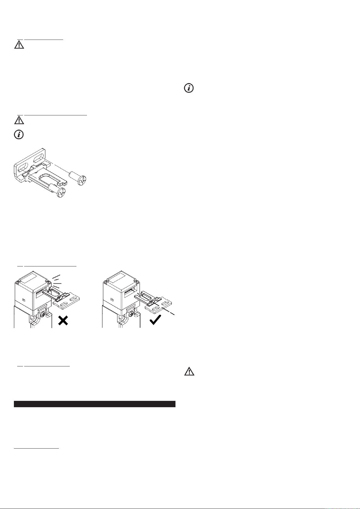
3)
Check correct actuator to device alignment. If the actuator inlet is worn, replace
the entire device and actuator assembly.
4)
All external parts must be undamaged.
5)
If the device is damaged, replace it completely.
6)
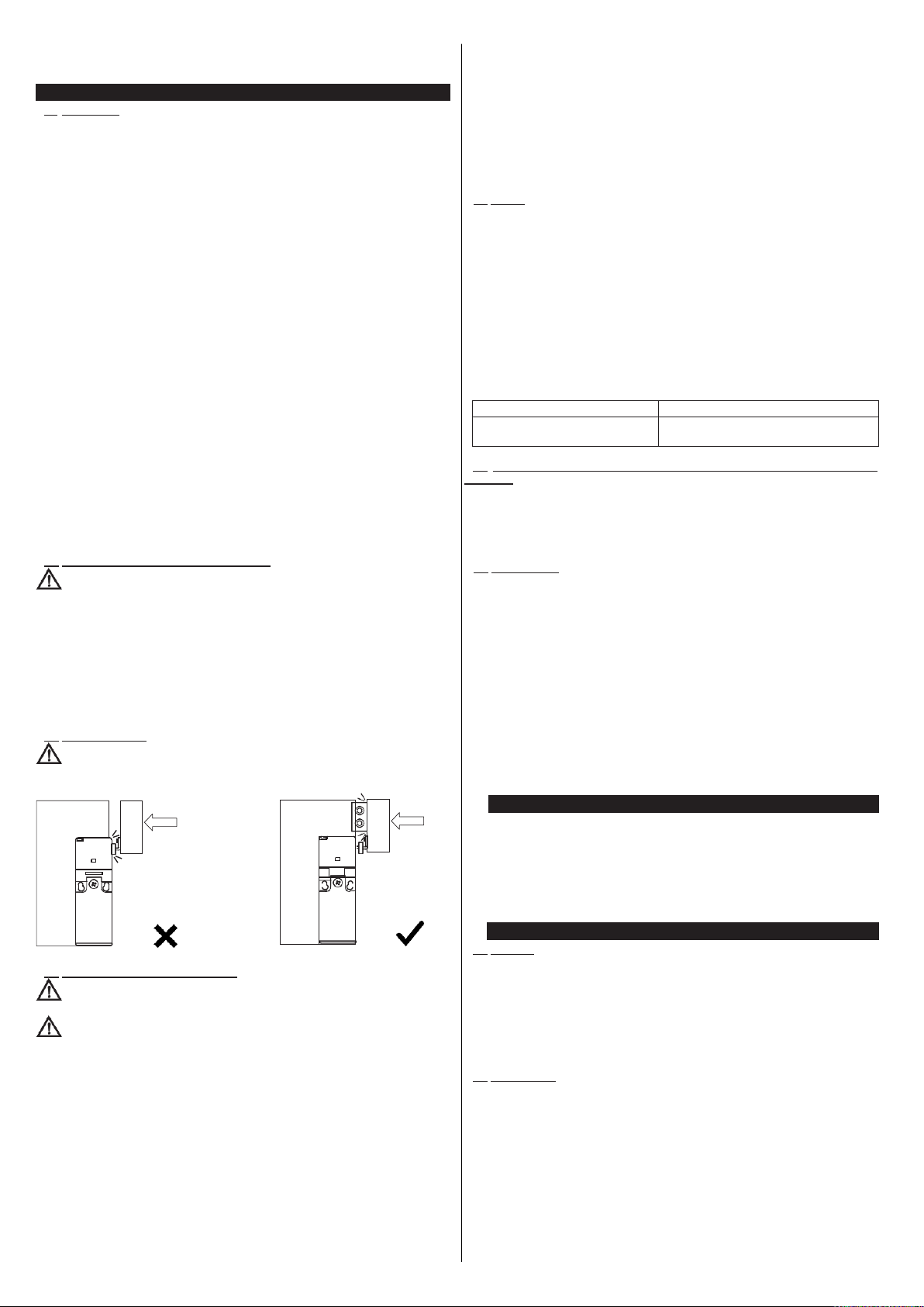
The actuator must be securely locked to the door; make sure that none of the
machine operator’s tools can be used to disconnect the actuator from the door.
7)
If you have difficulty inserting the actuator in the switch, never apply oil or grease
to the switch head; instead, check the actuator alignment as described in para-
graph INSTALLATION INSTRUCTIONS. If it is still difficult to insert the actuator,
replace the entire device.
8)
The device has been created for applications in dangerous environments, there-
fore it has a limited service life. Although still functioning, after 20 years from the
dateof manufacturethedevicemust bereplaced completely.The date of manufac-
ture is placed next to the product code (see paragraph MARKINGS).
6.5
Wiring
-
Keep the charge within the values specified in the electrical operation categories.
-
Only connect and disconnect the device when the power is off.
-
Always connect the protection fuse (or equivalent device) in series to the safety
electrical contacts.
-
At the end of the wiring, check that no contaminating element has been introduced
inside the device.
-
Before closing the device cover verify the correct positioning of the gaskets.
-
Verify that the electrical cables, wire-end sleeves, cable numbering systems and any
other parts do not obstruct thecover from closing correctly or if pressed between them
do not damage or compress internal parts.
-
During and after the installation do not pull the electrical cables connected to the
device. If traction is applied to the cables (not supported by an appropriate cable
gland) internal parts of the device may be damaged.
-
Adhere to the following minimum and maximum cross-sections of electrical
conductors designed for screw terminals:
Contact blocks 20, 21, 22, 33, 34
Contact blocks 5, 6, 7, 9, 11, 13, 14, 18, 37, 66
min 1 x 0.34 mm2 (1 x AWG 22)
max. 2 x 1.5 mm2 (2 x AWG 16)
min 1 x 0.5 mm2 (1 x AWG 20)
max. 2 x 2.5 mm2 (2 x AWG 14)
6.6
Additional prescriptions for safety applications with operator protection
functions
Provided that all previous requirements for the devices are fulfilled, for installations with
operator protection function additional requirements must be observed.
-
The utilization implies knowledge of and compliance with following standards: EN
60947-5-3, EN ISO 13849-1, EN 62061, EN 60204-1, EN ISO 14119,
EN ISO 12100.
6.7
Limits of use
-
Use the device following the instructions, complying with its operation limits and the
standards in force.
-
The devices have specific application limits (min. and max. ambient temperature,
mechanical endurance, IP protection degree, etc.) These limitations are met by the
device only if considered individually and not as combined with each other.
-
The manufacturer’s liability is to be excluded in the following cases:
1)
Use not conforming to the intended purpose;
2)
Failure to adhere to these instructions or regulations in force;
3)
Fitting operations not carried out by qualified and authorized personnel;
4)
Omission of functional tests.
-
For the cases listed below, before proceeding with the installation contact our techni-
cal assistance service (see paragraph SUPPORT):
a)
In nuclear power stations, trains, airplanes, cars, incinerators, medical devices or
any application where the safety of two or more persons depend on the correct opera-
tion of the device;
b)
Applications not contemplated in this instruction manual.
7
MARKINGS
The outside of the device is provided with external marking positioned in a visible place.
Marking includes:
-
Producer trademark
-
Product code
-
Batch number and date of manufacture. Example: A18 FR1-123456. The batch's first
letter refers to the month of manufacture (A=January, B=February, etc.). The second
and third letters refer to the year of manufacture (18 = 2018, 19 = 2019, etc…).
8
TECHNICAL DATA
8.1
Housing
housing made of glass fibre reinforced technopolymer, self-extinguishing, shock-proof
and with double insulation
FR series: one threaded conduit entry M20x1.5 (standard)
FK series: one threaded conduit entry M16x1.5 (standard)
FX series: two knock-out threaded conduit entries M20x1.5 (standard)
FW series: three knock-out threaded conduit entries M20x1.5 (standard)
Protection degree: IP67 acc. to EN 60529 with cable gland of equal or higher
protection degree.
8.2
General data
SIL (SIL CL): up to SIL 3 acc. to EN 62061
Performance Level (PL): Up to PL e acc. to EN ISO 13849-1
Mechanical interlock, coded: type 2 acc. to EN ISO 14119
Coding level: low acc. to EN ISO 14119
B10d safety parameters: 2,000,000 for NC contacts
Mission time: 20 years
Ambient temperature: -25°C … +80°C
Storage temperature: -40°C … +80°C
Max.actuation frequency: 3600 operating cycles/hour
Mechanical endurance: 1 million operating cycles
Max.actuation speed: 0.5 m/s
Min. actuation speed: 1 mm/s
Mounting position: any
Actuator extraction force: 10 N (standard), 30 N (-E3 versions)

Sheet:
Date:
:
15367-0-en-2.1.0
2017/12/26
FR 593
Article:
Description: Interruptor de seguridad con actuador separado
7/1
2
8.3
Electrical data
8.3.1
Versions without connector:
Thermal current (Ith): 10 A
Rated insulation voltage (Ui): 500 Vac 600Vdc
400 Vac 500 Vdc (contact blocks 20, 21,
22, 33, 34)
Rated impulse withstand voltage (Uimp): 6 kV
applications and possible connections of the device, the examples and diagrams given in the present
manual are to be considered as merely descriptive; the user is deemed responsible for checking that
the specific application of the device complies with current standards. This document is a translation
of the original instructions. In case of discrepancy between the present sheet and the original copy, the
Italian version shall prevail. The present manual may not be reproduced, in whole or in part, without
the prior written permission by Pizzato Elettrica.
© 2018 Copyright Pizzato Elettrica. All rights reserved

Sheet:
Date:
:
15367-0-en-2.1.0
2017/12/26
FR 593
Article:
Description: Interruptor de seguridad con actuador separado
8/1
4 kV (contact blocks 20, 21, 22, 33, 34) Conditional short circuit current: 1000
A acc. to EN 60947-5-1 Protection against short circuits: type aM fuse 10 A 500 V
Pollution degree: 3
Utilization categories:
Alternating current: AC15 (50÷60 hz)
Ue (V) 250 400 500
Ie (A) 6 4 1
Direct current: DC13
Ue (V) 24 125 250
Ie (A) 6 1.1 0.4
8.3.2
Versions with M12 connector, 4-pole: Thermal
current (Ith): 4 A
Rated insulation voltage (Ui): 250 Vac 300Vdc
Protection against short circuits: type gG fuse 4 A 500 V
Pollution degree: 3
Utilization categories:
Alternating current: AC15 (50÷60 hz)
Ue (V) 24 120 250
Ie (A) 4 4 4
Direct current: DC13
Ue (V) 24 125 250
Ie (A) 4 1.1 0.4
8.3.3
Versions with M12 connector, 8-pole: Thermal
current (Ith): 2 A
Rated insulation voltage (Ui): 30 Vac 36Vdc
Protection against short circuits: type gG fuse 2 A 500 V
Pollution degree: 3
Utilization categories:
Alternating current: AC15 (50÷60 hz) Ue (V) 24
Ie (A) 2
Direct current: DC13
Ue (V) 24
Ie (A) 2
8.4Compliance with standards
EN 60947-5-1, EN 60947-1, EN 60204-1, EN ISO 14119, EN ISO 12100, EN 60529,
BG-GSET-15, UL 508, CSA 22.2 No. 14.
8.5Compliance with directives
Machinery Directive 2006/42/EC, EMC Directive 2014/30/EU, RohS Directive
2011/65/EU.
9
SPECIAL VERSIONS ON REQUEST
Special versions of the device are available on request.
The special versions may differ substantially from the indications in this instruction sheet.
The installer must ensure that he has received written information from the support service
regarding installation and use of the special version requested.
10
DISPOSAL
At the end of service life product must be disposed of properly, according to the rules in force
in the country in which the disposal takes place.
11 SUPPORT
The device can be used for safeguarding people’s physical safety, therefore in case of any
doubt concerning installation or operation methods, always contact our technical support
service:
Pizzato Elettrica Srl
Via Torino, 1 - 36063 Marostica (VI) - ITALY
Telephone +39.0424.470.930
Fax +39.0424.470.955
E-mail tech@pizzato.com
www.pizzato.com
Our support service provides assistance in Italian and English.
12 EC CONFORMITY DECLARATION
I, the undersigned, as a representative of the following manufacturer:
Pizzato Elettrica Srl - Via Torino, 1 - 36063 Marostica (VI) –ITALY
hereby declare that the product is in conformity with whatever prescribed by the 2006/42/ EC
Machine Directive. The complete version of the present conformity declaration is available
on our website www.pizzato.com
Marco Pizzato
DISCLAIMER:
Subject to modifications without prior notice and errors excepted. The data given in this sheet are accurately

Sheet:
Date:
:
15367-0-en-2.1.0
2017/12/26
FR 593
Article:
Description: Interruptor de seguridad con actuador separado
9/1
checked and refer to typical mass production values. The device descriptions and its applications, the fields
of application, the external control details, as well as information on installation and operation, are provided to
the best of our knowledge. This does not in any way mean that the characteristics described may entail
legal liabilities extending beyond the “General Terms of Sale”, as stated in the Pizzato Elettrica general
catalogue. Customers/users are not absolved from the obligation to read and understand our information
and recommendations and pertinent technical standards, before using the products for their own purposes.
Taking into account the great variety of
This manual suits for next models
8
Table of contents
Other pizzato Switch manuals

pizzato
pizzato NG 2D1D411C-F31 User manual

pizzato
pizzato FD-M2-EX7 Series User manual

pizzato
pizzato FD EX7 Series User manual

pizzato
pizzato FD 93 Series User manual

pizzato
pizzato FD-EX4 Series User manual

pizzato
pizzato FD EX8 Series User manual

pizzato
pizzato HP AA Series User manual

pizzato
pizzato FD 874 User manual
Popular Switch manuals by other brands

Market Central
Market Central SwitchMaster R6000 Series manual

Fracarro
Fracarro SCD2-5416W operating instructions

ZyXEL Communications
ZyXEL Communications AES-100 user guide

Illumra
Illumra ZBT-S1AWH quick start guide

OSD NETWORKS
OSD NETWORKS OSD2254EP Operator's manual

GE
GE 3-Device HDMI Switch quick start guide