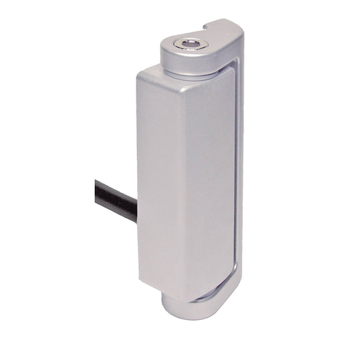
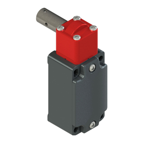
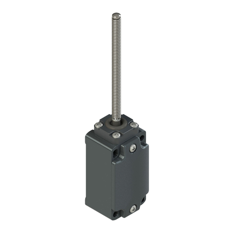
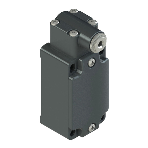
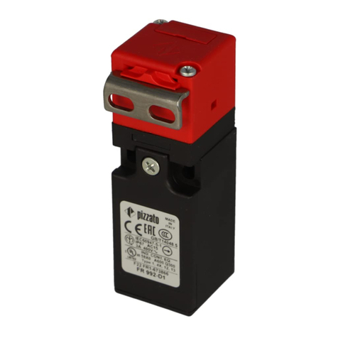
pizzato FD 93 Series User manual

1/12
Pizzato Elettrica srl
via Torino, 1
36063 MAROSTICA (VI)
ITALY
e-mail: [email protected]
web site: www.pizzato.com
Phone: +39.0424.470.930
ZE FOG128A19-EU
1 INFORMAZIONI SUL PRESENTE DOCUMENTO
1.1 Funzione
Il presente manuale di istruzioni fornisce informazioni su installazione, collegamento e
uso sicuro dei seguenti articoli: FD••93,FP••93,FL••93,FC••93,FD••R2,FP••R2,
FD••99,FP••99
1.2Achisirivolge
Le operazioni descritte nel presente manuale di istruzioni, devono essere eseguite
esclusivamente da personale qualificato, perfettamente in grado di comprenderle, con
le necessarie qualifiche tecnico professionali per intervenire sulle macchine e impianti
in cui saranno installati i dispositivi di sicurezza.
1.3Campodiapplicazione
Le presenti istruzioni si applicano esclusivamente ai prodotti elencati nel paragrafo
Funzione e ai loro accessori.
1.4Istruzionioriginali
La versione in lingua italiana rappresenta le istruzioni originali del dispositivo. Le
versioni disponibili nelle altre lingue sono una traduzione delle istruzioni originali.
2SIMBOLOGIAUTILIZZATA
Questo simbolo segnala valide informazioni supplementari.
Attenzione: Il mancato rispetto di questa nota di attenzione può causare rotture
o malfunzionamenti, con possibile perdita della funzione di sicurezza.
3DESCRIZIONE
3.1Descrizionedeldispositivo
I dispositivi di sicurezza descritti nel presente manuale sono definiti in accordo a EN
ISO 14119 come interblocchi meccanici, codificati, di tipo 2.
Gli interruttori di sicurezza ad azionatore separato a cui si riferiscono le presenti
istruzioni d’uso sono dispositivi di sicurezza progettati e realizzati per il controllo di
cancelli, protezioni, carter e ripari in genere, installati a protezione di parti pericolose
di macchine senza inerzia.
L’azionatore viene installato sulla parte mobile della protezione in modo che, ad ogni
apertura, venga estratto dall’interruttore.
Nei dispositivi FD ••99 e FP ••99 l’azionatore può essere estratto dall’interruttore
solo dopo una rotazione di 180° della chiave nella serratura presente sul corpo
dell’interruttore.
Nei dispositivi FD ••R2 e FP ••R2 l’azionatore può essere estratto dall’interruttore solo
dopo aver ruotato in senso orario fino a fondo corsa il pomello presente sul corpo
dell’interruttore.
3.2Usoprevistodeldispositivo
- Il dispositivo descritto nel presente manuale nasce per essere applicato su macchine
industriali per il controllo dello stato di protezioni mobili.
- È vietata la vendita diretta al pubblico di questo dispositivo. L’uso e l’installazione è
riservata a personale specializzato.
- Non è consentito utilizzare il dispositivo per usi diversi da quanto indicato nel
presente manuale.
- Ogni utilizzo non espressamente previsto nel presente manuale è da considerarsi
come utilizzo non previsto da parte del costruttore.
- Sono inoltre da considerare utilizzi non previsti:
a) utilizzo del dispositivo a cui siano state apportate modifiche strutturali, tecniche o
elettriche;
b) utilizzo del prodotto in un campo di applicazione diverso da quanto riportato nel
paragrafo CARATTERISTICHE TECNICHE.
4ISTRUZIONIDIMONTAGGIO
Attenzione: L’installazione di un dispositivo di protezione non è sufficiente a
garantire l’incolumità degli operatori e la conformità a norme o direttive specifiche
per la sicurezza delle macchine. Prima di installare un dispositivo di protezione è
necessario eseguire un’analisi del rischio specifica secondo i requisiti essenziali di
salute e sicurezza della Direttiva Macchine. Il costruttore garantisce esclusivamente
la sicurezza funzionale del prodotto a cui si riferisce il presente manuale di istruzioni,
non la sicurezza funzionale dell’intera macchina o dell’intero impianto.
4.1Sceltadeltipodiazionatore
L’interruttore è attivato da un azionatore a basso livello di codifica.Assicurarsi di usare
solamente l’azionatore fornito con l’interruttore oppure utilizzare uno dei seguenti
azionatori: VF KEYF, VF KEYF1, VF KEYF2, VF KEYF3, VF KEYF7, VF KEYF8.
Utilizzando qualsiasi altro azionatore la sicurezza del sistema non è garantita.
Attenzione: Eventuali altri azionatori presenti nello stesso luogo dove è stato
installato il dispositivo, devono essere segregati e tenuti sotto stretto controllo per
evitare l’elusione del dispositivo di sicurezza. Qualora vengano montati nuovi
azionatori, gli azionatori originali a basso livello di codifica, devono essere smaltiti
oppure resi inutilizzabili.
4.2Orientamentotestaedispositivodisblocco(dovepresente)
È possibile regolare la posizione della
testa e del dispositivo di sblocco (se
presente), con rotazioni di 90°, per
orientare il dispositivo nella posizione
più consona per l’applicazione a bordo
macchina.
Rimuovere le 2 viti sulla parte superiore
della testa e staccare la testa dal corpo
dell’interruttore.
Rimuovere le 4 viti di fissaggio del
dispositivo di sblocco ausiliario, ruotarlo
nella posizione desiderata e riavviare le
4 viti.
Posizionare la testa dell’interruttore
con l’orientamento desiderato sopra
il dispositivo di sblocco ausiliario e
ripristinare le 2 viti di fissaggio sui fori
predisposti.
Attenzione: serrare le viti della testa e del dispositivo di sblocco ausiliario con
una coppia compresa tra 0,8 a 1,2 Nm.
Sulla testa dell’interruttore sono predisposti due ingressi per l’azionatore, uno
perpendicolare e l’altro parallelo al corpo del dispositivo: una volta scelta la direzione
di ingresso per l’azionatore, è necessario sigillare il foro di ingresso inutilizzato con
l’apposito tappo in dotazione. È possibile utilizzare un solo foro di ingresso alla volta
con un solo azionatore.
4.3Fissaggiodeldispositivo
Attenzione: Il dispositivo deve essere sempre fissato con un numero di viti M5
pari al numero di fori presenti sulla custodia. Le viti devono avere classe di resistenza
8.8 o superiore e sotto testa piano. Le viti devono essere montate con frena filetti di
media resistenza e avere un numero di filetti in presa, uguale o superiore al proprio
diametro. Non è ammesso il fissaggio del dispositivo con un numero di viti inferiore al
numero di fori presenti nella custodia.
La coppia di serraggio delle viti M5 deve essere compresa tra 2 e 3 Nm
Si consiglia di installare il dispositivo nella parte alta della porta, in modo da
prevenire l’introduzione di sporco o residui di lavorazione all’interno del foro per
l’inserimento dell’azionatore.
4.4Fissaggiodell’azionatoreallaprotezione
Attenzione: Come prescritto dalla norma EN ISO 14119 l’azionatore deve
essere fissato al telaio della porta in modo inamovibile.
Installare l’azionatore in modo tale che l’estremità non sporga in modo pericoloso
nell’area di lavoro dell’operatore quando la porta è aperta.
L’azionatore deve essere sempre fissato con 2 viti M5 con classe di resistenza 8.8
o superiore e con sotto testa piano. Le viti devono essere montate con frena filetti di
media resistenza e avere un numero di filetti in presa, uguale o superiore al proprio
diametro. Non è ammesso il fissaggio dell’azionatore con un numero di viti inferiore a
2. La coppia di serraggio delle viti M5 deve essere compresa tra 1.2 e 1.6 Nm
Durante il fissaggio non deformare per nessun motivo l’azionatore.
Per un fissaggio corretto possono essere utilizzati anche altri mezzi come rivetti, viti di
sicurezza non smontabili (one-way) o altro sistema di fissaggio equivalente, purché in
grado di garantire un adeguato fissaggio.
4.5Allineamentointerruttore-azionatore
Prima della messa in servizio della
macchina e periodicamente, verificare
il corretto allineamento tra l’interrutto-
re e il suo azionatore. L’azionatore non
deve urtare la zona di imbocco sull’in-
terruttore e non deve essere utilizzato
come dispositivo di centraggio della
protezione mobile.
Per le regolazioni non utilizzare un
martello, svitare le viti e regolare ma-
nualmente il dispositivo per poi serrar-
lo in posizione.
4.6Collegamentielettrici
Attenzione: il circuito di sicurezza deve essere collegato ai contatti di sicurezza
(11-12, 21-22, 31-32). I contatti ausiliari (13-14, 23-24, 33-34) devono essere utilizzati
solo per segnalazione.
Per accedere ai morsetti dell’unità di contatto, aprire il coperchio sulla parte frontale
dell’interruttore, rimuovendo le viti di fissaggio,
Al termine delle operazioni di cablaggio richiudere sempre il coperchio facendo
attenzione che la guarnizione di tenuta sia alloggiata nella propria sede.
5 FUNZIONAMENTO
Quando il dispositivo è stato fissato alla macchina e alla protezione apribile, nonché
collegato elettricamente, secondo le modalità descritte nel paragrafo “ISTRUZIONI DI
MONTAGGIO”, l’estrazione o lo sblocco dell’azionatore dall’interruttore deve causare
l’arresto della macchina e dei relativi organi mobili pericolosi.
Il successivo riavvio della macchina dovrà essere possibile soltanto dopo aver
nuovamente inserito e bloccato (se è presente il meccanismo di blocco) l’azionatore

2/12
nel dispositivo.
5.1Controlloaccessi
Questo interruttore da solo non è in grado di proteggere operatori o manutentori nel
caso essi possano fisicamente entrare con tutto il corpo nella zona di pericolo, in
quanto un’involontaria chiusura della protezione alle loro spalle, potrebbe permettere
il riavvio della macchina. Nel caso l’autorizzazione al riavvio della macchina sia
interamente affidata a questo dispositivo, devono essere previsti sistemi di protezione
aggiuntivi (Lock out/Tag out) per evitare questo rischio, utilizzando ad esempio il
dispositivo lucchettabile di blocco dell’ingresso dell’azionatore (articolo VF KB1),
appositamente studiato in modo da prevenire qualsiasi avvio imprevisto della
macchina con l’operatore ancora al suo interno.
Per maggiori informazioni contattate l’assistenza tecnica (vedi paragrafo SUPPORTO).
5.2Utilizzodellosbloccoconserratura
Gli articoli FD ••99, FP ••99 sono dotati di sblocco con serratura per permettere
l’apertura del riparo solamente al personale autorizzato con l’apposita chiave in
dotazione. Questo dispositivo meccanico agisce direttamente sul
meccanismo di blocco, rilasciando l’azionatore indipen-
dentemente dalle condizioni in cui si trova il dispositivo.
Solo il manutentore della macchina adeguatamente for-
mato sui pericoli derivanti dal suo utilizzo è autorizzato
ad azionare questo dispositivo di sblocco.
Procedura di utilizzo dello sblocco ausiliario a serratura:
1) Aprire il cappuccio di protezione.
2) Inserire la chiave fornita in dotazione con l’interruttore
e ruotare in senso orario di 180°.
3) Non forzare la chiave oltre i 180°.
4) Estrarre l’azionatore dal dispositivo.
5) Con l’azionatore estratto non ruotare la chiave.
6) Ogni qual volta la chiave venga estratta, chiudere il
cappuccio in gomma.
Attenzione:
- La chiave di sblocco deve essere a disposizione del solo manutentore della macchi-
na e conservata in luogo segregato.
- La chiave di sblocco non deve essere a disposizione dell’operatore della macchina.
- La chiave di sblocco non deve essere lasciata inserita nel dispositivo durante il nor-
male utilizzo della macchina.
5.3Utilizzodellosbloccoconritardomeccanicomanuale
Gli articoli FD ••R2, FP ••R2 sono dotati di sblocco con ritardo meccanico manuale per
utilizzo dove la condizione di pericolo si protrae entro un tempo limitato anche dopo
aver azionato il comando di arresto della macchina.
Questo dispositivo meccanico agisce direttamente sul
meccanismo di blocco, rilasciando l’azionatore indipen-
dentemente dalle condizioni in cui si trova il dispositivo.
Procedura di utilizzo dello sblocco ausiliario con ritardo
meccanico manuale:
1) Per sbloccare l’azionatore ruotare il pomello in senso
orario fino al suo arresto a fondo corsa, solo successiva-
mente estrarre l’azionatore.
2) Per bloccare l’azionatore inserire lo stesso nel dispo-
sitivo e solo successivamente ruotare il pomello in senso
antiorario fino al suo arresto a fondo corsa.
3) Non forzare il pomello ruotandolo in senso antiorario ad
azionatore disinserito.
6 AVVERTENZE PER UN CORRETTO USO
6.1 Installazione
- Serrare le viti di fissaggio dei conduttori elettrici con una coppia compresa tra 0,6
e 0,8 Nm.
- Non sollecitare il dispositivo con flessioni o torsioni.
- Non modificare il dispositivo per nessun motivo.
- Non superare le coppie di serraggio indicate nel presente manuale.
- Il dispositivo svolge una funzione di protezione degli operatori. L’installazione inade-
guata o le manomissioni possono causare gravi lesioni alle persone fino alla morte,
danni alle cose e perdite economiche.
- Questi dispositivi non devono essere né aggirati, né rimossi, né ruotati o resi ineffi-
caci in altra maniera.
- Se la macchina dove il dispositivo è installato viene utilizzata per un uso diverso da
quello specificato, il dispositivo potrebbe non fornire una protezione efficace per
l’operatore.
- La categoria di sicurezza del sistema (secondo EN ISO 13849-1) comprendente il
dispositivo di sicurezza, dipende anche dai componenti esterni ad esso collegati e
dalla loro tipologia.
- Prima dell’installazione assicurarsi che il dispositivo sia integro in ogni sua parte.
- Evitare piegature eccessive dei cavi di connessione per impedire cortocircuiti e in-
terruzioni.
- Non verniciare o dipingere il dispositivo.
- Non forare il dispositivo.
- Non utilizzare il dispositivo come supporto o appoggio per altre strutture come cana-
line, guide di scorrimento o altro.
- Prima della messa in funzione, assicurarsi che l’intera macchina (o il sistema) sia
conforme alle norme applicabili e ai requisiti della direttiva Compatibilità Elettroma-
gnetica.
- La superficie di montaggio del dispositivo deve essere sempre piana e pulita.
- La documentazione necessaria per una corretta installazione e manutenzione è
sempre disponibile nelle seguenti lingue: inglese, francese, tedesco, italiano.
- Nel caso l’installatore non sia in grado di comprendere pienamente la documentazio-
ne, non deve procedere con l’installazione del prodotto e può chiedere assistenza
(vedi paragrafo SUPPORTO).
- Quando il dispositivo viene installato su un telaio mobile e l’azionatore viene instal-
lato su una porta mobile anch’essa, verificare che il dispositivo non venga danneg-
giato da un’apertura contemporanea del telaio e della porta.
- Allegare sempre le presenti prescrizioni d’impiego nel manuale della macchina in cui
il dispositivo è installato.
- La conservazione delle presenti prescrizioni d’impiego deve permettere la loro con-
sultazione per tutto il periodo di utilizzo del dispositivo.
6.2Nonutilizzareneiseguentiambienti
Attenzione: Non utilizzare in ambienti dove polvere e sporcizia possono in
qualsiasi modo penetrare nella testa e sedimentare. In modo particolare non utilizzare
in ambienti dove è spruzzata polvere metallica, cemento o prodotti chimici.
- In ambienti dove continui sbalzi di temperatura provocano formazione di condensa
all’interno del dispositivo.
- In ambienti dove l’applicazione provoca collisioni, urti o forti vibrazioni al dispositivo.
- In ambienti con presenza di polveri o gas esplosivi o infiammabili. La presente limita-
zione non si applica ai dispositivi dichiarati conformi alla direttiva ATEX 2014/34/UE.
- In ambienti dove è possibile la formazione di manicotti di ghiaccio sul dispositivo.
- In ambienti fortemente chimico aggressivi, dove i prodotti utilizzati che vengono a
contatto con il dispositivo, possono comprometterne l’integrità fisica o funzionale.
6.3Arrestomeccanico
Attenzione: La porta deve essere sempre dotata di un arresto meccanico
indipendente in chiusura a fondo corsa.
Non utilizzare il dispositivo come arresto meccanico della porta.
6.4Manutenzioneeprovefunzionali
Attenzione: Non smontare o tentare di riparare il dispositivo. In caso di anomalia
o guasto sostituire l’intero dispositivo.
Attenzione: In caso di danneggiamenti o di usura si deve sostituire il dispositivo
completo e anche il suo azionatore. Con il dispositivo deformato o danneggiato il
funzionamento non è garantito.
- È responsabilità dell’installatore stabilire la sequenza di prove funzionali a cui sot-
toporre il dispositivo prima della messa in funzione della macchina e durante gli
intervalli di manutenzione.
- La sequenza delle prove funzionali può variare in base alla complessità della mac-
china e dal suo schema circuitale, pertanto la sequenza di prove funzionali sotto
riportata è da considerarsi minimale e non esaustiva.
- Eseguire prima della messa in funzione della macchina e almeno una volta all’anno
(o dopo un arresto prolungato) la seguente sequenza di verifiche:
1) Per gli articoli FD ••93, FP ••93, FL ••93, FC ••93:
- Aprire la protezione con la macchina in movimento. La macchina si deve arrestare
immediatamente. Il tempo di arresto della macchina dovrà essere sempre inferiore
al tempo impiegato dall’operatore per aprire la protezione e raggiungere gli elementi
pericolosi.
Per gli articoli FD ••99, FP ••99:
- Bloccare la protezione ed avviare la macchina. Dovrà risultare impossibile aprire
la protezione.
- Sbloccare la protezione con l’apposita chiave. La macchina si deve arrestare im-
mediatamente. Il tempo di arresto della macchina dovrà essere sempre inferiore al
tempo impiegato dall’operatore per aprire la protezione e raggiungere gli elementi
pericolosi.
Per gli articoli FD ••R2, FP ••R2:
- Bloccare la protezione ed avviare la macchina. Dovrà risultare impossibile aprire
la protezione.
- Iniziare a ruotare in senso orario il pomello di sblocco. Sin dai primi giri la macchina
deve iniziare a fermarsi. La macchina deve arrestarsi completamente prima che la
porta venga sbloccata dalla rotazione in senso orario del pomello. Il tempo di arresto
della macchina dovrà essere sempre inferiore al tempo impiegato dall’operatore per
aprire la protezione e raggiungere gli elementi pericolosi.
2) Con la protezione aperta tentare di avviare la macchina. La macchina non deve
avviarsi.
3) Verificare il corretto allineamento tra azionatore e dispositivo. Se l’imbocco dell’a-
zionatore risulta usurato, sostituire tutto il dispositivo e il suo azionatore.
4) L’insieme delle parti esterne non deve essere danneggiato.
5) Se il dispositivo è danneggiato, sostituirlo completamente.
6) L’azionatore deve essere saldamente bloccato alla porta, verificare che non sia
possibile con utensili in uso all’operatore della macchina, scollegare l’azionatore
dalla porta.
7) In caso di difficoltà nell’inserimento dell’azionatore nell’interruttore, non introdurre
olio o grasso nella testa dell’interruttore, ma verificare l’allineamento dell’azionato-
re come descritto nel paragrafo ISTRUZIONI DI MONTAGGIO. Qualora l’ingresso
dell’azionatore continuasse a essere difficoltoso, sostituire l’intero dispositivo.
8) Il dispositivo nasce per applicazioni in ambienti pericolosi, pertanto il suo utilizzo è
limitato nel tempo. Trascorsi 20 anni dalla data di produzione, il dispositivo deve es-
sere sostituito completamente, anche se ancora funzionante. La data di produzione
è posta vicino al codice prodotto (vedi paragrafo MARCATURE).
6.5Cablaggio
Attenzione: Verificare che la tensione di alimentazione sia corretta prima di
alimentare il dispositivo.
- Mantenere il carico all’interno dei valori indicati nelle categorie d’impiego elettriche.
- Collegare e scollegare il dispositivo solamente in assenza di tensione.
- Durante e dopo l’installazione non tirare i cavi elettrici collegati al dispositivo.
- Collegare sempre il fusibile di protezione (o un dispositivo equivalente) in serie ai
contatti elettrici di sicurezza.
- Al termine del cablaggio, verificare che nessun elemento contaminante sia stato
introdotto all’interno del dispositivo.
- Prima di chiudere il coperchio del dispositivo verificare il corretto posizionamento
delle guarnizioni di tenuta.
- Verificare che i cavi elettrici, puntalini, sistemi di numerazione dei cavi o altre parti
non impediscano una corretta chiusura del coperchio o che, schiacciandosi tra loro,

3/12
non possano danneggiare o comprimere le sue parti interne
- Durante e dopo l’installazione non tirare i cavi elettrici collegati al dispositivo. Nel caso
venissero applicate forze di trazione ai cavi elettrici (non supportate da un adeguato
pressacavo) le parti interne del dispositivo potrebbero danneggiarsi.
- Rispettare le seguenti sezioni minime e massime dei conduttori elettrici previste per
i morsetti a vite:
Unitàdicontatto20,21,22,28,29,30,33,34 Unitàdicontatto5,6,7,9,18
min 1 x 0,34 mm2(1 x AWG 22)
max 2 x 1,5 mm2(2 x AWG 16) min 1 x 0,5 mm2(1 x AWG 20)
max 2 x 2,5 mm2(2 x AWG 14)
- La lunghezza di spellatura del cavo o del puntalino (x) deve essere pari a 7 mm (per
unità di contatto 20, 21, 22, 28, 29, 30, 33, 34) o 8 mm (per unità di contatto 5, 6, 7,
9, 18).
xx
6.6 Prescrizioni aggiuntive per applicazioni di sicurezza con funzioni di
protezionedellepersone
Fermo restando tutte le precedenti prescrizioni, nel caso in cui i dispositivi vengano
installati con funzione di protezione delle persone, vanno rispettate le seguenti
prescrizioni aggiuntive.
- L’impiego implica il rispetto e la conoscenza delle norme EN 60947-5-3,
EN ISO 13849-1, EN 62061, EN 60204-1, EN ISO 14119, EN ISO 12100.
6.7Limitidiutilizzo
- Utilizzare il dispositivo seguendo le istruzioni, attenendosi ai suoi limiti di funziona-
mento e impiegandolo secondo le norme di sicurezza vigenti.
- I dispositivi hanno dei specifici limiti di applicazione (temperatura ambiente minima
e massima, durata meccanica, grado di protezione IP, ecc.) Questi limiti vengono
soddisfatti dal dispositivo solo se presi singolarmente e non in combinazione tra loro.
- La responsabilità del costruttore è esclusa in caso di:
1) impiego non conforme alla destinazione;
2) mancato rispetto delle presenti istruzioni o delle normative vigenti;
3) montaggio non eseguito da persone specializzate e autorizzate;
4) omissione delle prove funzionali.
- Nei casi di applicazione sotto elencati, prima di procedere con l’installazione, contat-
tare l’assistenza tecnica (vedi paragrafo SUPPORTO):
a) in centrali nucleari, treni, aeroplani, automobili, inceneritori, dispositivi medici o
comunque in applicazioni nelle quali la sicurezza di due o più persone dipenda dal
corretto funzionamento del dispositivo;
b) casi non citati nel presente manuale.
7MARCATURE
Il dispositivo è provvisto di marcatura posizionata all’esterno in maniera visibile. La
marcatura include:
- marchio del produttore
- codice del prodotto
- numero di lotto e data di produzione. Esempio: A19 FD1-123456. La prima lettera del
lotto indica il mese di produzione (A = gennaio, B = febbraio, ecc.). La seconda e terza
cifra indicano l’anno di produzione (19 = 2019, 20 = 2020, ecc.).
8CARATTERISTICHETECNICHE
8.1Custodia
Serie FP: Custodia in tecnopolimero rinforzato fibra di vetro autoestin-
guente e antiurto a doppio isolamento
1 entrata cavi filettata M20x1,5 (standard)
Serie FD, FC: Custodia in metallo, verniciata a polvere cotta in forno
1 entrata cavi filettata M20x1,5 (standard)
Serie FL: Custodia in metallo, verniciata a polvere cotta in forno
3 entrate cavi filettate M20x1,5 (standard)
Testa: In metallo,
verniciata a polvere cotta in forno
Grado di protezione: IP67 secondo EN 60529
con pressacavo avente grado di protezione uguale o superiore
8.2Generali
Interblocco con blocco meccanico, codificato: tipo 2 secondo EN ISO 14119
Livello di codifica: basso secondo EN ISO 14119
SIL (SIL CL): fino a SIL 3 secondo EN 62061
Performance level (PL): fino a PL e secondo EN ISO 13849-1
Parametri di sicurezza:
B10d (articoli FD ••93, FL ••93, FP ••93, FC ••93): 2.000.000 per contatti NC
B10d (articoli FD ••R2, FP ••R2, FD ••99, FP ••99): 1.000.000 per contatti NC
Mission time: 20 anni
Temperatura ambiente: da -25°C a +80°C
Temperatura di stoccaggio: da -40°C a +80°C
Frequenza massima di azionamento: 3600 cicli di operazioni/ora
Durata meccanica: 1 milione di cicli di operazioni
Velocità massima di azionamento: 0,5 m/s
Velocità minima di azionamento: 1 mm/s
Posizione di montaggio: qualsiasi
Forza di estrazione dell’azionatore sbloccato: max 30 N
Forza massima prima della rottura F1max (articoli FD ••R2, FP ••R2, FD ••99, FP ••99):
1000 N secondo EN ISO 14119
Forza di ritenuta massima FZh (articoli FD ••R2, FP ••R2, FD ••99, FP ••99):
770 N secondo EN ISO 14119
8.3Caratteristicheelettriche
8.3.1 Versioni senza connettore:
Corrente termica (Ith): 10 A
Tensione nominale di isolamento (Ui): 500 Vac 600 Vdc
400 Vac 500 Vdc
(unità di contatto 20,21,22,28,29,30,33,34)
Tensione di tenuta ad impulso nominale (Uimp): 6 kV
4kV
(unità di contatto 20,21,22,28,29,30,33,34)
Corrente di corto circuito condizionata: 1000 A secondo EN 60947-5-1
Protezione dai cortocircuiti: fusibile 10 A 500 V tipo aM
Grado di inquinamento: 3
Categorie d’impiego:
Corrente alternata: AC15 (50÷60 Hz)
Ue(V) 250 400 500
Ie(A) 6 4 1
Corrente continua: DC13
Ue(V) 24 125 250
Ie(A) 3 0,55 0,3
8.3.2 Versioni con connettore M12 a 4 o 5 poli:
Corrente termica (Ith): 4 A
Tensione nominale di isolamento (Ui): 250 Vac 300 Vdc
Protezione dai cortocircuiti: fusibile 4 A 500 V tipo gG
Grado di inquinamento: 3
Categorie d’impiego:
Corrente alternata: AC15 (50÷60 Hz)
Ue(V) 24 120 250
Ie(A) 4 4 4
Corrente continua: DC13
Ue(V) 24 125 250
Ie(A) 3 0,55 0,3
8.3.3 Versioni con connettore M12 a 8 poli:
Corrente termica (Ith): 2 A
Tensione nominale di isolamento (Ui): 30 Vac 36 Vdc
Protezione dai cortocircuiti: fusibile 2 A 500 V tipo gG
Grado di inquinamento: 3
Categorie d’impiego:
Corrente alternata: AC15 (50÷60 Hz)
Ue(V) 24
Ie(A) 2
Corrente continua: DC13
Ue(V) 24
Ie(A) 2
8.4Conformitàallenorme
EN 60947-5-1, EN 60947-1, EN 60204-1, EN ISO 14119, EN ISO 12100, EN 60529,
BG-GSET-15, UL 508, CSA 22.2 N. 14.
8.5Conformitàalledirettive
Direttiva Macchine 2006/42/CE, Direttiva Compatibilità Elettromagnetica 2014/30/UE,
Direttiva RoHS 2011/65/UE.
9VERSIONISPECIALIARICHIESTA
Sono disponibili versioni speciali a richiesta del dispositivo.
Le versioni speciali possono differire anche sostanzialmente da quanto indicato nel
presente foglio di istruzioni.
L’installatore deve assicurarsi di aver ricevuto dal servizio di supporto informazioni
scritte in merito a installazione e utilizzo della versione speciale richiesta.
10SMALTIMENTO
Il prodotto deve essere smaltito correttamente a fine vita, in base alle regole vigenti nel
paese in cui lo smaltimento avviene.
11 SUPPORTO
Il dispositivo può essere utilizzato per la salvaguardia dell’incolumità fisica delle
persone, pertanto in qualsiasi caso di dubbio sulle modalità di installazione o utilizzo,
contattare sempre il nostro supporto tecnico:
Pizzato Elettrica Srl
Via Torino, 1 - 36063 Marostica (VI) - ITALY
Telefono +39.0424.470.930
E-mail tech@pizzato.com
www.pizzato.com
Il nostro supporto fornisce assistenza nelle lingue italiano e inglese.
12DICHIARAZIONECEDICONFORMITÀ
Il sottoscritto, rappresentante il seguente costruttore:
Pizzato Elettrica Srl - Via Torino, 1 - 36063 Marostica (VI) – ITALY
dichiara qui di seguito che il prodotto risulta in conformità con quanto previsto dalla
Direttiva macchine 2006/42/CE.La versione completa della dichiarazione di conformità
è disponibile su sito www.pizzato.com
Pizzato Marco
DISCLAIMER:
Con riserva di modifiche senza preavviso e salvo errori. I dati riportati in questo foglio sono accurata-
mente controllati e rappresentano tipici valori della produzione in serie.Le descrizioni del dispositivo e
le sue applicazioni, i contesti di impiego, i dettagli su controlli esterni, le informazioni sull’installazione
e il funzionamento sono forniti al meglio delle nostre conoscenze.Ad ogni modo ciò non significa che
dalle caratteristiche descritte possano derivare responsabilità legali che si estendano oltre le “Condizioni
Generali di Vendita” come dichiarato nel catalogo generale di Pizzato Elettrica. Il cliente/utente non
è assolto dall’obbligo di esaminare le nostre informazioni e raccomandazioni e le normative tecniche
pertinenti prima di usare i prodotti per i propri scopi. Considerate le molteplici diverse applicazioni e
possibili collegamenti del dispositivo, gli esempi e i diagrammi riportati in questo manuale, sono da
considerarsi puramente descrittivi, è responsabilità dell’utilizzatore verificare che l’applicazione del
dispositivo sia conforme alla normativa vigente. Qualsiasi riproduzione anche parziale del presente
manuale, senza il permesso scritto di Pizzato Elettrica, è vietata.
© 2019 Copyright Pizzato Elettrica. Tutti i diritti riservati.

4/12
Pizzato Elettrica srl
via Torino, 1
36063 MAROSTICA (VI)
ITALY
e-mail: [email protected]
web site: www.pizzato.com
Phone: +39.0424.470.930
ZE FOG128A19-EU
1INFORMATIONONTHISDOCUMENT
1.1 Function
The present instruction manual provides information on installation, connection
and safe use for the following articles: FD••93,FP••93,FL••93,FC••93,FD••R2,
FP••R2,FD••99,FP••99
1.2Targetaudience
The operations described in this instruction manual must be carried out by qualified
personnel only, who are fully capable of understanding them, and with the technical
qualifications required for operating the machines and plants in which the safety de-
vices are to be installed.
1.3Applicationeld
These instructions apply exclusively to the products listed in paragraph Function, and
their accessories.
1.4Originalinstructions
The Italian language version is the original set of instructions for the device. Versions
provided in other languages are translations of the original instructions.
2SYMBOLSUSED
This symbol indicates any relevant additional information.
Attention: Any failure to observe this warning note can cause damage or mal-
function, including possible loss of the safety function.
3DESCRIPTION
3.1Devicedescription
The safety devices described in this manual are defined as coded, type 2 mechanical
interlocking devices acc. to EN ISO 14119.
The safety switches with separate actuator to which these usage instructions refer are
safety devices designed and implemented for the control of gates, guards, enclosures,
and doors in general, which are installed to protect dangerous parts of machines
without inertia.
The actuator is installed on the moving part of the guard in such a way that it is
extracted from the switch each time the guard is opened.
In FD ••99 and FP ••99 devices, the actuator can be extracted from the switch only
after rotating the key in the lock (on the switch body) 180°.
In FD ••R2 and FP ••R2 devices, the actuator can be extracted from the switch only
after rotating the knob on the switch body clockwise up to the stop.
3.2Intendeduseofthedevice
- The device described in this manual is designed to be applied on industrial machines
for state monitoring of movable guards.
- The direct sale of this device to the public is prohibited. Installation and use must be
carried out by qualified personnel only.
- The use of the device for purposes other than those specified in this manual is
prohibited.
- Any use other than as expressly specified in this manual shall be considered
unintended by the manufacturer.
- Also considered unintended use:
a) using the device after having made structural, technical, or electrical modifications
to it;
b) using the product in a field of application other than as described in paragraph
TECHNICAL DATA.
4 INSTALLATION INSTRUCTIONS
Attention: Installing a protective device is not sufficient to ensure operator safety
or compliance with machine safety standards or directives. Before installing a protec-
tive device, perform a specific risk analysis in accordance with the key health and
safety requirements in the Machinery Directive. The manufacturer guarantees only
the safe functioning of the product to which this instruction manual refers, and not the
functional safety of the entire machine or entire plant.
4.1Selectionoftheactuatortype
The switch is activated by a low level coded actuator. Please make sure to use only
the actuator provided with the switch or use one of the following actuators: VF KEYF,
VF KEYF1, VF KEYF2, VF KEYF3, VF KEYF7, VF KEYF8.
The use of any other actuator does not guarantee the safety of the system.
Attention: Any other actuators present in the same place where the device has
been installed must be segregated and kept under strict control in order to avoid any
bypassing of the safety device. If new actuators are fitted, the original low-level coding
actuators must be disposed of or rendered inoperable.
4.2Headandreleasedevice(wherepresent)orientation
If necessary, it is possible to adjust the
position of the head and the release
device (if present), in 90° rotations, at
the machine, in order to turn the device
to the position best suited to the
application.
Remove the 2 screws on the top of the
head, and disconnect the head from the
switch body.
Remove the 4 fixing screws from the
auxiliary release device; rotate it to the
desired position, and retighten the 4
screws.
Position the switch head, with the
desired orientation, above the auxiliary
release design device, and replace the
2 fixing screws on the holes provided.
Attention: tighten the head and auxiliary release device screws to a torque from
0.8 to 1.2 Nm.
The switch head has two actuator inputs: one perpendicular, and the other parallel
to the device body. Once the actuator input direction has been selected, the unused
input hole must be sealed, using the appropriate cap supplied. It is possible to use one
single hole at a time, with one single actuator.
4.3Fixingofthedevice
Attention: Always affix the device with a number of M5 screws equal to the
number of holes on the housing. Always use screws with a resistance class of 8.8 or
higher, and flat seating heads. Install the screws with medium resistance thread lock,
and a number of threads engaged equal to or greater than the screw diameter. The
device must never be fixed with fewer screws than holes available on the housing.
The tightening torque of the M5 screws must be between 2 and 3 Nm
It is advisable to install the device in the top part of the door, in order to prevent
any dirt or work residues from getting inside the hole where the actuator is to be
introduced.
4.4Fixingtheactuatortotheguard
Attention: As required by EN ISO 14119, the actuator must be fixed immovably
to the door frame.
Install the actuator so that its edge does not protrude dangerously into the
operator working area when the door is open.
Always affix the actuator with 2 M5 screws with resistance class 8.8 or higher, and flat
seating heads. Install the screws with medium resistance thread lock, and a number
of threads engaged equal to or greater than the screw diameter. The actuator must
never be fixed with fewer than 2 screws. Tighten the M5 screws to a torque from 1.2
to 1.6 Nm
Do not deform or modify the actuator during installation for any reason.
For correct fixing, other means can also be used, such as rivets, non-removable
security screws (one-way), or other equivalent fixing system, provided that it can
ensure adequate fixing.
4.5Switch-actuatoralignment
Before commissioning the machine,
and periodically, check that the align-
ment between switch and its actuator
is correct. The actuator must not im-
pact the inlet area on the switch, and
must not be used as a centring device
for the mobile guard.
Do not use a hammer for the adjust-
ments, unscrew the screws and adjust
the device manually, then tighten it in
position.
4.6Electricalconnections
Attention: the safety circuit must be connected to the safety contacts (11-12, 21-
22, 31-32). The auxiliary contacts (13-14, 23-24, 33-34) must be used for signalling
only.
To gain access to the contact block terminals, open the cover on the front switch part,
removing the fixing screws.
Once cabling work is complete, always re-close the cover; making sure that the seal
gasket is correctly inserted in its seat.
5 OPERATION
Once the device is installed on the machine and opening guard, and electrically
connected (as described in paragraph "INSTALLATION INSTRUCTIONS"), extracting
or releasing the switch actuator must initiate a stop of the machine and related
dangerous moving elements.
Subsequent machine restart shall be possible only once the actuator has been
reinserted to and blocked in the device (where the release mechanism is present).

5/12
5.1Accessmonitoring
This switch alone is not sufficient to protect any operators or maintenance engineers
in the event that they are able to physically enter the danger area with their whole
body, since any unintentional closing of a guard behind them could allow the machine
to be restarted. If this device is solely responsible for authorising machine re-start,
additional protection systems must be provided (lock out/tag out) to mitigate risk; using
for example the padlockable lock device to block the actuator input (item VF KB1),
designed specifically for prevention of any unexpected unintentional machine start-up
with the operator still inside it.
Please contact technical assistance for more information (see SUPPORT paragraph).
5.2Usingthereleasewithlock
Items FD ••99 and FP ••99 are equipped with a release with lock, to allow the guard to
be opened only by authorized personnel in possession of the appropriate key.
This mechanical device acts directly on the lock mecha-
nism, and releases the actuator regardless of device
state.
This release device may only be operated by a machine
maintenance engineer who has received adequate train-
ing on the dangers deriving from its use.
How to use the auxiliary key release:
1) Open the protection cap.
2) Insert the key supplied with the switch and turn clock-
wise by 180°.
3) Do not force the key beyond 180°.
4) Extract the actuator from the device.
5) Do not turn the key with the actuator extracted.
6) Each time after the key is extracted, close the rubber
cap.
Attention:- The release key must only be available to the machine maintenance
engineer and kept in a secluded place.
- The release key must not be available to the machine operator.
- Never leave the release key inserted in the device during normal machine operation.
5.3Usingthereleasewithmanualmechanicaldelay
Items FD ••R2 and FP ••R2 are equipped with a release with manual mechanical
delay, for use where the hazardous condition persists for a limited period, even after
the machine stop command has been actuated.
This mechanical device acts directly on the lock mecha-
nism, and releases the actuator regardless of device
state.
How to use the auxiliary release with manual mechanical
delay:
1) To release the actuator, rotate the knob clockwise as far
as it will go up to the stop; only then extract the actuator.
2) To lock the actuator, insert it in the device; only then,
rotate the knob anticlockwise as far as it will go up to the
stop.
3) Never force the knob, by turning it anticlockwise with
the actuator extracted.
6 INSTRUCTIONS FOR PROPER USE
6.1 Installation
- Tighten the fixing screws of electrical conductors to a torque from 0.6 to 0.8 Nm.
- Do not stress the device with bending and torsion.
- Do not modify the device for any reason.
- Do not exceed the tightening torques specified in the present manual.
- The device carries out an operator protection function. Any inadequate installation
or tampering can cause serious injuries and even death, property damage, and
economic losses.
- These devices must not be bypassed, removed, turned or disabled in any other way.
- If the machine where the device is installed is used for a purpose other than that
specified, the device may not provide the operator with efficient protection.
- The safety category of the system (according to EN ISO 13849-1), including the safe-
ty device, also depends on the external components connected to it and their type.
- Before installation, make sure the device is not damaged in any part.
- Avoid excessive bending of connection cables in order to prevent any short circuits
or power failures.
- Do not paint or varnish the device.
- Do not drill the device.
- Do not use the device as a support or rest for other structures, such as raceways,
sliding guides or similar.
- Before commissioning, make sure that the entire machine (or system) complies with
all applicable standards and EMC directive requirements.
- The fitting surface of the device must always be smooth and clean.
- The documents necessary for a correct installation and maintenance are always
available in the following languages: English, French, German and Italian.
- Should the installer be unable to fully understand the documents, the product must
not be installed and the necessary assistance may be requested (see paragraph
SUPPORT).
- When the device is installed on a mobile frame and the actuator is installed on a
mobile door, ensure that the device cannot be damaged by simultaneous opening
of the frame and the door.
- Always attach the following instructions to the manual of the machine in which the
device is installed.
- These operating instructions must be kept available for consultation at any time and
for the whole period of use of the device.
6.2Donotuseinthefollowingenvironments
Attention: Do not use in environments where dust and dirt may in any way
penetrate the head and deposit there. Do not use in particular where metal dust,
concrete or chemicals are spread.
- In environments where continual changes in temperature cause the formation of
condensation inside the device.
- In environments where the application causes collisions, impacts or strong vibrations
to the device.
- In environments with the presence of explosive or flammable dusts or gases.
This limitation does not apply to devices declared compliant with ATEX Directive
2014/34/EU.
- In environments where ice can form on the device.
- In environments containing strongly aggressive chemicals, where the products used
coming into contact with the device may impair its physical or functional integrity.
6.3Mechanicalstop
Attention: The door must always be provided with an independent end-limit
mechanical stop at limit of travel.
Do not use the device as mechanical stop for the door.
6.4Maintenanceandfunctionaltests
Attention: Do not disassemble or try to repair the device. In case of any
malfunction or failure, replace the entire device.
Attention: In case of damages or wear it is necessary to change the whole
device including its actuator. Correct operation cannot be guaranteed when the device
is deformed or damaged.
- The installer is responsible for establishing the sequence of functional tests to which
the device is to be subjected before the machine is started up and during mainte-
nance intervals.
- The sequence of the functional tests can vary depending on the machine complexity
and circuit diagram, therefore the functional test sequence detailed below is to be
considered as minimal and not exhaustive.
- Perform the following sequence of checks before the machine is commissioned and
at least once a year (or after a prolonged shutdown):
1) For FD ••93, FP ••93, FL ••93, FC ••93 articles:
- Open the guard while the machine is moving.The machine must stop immediately.
The stopping time of the machine must be always shorter than the time required by
the operator for opening the guard and reaching the dangerous parts.
For articles FD ••99, FP ••99:
- Lock the guard and start the machine. It must be impossible to open the guard.
- Release the guard with the appropriate key. The machine must stop immediately.
The stopping time of the machine must be always shorter than the time required by
the operator for opening the guard and reaching the dangerous parts.
For articles FD ••R2, FP ••R2:
- Lock the guard and start the machine. It must be impossible to open the guard.
- Start rotating the release knob clockwise. From the initial rotations, the machine
must begin stopping.The machine must stop completely before the door is released
by rotating the knob clockwise. The stopping time of the machine must be always
shorter than the time required by the operator for opening the guard and reaching
the dangerous parts.
2) Try to start the machine while the guard is open. The machine must not start.
3) Check correct actuator to device alignment. If the actuator inlet is worn, replace the
entire device and actuator assembly.
4) All external parts must be undamaged.
5) If the device is damaged, replace it completely.
6) The actuator must be securely locked to the door; make sure that none of the ma-
chine operator’s tools can be used to disconnect the actuator from the door.
7) If you have difficulty inserting the actuator in the switch, never apply oil or grease
to the switch head; instead, check the actuator alignment as described in paragraph
INSTALLATION INSTRUCTIONS. If it is still difficult to insert the actuator, replace
the entire device.
8) The device has been created for applications in dangerous environments, therefore
it has a limited service life. Although still functioning, after 20 years from the date
of manufacture the device must be replaced completely. The date of manufacture is
placed next to the product code (see paragraph MARKINGS).
6.5Wiring
Attention: Check that the supply voltage is correct before powering the device.
- Keep the charge within the values specified in the electrical operation categories.
- Only connect and disconnect the device when the power is off.
- During and after the installation do not pull the electrical cables connected to the
device.
- Always connect the protection fuse (or equivalent device) in series to the safety
electrical contacts.
- At the end of the wiring, check that no contaminating element has been introduced
inside the device.
- Before closing the device cover verify the correct positioning of the gaskets.
- Verify that the electrical cables, wire-end sleeves, cable numbering systems and any
other parts do not obstruct the cover from closing correctly or if pressed between them
do not damage or compress internal parts
- During and after the installation do not pull the electrical cables connected to the
device. If traction is applied to the cables (not supported by an appropriate cable
gland) internal parts of the device may be damaged.
- Adhere to the following minimum and maximum cross-sections of electrical
conductors designed for screw terminals:
Contactblocks20,21,22,28,29,30,33,34 Contactblocks5,6,7,9,18
min 1 x 0.34 mm2 (1 x AWG 22)
max. 2 x 1.5 mm2 (2 x AWG 16) min 1 x 0.5 mm2 (1 x AWG 20)
max. 2 x 2.5 mm2 (2 x AWG 14)

6/12
Direct current: DC13
Ue(V) 24 125 250
Ie(A) 3 0.55 0.3
8.3.2 Versions with M12 connector, 4 or 5-pole:
Thermal current (Ith): 4 A
Rated insulation voltage (Ui): 250 Vac 300 Vdc
Protection against short circuits: type gG fuse 4 A 500 V
Pollution degree: 3
Utilization categories:
Alternating current: AC15 (50÷60 Hz)
Ue(V) 24 120 250
Ie(A) 4 4 4
Direct current: DC13
Ue(V) 24 125 250
Ie(A) 3 0.55 0.3
8.3.3 Versions with M12 connector, 8-pole:
Thermal current (Ith): 2 A
Rated insulation voltage (Ui): 30 Vac 36 Vdc
Protection against short circuits: type gG fuse 2 A 500 V
Pollution degree: 3
Utilization categories:
Alternating current: AC15 (50÷60 Hz)
Ue(V) 24
Ie(A) 2
Direct current: DC13
Ue(V) 24
Ie(A) 2
8.4Compliancewithstandards
EN 60947-5-1, EN 60947-1, EN 60204-1, EN ISO 14119, EN ISO 12100, EN 60529,
BG-GSET-15, UL 508, CSA 22.2 N. 14.
8.5Compliancewithstandards
Machinery Directive 2006/42/CE, EMC Directive 2014/30/UE, RoHS Directive
2011/65/UE.
9SPECIALVERSIONSONREQUEST
Special versions of the device are available on request.
The special versions may differ substantially from the indications in this instruction
sheet.
The installer must ensure that he has received written information from the support
service regarding installation and use of the special version requested.
10DISPOSAL
At the end of service life product must be disposed of properly, according to the rules
in force in the country in which the disposal takes place.
11 SUPPORT
The device can be used for safeguarding people’s physical safety, therefore in case of
any doubt concerning installation or operation methods, always contact our technical
support service:
Pizzato Elettrica Srl
Via Torino, 1 - 36063 Marostica (VI) - ITALY
Telephone +39.0424.470.930
E-mail tech@pizzato.com
www.pizzato.com
Our support service provides assistance in Italian and English.
12ECCONFORMITYDECLARATION
I, the undersigned, as a representative of the following manufacturer:
Pizzato Elettrica Srl - Via Torino, 1 - 36063 Marostica (VI) – ITALY
hereby declare that the product is in conformity with whatever prescribed by the 2006/42/
EC Machinery Directive.The complete version of the present conformity declaration is
available on our website www.pizzato.com
Marco Pizzato
DISCLAIMER:
Subject to modifications without prior notice and errors excepted. The data given in this sheet are
accurately checked and refer to typical mass production values. The device descriptions and its
applications, the fields of application, the external control details, as well as information on installa-
tion and operation, are provided to the best of our knowledge. This does not in any way mean that
the characteristics described may entail legal liabilities extending beyond the “General Terms of
Sale”, as stated in the Pizzato Elettrica general catalogue. Customers/users are not absolved from
the obligation to read and understand our information and recommendations and pertinent technical
standards, before using the products for their own purposes. Taking into account the great variety of
applications and possible connections of the device, the examples and diagrams given in the present
manual are to be considered as merely descriptive; the user is deemed responsible for checking that
the specific application of the device complies with current standards. This document is a translation
of the original instructions. In case of discrepancy between the present sheet and the original copy, the
Italian version shall prevail. The present manual may not be reproduced, in whole or in part, without
the prior written permission by Pizzato Elettrica.
© 2019 Copyright Pizzato Elettrica. All rights reserved.
- The stripping length of the cable or wire end sleeve (x) must be 7 mm (for contact
blocks 20, 21, 22, 28, 29, 30, 33, 34) or 8 mm (for contact blocks 5, 6, 7, 9, 18).
xx
6.6 Additional prescriptions for safety applications with operator protection
functions
Provided that all previous requirements for the devices are fulfilled, for installations
with operator protection function additional requirements must be observed.
- The utilization implies knowledge of and compliance with following standards:
EN 60947-5-3, EN ISO 13849-1, EN 62061, EN 60204-1, EN ISO 14119,
EN ISO 12100.
6.7Limitsofuse
- Use the device following the instructions, complying with its operation limits and the
standards in force.
- The devices have specific application limits (min. and max. ambient temperature,
mechanical endurance, IP protection degree, etc.) These limitations are met by the
device only if considered individually and not as combined with each other.
- The manufacturer’s liability is to be excluded in the following cases:
1) Use not conforming to the intended purpose;
2) Failure to adhere to these instructions or regulations in force;
3) Fitting operations not carried out by qualified and authorized personnel;
4) Omission of functional tests.
- For the cases listed below, before proceeding with the installation contact our techni-
cal assistance service (see paragraph SUPPORT):
a) In nuclear power stations, trains, airplanes, cars, incinerators, medical devices
or any application where the safety of two or more persons depend on the correct
operation of the device;
b) Applications not contemplated in this instruction manual.
7MARKINGS
The outside of the device is provided with external marking positioned in a visible
place. Marking includes:
- Producer trademark
- Product code
- Batch number and date of manufacture. Example: A19 FD1-123456.The batch's first
letter refers to the month of manufacture (A=January, B=February, etc.). The second
and third letters refer to the year of manufacture (19 = 2019, 20 = 2020, etc…).
8TECHNICALDATA
8.1Housing
FP series: Housing made of glass fibre reinforced technopolymer, self-ex-
tinguishing, shock-proof and with double insulation
1 threaded conduit entry M20x1.5 (standard)
Series FD, FC: Metal housing, baked powder coating
1 threaded conduit entry M20x1.5 (standard)
FL series: Metal housing, baked powder coating
3 threaded conduit entries M20x1.5 (standard)
Head: Metal head,
baked powder coating
Protection degree: IP67 acc. to EN 60529
with cable gland of equal or higher protection degree
8.2Generaldata
Interlock with mechanical lock, coded: type 2 acc. to EN ISO 14119
Coding level: low acc. to EN ISO 14119
SIL (SIL CL): up to SIL 3 acc. to EN 62061
Performance Level (PL): Up to PL e acc. to EN ISO 13849-1
Safety parameters:
B10d (articles FD ••93, FL ••93, FP ••93, FC ••93): 2,000,000 for NC contacts
B10d (articles FD ••R2, FP ••R2, FD ••99, FP ••99): 1,000,000 for NC contacts
Mission time: 20 years
Ambient temperature: -25°C … +80°C
Storage temperature: -40°C … +80°C
Max. actuation frequency: 3600 operating cycles/hour
Mechanical endurance: 1 million operating cycles
Max. actuation speed: 0.5 m/s
Min. actuation speed: 1 mm/s
Mounting position: any
Released actuator extraction force: max. 30 N
Maximum force before breakage F1max (articles FD ••R2, FP ••R2, FD ••99, FP ••99):
1000 N acc. to EN ISO 14119
Max. holding force FZh (articles FD ••R2, FP ••R2, FD ••99, FP ••99):
770 N acc. to EN ISO 14119
8.3Electricaldata
8.3.1 Versions without connector:
Thermal current (Ith): 10 A
Rated insulation voltage (Ui): 500 Vac 600 Vdc
400 Vac 500 Vdc
(contact blocks 20,21,22,28,29,30,33,34)
Rated impulse withstand voltage (Uimp): 6 kV
4 kV
(contact blocks 20,21,22,28,29,30,33,34)
Conditional short circuit current: 1000 A acc. to EN 60947-5-1
Protection against short circuits: type aM fuse 10 A 500 V
Pollution degree: 3
Utilization categories:
Alternating current: AC15 (50÷60 Hz)
Ue(V) 250 400 500
Ie(A) 6 4 1

7/12
Pizzato Elettrica srl
via Torino, 1
36063 MAROSTICA (VI)
ITALY
e-mail: [email protected]
web site: www.pizzato.com
Phone: +39.0424.470.930
ZE FOG128A19-EU
1ÀPROPOSDUPRÉSENTDOCUMENT
1.1 Fonction
Le présent manuel d'instructions fournit des informations sur l'installation, le raccorde-
ment et l'utilisation sécurisée des articles suivants : FD••93,FP••93,FL••93,FC••93,
FD••R2,FP••R2,FD••99,FP••99
1.2Groupecible
Les opérations décrites dans le présent manuel d'instructions ne doivent être effec-
tuées que par un personnel qualifié, parfaitement capable de les comprendre et pos-
sédant les qualifications techniques et professionnelles nécessaires pour travailler
sur les machines et les installations équipées des dispositifs de sécurité en question.
1.3Champd’application
Les présentes instructions s'appliquent uniquement aux produits mentionnés au para-
graphe Fonction et à leurs accessoires.
1.4Instructionsoriginales
La version italienne est la version originale des instructions du dispositif. Les versions
disponibles dans les autres langues sont une traduction des instructions originales.
2PICTOGRAMMESUTILISÉS
Ce symbole indique des informations supplémentaires utiles.
Attention : Le non-respect de cette note de mise en garde peut provoquer une
rupture ou une défaillance pouvant compromettre la fonction de sécurité.
3DESCRIPTION
3.1Descriptiondudispositif
Les dispositifs de sécurité décrits dans le présent manuel sont définis conformément
à la norme EN ISO 14119 comme étant des interverrouillages mécaniques codés de
type 2.
Les interrupteurs de sécurité à actionneur séparé, dont il est question dans les
présentes instructions d'utilisation, sont des dispositifs de sécurité conçus et réalisés
pour le contrôle de portails, protections, carters et protecteurs en général servant à
protéger des parties dangereuses de machines sans inertie.
L’actionneur est fixé sur la partie mobile de la protection de manière à ce qu’il soit
extrait de l’interrupteur à chaque ouverture.
Dans les dispositifs FD ••99 et FP ••99, l'actionneur ne peut être extrait de l'interrupteur
qu'après une rotation de 180° de la clé dans la serrure du corps de l'interrupteur.
Dans les dispositifs FD ••R2 et FP ••R2, l'actionneur ne peut être extrait de l'interrupteur
qu'après avoir tourné le bouton, présent sur le corps de l'interrupteur, dans le sens
horaire jusqu'en fin de course.
3.2Utilisationprévuedudispositif
- Le dispositif décrit dans le présent manuel est conçu pour être appliqué sur des
machines industrielles en vue de contrôler l'état de protections mobiles.
- La vente directe au public de ce dispositif est interdite. L'utilisation et l'installation
sont réservées à un personnel spécialisé.
- Il est interdit d'utiliser le dispositif à des fins autres que celles qui sont spécifiées
dans le présent manuel.
- Toute utilisation n'étant pas expressément envisagée dans le présent manuel doit
être considérée comme n'étant pas prévue par le fabricant.
- Par ailleurs, les utilisations suivantes ne sont pas conformes :
a) utilisation du dispositif ayant subi des modifications structurelles, techniques ou
électriques ;
b) utilisation du produit dans un domaine d'application autre que celui qui est décrit
dans le paragraphe CARACTÉRISTIQUES TECHNIQUES.
4INSTRUCTIONSDEMONTAGE
Attention : L'installation d'un dispositif de protection ne suffit pas à garantir la
sécurité des opérateurs et le respect de normes ou de directives spécifiques en ma-
tière de sécurité des machines. Avant d'installer un dispositif de protection, il est né-
cessaire d'effectuer une analyse de risque spécifique, conformément aux exigences
essentielles de la Directive Machines en matière de sécurité et de santé. Le fabricant
ne garantit que la sécurité fonctionnelle du produit auquel se réfère le présent manuel
d'instructions, et non la sécurité fonctionnelle de l'ensemble de la machine ou de
l'installation.
4.1Choixdutyped'actionneur
L'interrupteur est activé par un actionneur à bas niveau de codification.Veiller à utiliser
uniquement l'actionneur fourni avec l'interrupteur ou bien utiliser l'un des actionneurs
suivants : VF KEYF, VF KEYF1, VF KEYF2, VF KEYF3, VF KEYF7, VF KEYF8.
La sécurité du système n'est pas garantie en cas d'utilisation de tout autre actionneur.
Attention :Tout autre actionneur, éventuellement présent à l'endroit où le dispositif
a été installé, doit être isolé et étroitement surveillé, afin d'éviter tout contournement du
dispositif de sécurité. En cas d'installation de nouveaux actionneurs, les actionneurs
d'origine à faible niveau de codification doivent être éliminés ou rendus inutilisables.
4.2Orientationdelatêteetdudispositifdedéverrouillage(siprésent)
Il est possible de régler la position de la
tête et du dispositif de déverrouillage
(s'il est présent), par des rotations de
90°, pour orienter le dispositif dans la
position convenant le mieux pour son
application sur la machine.
Retirer les 2 vis sur la partie supérieure
de la tête et détacher la tête du corps de
l'interrupteur.
Enlever les 4 vis fixant le dispositif de
déverrouillage auxiliaire ; tourner celui-
ci dans la position souhaitée, puis
revisser les 4 vis.
Orienter la tête de l'interrupteur de la
manière souhaitée sur le dispositif de
déverrouillage auxiliaire, puis remettre
les 2 vis de fixation dans les trous
prévus à cet effet.
Attention : serrer les vis de la tête et du dispositif de déverrouillage auxiliaire
avec un couple de serrage de 0,8 à 1,2 Nm.
La tête de l'interrupteur présente deux insertions possibles pour l'actionneur, l'une
perpendiculaire et l'autre parallèle au corps du dispositif : une fois le sens d'insertion
choisi pour l'actionneur, il est nécessaire de boucher le trou d'insertion inutilisé à l'aide
du bouchon spécial fourni. Il est possible d'utiliser un seul trou d'insertion à la fois avec
un seul actionneur.
4.3Fixationdudispositif
Attention :Le dispositif doit toujours être fixé avec un nombre de vis M5 égal
au nombre de trous sur le boîtier. Les vis doivent avoir une classe de résistance 8.8
ou supérieure et une sous-tête plate. Les vis doivent être montées avec du frein filet
à résistance moyenne et avoir un nombre de filets en prise égal ou supérieur à leur
diamètre. Il est interdit de fixer le dispositif avec un nombre de vis inférieur au nombre
de trous présents dans le boîtier.
Le couple de serrage des vis M5 doit être compris entre 2 et 3 Nm.
Il est conseillé d'installer le dispositif dans la partie supérieure de la porte, de
manière à éviter que des saletés ou des résidus d'usinage ne pénètrent à l'intérieur
du trou d'insertion de l'actionneur.
4.4Fixationdel'actionneuràlaprotection
Attention : Conformément à la norme EN ISO 14119, l'actionneur doit être fixé
au châssis de la porte de façon inamovible.
Installer l'actionneur de manière à ce que l'extrémité ne dépasse pas
dangereusement dans la zone de travail de l'opérateur lorsque la porte est ouverte.
L'actionneur doit toujours être fixé avec 2 vis M5 ayant une classe de résistance 8.8
ou supérieure et une sous-tête plate. Les vis doivent être montées avec du frein filet
à résistance moyenne et avoir un nombre de filets en prise égal ou supérieur à leur
diamètre. L'actionneur ne doit jamais être fixé avec moins de 2 vis. Le couple de
serrage des vis M5 doit être compris entre 1,2 et 1,6 Nm.
Ne jamais déformer l'actionneur pendant la fixation.
Pour une fixation correcte, il est également possible d'avoir recours à d'autres moyens,
tels que des rivets, des vis de sécurité inamovibles (one-way) ou tout autre système
de fixation équivalent, pourvu qu'il soit capable d'assurer une fixation adéquate.
4.5Alignementinterrupteur-actionneur Avant la mise en service de la ma-
chine et périodiquement, vérifier l'ali-
gnement correct entre l'interrupteur et
son actionneur. L'actionneur ne doit
pas percuter la zone d'entrée de l'in-
terrupteur et ne doit pas être utilisé
comme un dispositif de centrage de la
protection mobile.
Pour les réglages, ne pas utiliser de
marteau ; dévisser les vis, régler ma-
nuellement le dispositif, puis le serrer
en position.
4.6Raccordementsélectriques
Attention : le circuit de sécurité doit être raccordé aux contacts de sécurité (11-
12, 21-22, 31-32). Les contacts auxiliaires (13-14, 23-24, 33-34) doivent être utilisés
seulement pour la signalisation.
Pour accéder aux bornes du bloc de contact, ouvrir le couvercle sur la façade de
l'interrupteur en retirant les vis de fixation.
Lorsque les opérations de câblage sont terminées, toujours refermer le couvercle en
veillant à ce que le joint d'étanchéité soit bien en place dans son logement.
5 FONCTIONNEMENT
Lorsque le dispositif est fixé à la machine et à la protection ouvrante et qu'il est raccordé
électriquement, comme décrit au paragraphe « INSTRUCTIONS DE MONTAGE »,
l'extraction ou le déverrouillage de l’actionneur par rapport à l'interrupteur doit
provoquer l'arrêt de la machine et de ses organes mobiles dangereux.
Le redémarrage suivant de la machine ne doit être possible qu'après avoir de nouveau
inséré et verrouillé (si le mécanisme de verrouillage est présent) l'actionneur dans le
dispositif.

8/12
5.1Contrôleaccès
Cet interrupteur seul n'est pas en mesure de protéger les opérateurs ou les
personnes chargées de l’entretien au cas où ces derniers entreraient complètement
dans la zone de danger, car une fermeture involontaire de la protection derrière eux
permettrait la remise en marche de la machine. Si l'autorisation de redémarrage
de la machine dépend entièrement de ce dispositif, il faut prévoir des systèmes de
protection supplémentaires (Lock out/Tag out - Consignation) pour éviter ce risque ; il
est possible par exemple d'utiliser le dispositif verrouillable servant à bloquer l'entrée
de l'actionneur (article VF KB1), spécialement conçu pour empêcher tout démarrage
imprévu de la machine lorsque l'opérateur est encore à l'intérieur.
Pour plus d'informations, contacter l'assistance technique (voir le paragraphe
SUPPORT).
5.2Utilisationdudéverrouillageavecserrure
Les articles FD ••99, FP ••99 sont équipés d'un déverrouillage à serrure pour
permettre l'ouverture du protecteur uniquement au personnel autorisé, muni de la clé
spéciale fournie. Ce dispositif mécanique agit directement sur le méca-
nisme de verrouillage, relâchant immédiatement l'action-
neur, indépendamment des conditions dans lesquelles
se trouve le dispositif.
Seul un technicien d'entretien de la machine, correcte-
ment instruit sur les dangers dérivant de l'utilisation de
ce dispositif de déverrouillage, est autorisé à l'actionner.
Procédure d'utilisation du déverrouillage auxiliaire à
serrure :
1) Ouvrir le capuchon de protection.
2) Introduire la clé fournie avec l'interrupteur et tourner de
180° dans le sens horaire.
3) Ne pas forcer la clé au-delà de 180°.
4) Extraire l’actionneur du dispositif.
5) Ne pas tourner la clé une fois l'actionneur extrait.
6) Chaque fois que la clé est retirée, fermer le capuchon en caoutchouc.
Attention :
- La clé de déverrouillage doit être uniquement à la disposition du technicien d'entre-
tien de la machine et doit être conservée dans un endroit retiré.
- La clé de déverrouillage ne doit pas être mise à disposition de l'opérateur de la
machine.
- La clé de déverrouillage ne doit pas être laissée dans le dispositif pendant l'utilisation
normale de la machine.
5.3Utilisationdudéverrouillageàretardmécaniquemanuel
Les articles FD ••R2, FP ••R2 sont équipés d'un déverrouillage à retard mécanique
manuel pour les cas où la condition de danger se prolonge un certain temps, même
après avoir actionné la commande d'arrêt de la machine.
Ce dispositif mécanique agit directement sur le méca-
nisme de verrouillage, relâchant l'actionneur, indépen-
damment des conditions dans lesquelles se trouve le
dispositif.
Procédure d'utilisation du déverrouillage auxiliaire à re-
tard mécanique manuel :
1) Pour déverrouiller l'actionneur, tourner le bouton dans
le sens horaire jusqu'à son arrêt en fin de course, seule-
ment alors extraire l'actionneur.
2) Pour verrouiller l'actionneur, insérer celui-ci dans le dis-
positif, seulement alors tourner le bouton dans le sens
antihoraire jusqu'à son arrêt en fin de course.
3) Ne pas forcer le bouton en le tournant dans le sens
antihoraire après extraction de l'actionneur.
6MISESENGARDEPOURUNEUTILISATIONCORRECTE
6.1 Installation
- Serrer les vis de fixation des conducteurs électriques avec un couple compris entre
0,6 et 0,8 Nm.
- Ne pas soumettre le dispositif à des contraintes de flexion ou de torsion.
- Ne pas modifier en aucun cas le dispositif.
- Ne pas dépasser les couples de serrage indiqués dans le présent manuel.
- Le dispositif sert à protéger les opérateurs. Une mauvaise installation ou une mani-
pulation intempestive peuvent causer de graves blessures, voire la mort, des dom-
mages matériels et des pertes économiques.
- Ces dispositifs ne doivent pas être contournés, enlevés, tournés ni désactivés par
d'autres moyens.
- Si la machine, munie de ce dispositif, est utilisée à des fins autres que celles qui
sont spécifiées, le dispositif pourrait ne pas protéger l'opérateur de manière efficace.
- La catégorie de sécurité du système (selon EN ISO 13849-1) comprenant le dis-
positif de sécurité dépend aussi des composants extérieurs qui y sont reliés et de
leur typologie.
- Avant l'installation, s'assurer que le dispositif est totalement intact.
- S'abstenir de plier les câbles de connexion de manière excessive afin d'éviter les
courts-circuits et les coupures.
- Ne pas vernir ni peindre le dispositif.
- Ne pas percer le dispositif.
- Ne pas utiliser le dispositif comme support ou appui pour d'autres structures (che-
mins, guides de glissement ou autres).
- Avant la mise en service, veiller à ce que l'ensemble de la machine, ou le système,
soient bien conformes aux normes applicables et aux exigences de la directive sur
la compatibilité électromagnétique.
- La surface de montage du dispositif doit toujours être propre et plane.
- La documentation requise pour une installation et un entretien corrects est toujours
disponible dans les langues suivantes : anglais, français, allemand, italien.
- Si l'installateur n'est pas en mesure de comprendre pleinement la documentation,
il ne doit pas procéder à l'installation du produit et peut demander de l'aide (voir
paragraphe SUPPORT).
- Quand le dispositif est installé sur un châssis mobile et que l'actionneur est installé
sur une porte également mobile, veiller à ce que le dispositif ne soit pas endom-
magé par l'ouverture simultanée du châssis et de la porte.
- Toujours joindre les présentes prescriptions d’utilisation au manuel de la machine
sur laquelle le dispositif est installé.
- La conservation des présentes prescriptions d’utilisation doit permettre de les
consulter sur toute la durée d'utilisation du dispositif.
6.2Nepasutiliserdanslesenvironnementssuivants
Attention : Ne pas utiliser dans les environnements où poussières et saleté
peuvent pénétrer dans la tête et sédimenter. Ne pas utiliser notamment dans les
environnements où de la poussière métallique, du ciment ou des produits chimiques
sont pulvérisés.
- Environnement dans lequel des variations permanentes de la température en-
traînent l'apparition de condensation à l'intérieur du dispositif.
- Environnement dans lequel l'application comporte des vibrations et des chocs im-
portants pour le dispositif.
- Dans les environnements où des poussières ou gaz explosifs ou inflammables sont
présents. Cette limitation ne s’applique pas aux appareils déclarés conformes à la
directive ATEX 2014/34/EU.
- Dans des espaces où des manchons de glace peuvent se former sur le dispositif.
- Environnement contenant des substances chimiques fortement agressives et dans
lequel les produits entrant en contact avec le dispositif risquent de compromettre
son intégrité physique et fonctionnelle.
6.3Arrêtmécanique
Attention : La porte doit toujours être équipée d'un arrêt mécanique indépendant,
au bout de sa course de fermeture.
Ne pas utiliser le dispositif comme arrêt mécanique de la porte.
6.4Entretienetessaisfonctionnels
Attention : Ne pas démonter ni tenter de réparer le dispositif. En cas de
défaillance ou de panne, remplacer le dispositif tout entier.
Attention : En cas d’endommagement ou d’usure, il faut remplacer tout le
dispositif, compris l’actionneur. Le fonctionnement n'est pas garanti en cas de
dispositif déformé ou endommagé.
- L'installateur est tenu de déterminer une séquence de tests fonctionnels à laquelle
soumettre le dispositif, avant la mise en service de la machine et pendant les inter-
valles d'entretien.
- La séquence des tests fonctionnels peut varier en fonction de la complexité de la
machine et de son schéma de circuit ; la séquence de tests fonctionnels indiquée
ci-après doit donc être considérée comme étant minimum et non exhaustive.
- Avant de mettre la machine en service et au moins une fois par an (ou après un arrêt
prolongé), effectuer la séquence de tests suivante :
1) Pour les articles FD ••93, FP ••93, FL ••93, FC ••93 :
- Ouvrir la protection avec la machine en mouvement. La machine doit s'arrêter
immédiatement. Le temps d'arrêt de la machine doit toujours être inférieur au temps
que l'opérateur met à ouvrir la protection et à atteindre les éléments dangereux.
Pour les articles FD ••99, FP ••99 :
- Verrouiller la protection et mettre la machine en marche. Il doit être impossible
d'ouvrir la protection.
- Déverrouiller la protection avec la clé prévue à cet effet. La machine doit s'arrêter
immédiatement. Le temps d'arrêt de la machine doit toujours être inférieur au temps
que l'opérateur met à ouvrir la protection et à atteindre les éléments dangereux.
Pour les articles FD ••R2, FP ••R2 :
- Verrouiller la protection et mettre la machine en marche. Il doit être impossible
d'ouvrir la protection.
- Commencer à tourner le bouton de déverrouillage dans le sens horaire. La ma-
chine doit entamer son arrêt dès les premiers tours. La machine doit s'arrêter com-
plètement avant que la porte ne soit déverrouillée par la rotation du bouton dans le
sens horaire. Le temps d'arrêt de la machine doit toujours être inférieur au temps
que l'opérateur met à ouvrir la protection et à atteindre les éléments dangereux.
2) Avec la protection ouverte, essayer de mettre la machine en marche. La machine
ne doit pas démarrer.
3) Vérifier l'alignement correct entre l'actionneur et le dispositif. Si le point d'insertion
de l'actionneur est usé, remplacer tout le dispositif et son actionneur.
4) Toutes les parties extérieures doivent être en bon état.
5) Si le dispositif est endommagé, le remplacer complètement.
6) L'actionneur doit être solidement fixé à la porte ; s'assurer qu'aucun des outils
utilisés par l'opérateur de la machine n'est en mesure de détacher l'actionneur de
la porte.
7) En cas de difficulté d'insertion de l'actionneur dans l'interrupteur, ne pas intro-
duire d'huile ou de graisse dans la tête de l'interrupteur, mais vérifier l'alignement
de l'actionneur comme décrit au paragraphe INSTRUCTIONS DE MONTAGE. Si
l'insertion de l'actionneur continue d'être difficile, remplacer l'ensemble du dispositif.
8) Le dispositif a été conçu pour des applications dans des environnements dange-
reux, son utilisation est donc limitée dans le temps. 20 ans après la date de fabrica-
tion, il faut entièrement remplacer le dispositif, même s'il marche encore. La date de
fabrication est indiquée à côté du code du produit (voir paragraphe MARQUAGES).
6.5Câblage
Attention : Vérifier que la tension d'alimentation est correcte avant de brancher
le dispositif.
- Maintenir la charge dans les plages de valeurs électriques indiquées dans les
catégories d'emploi.
- Brancher et débrancher le dispositif uniquement lorsqu'il est hors tension.
- Durant et après l'installation, ne pas tirer sur les câbles électriques qui sont reliés
au dispositif.
- Toujours brancher le fusible de protection (ou tout dispositif équivalent) en série sur
les contacts électriques de sécurité.
- En fin de câblage, vérifier qu'aucun élément contaminant n'a été introduit à l'intérieur
du dispositif.
- Avant de fermer le couvercle du dispositif, vérifier que les joints de fixation sont bien
positionnés.
9/12
- Vérifier que les câbles électriques, les embouts, les systèmes de numérotation de
câbles ou d'autres parties n'empêchent pas le couvercle de se fermer correctement ;
vérifier qu'ils ne s'écrasent pas les uns les autres sous peine d'endommager ou de
comprimer toutes les parties internes.
- Durant et après l'installation, ne pas tirer sur les câbles électriques qui sont reliés
au dispositif. Si les câbles électriques subissent des efforts de traction (sans le
renfort d'un presse-étoupe approprié), les parties internes du dispositif risquent d'être
endommagées.
- Respecter les sections minimales et maximales suivantes des conducteurs
électriques pour les bornes à vis :
Blocsdecontact20,21,22,28,29,30,33,34 Blocsdecontact5,6,7,9,18
1 x 0,34 mm2min. (1 x AWG 22)
2 x 1,5 mm2max. (2 x AWG 16) 1 x 0,5 mm2min. (1 x AWG 20)
2 x 2,5 mm2max. (2 x AWG 14)
- La longueur de dénudage du câble ou de l’embout (x) doit être de 7 mm (pour les
blocs de contact 20, 21, 22, 28, 29, 30, 33, 34) ou de 8 mm (pour les blocs de contact
5, 6, 7, 9, 18).
xx
6.6Prescriptionssupplémentairespourlesapplicationsdesécuritéayantdes
fonctionsdeprotectiondespersonnes
Toutes les prescriptions précédentes étant bien entendues, il faut également respecter
les prescriptions supplémentaires suivantes lorsque les dispositifs sont destinés à la
protection des personnes.
- L’utilisation implique le respect et la connaissance des normes EN 60947-5-3,
EN ISO 13849-1, EN 62061, EN 60204-1, EN ISO 14119, EN ISO 12100.
6.7Limitesd’utilisation
- Utiliser le dispositif selon les instructions, en observant ses limites de fonctionnement
et conformément aux normes de sécurité en vigueur.
- Les dispositifs ont des limites d'application spécifiques (température ambiante, mini-
male et maximale, durée de vie mécanique, degré de protection IP, etc.) Les dispo-
sitifs satisfont à ces limites uniquement lorsqu'ils sont considérés individuellement
et non combinés entre eux.
- La responsabilité du fabricant est exclue en cas de :
1) utilisation non conforme ;
2) non-respect des présentes instructions ou des réglementations en vigueur ;
3) montage réalisé par des personnes non spécialisées et non autorisées ;
4) Omission des tests fonctionnels.
- Dans les cas d'application énumérés ci-après, avant toute installation, contacter
l'assistance technique (voir paragraphe SUPPORT) :
a) dans les centrales nucléaires, les trains, les avions, les voitures, les incinérateurs,
les dispositifs médicaux ou toute autre application dans laquelle la sécurité de
deux personnes ou plus dépend du bon fonctionnement du dispositif ;
b) cas non mentionnés dans le présent manuel.
7MARQUAGES
Le dispositif présente un marquage, placé à l'extérieur de manière visible. Le
marquage comprend :
- Marque du fabricant
- Code du produit
- Numéro de lot et date de fabrication. Exemple : A19 FD1-123456. La première lettre
du lot indique le mois de fabrication (A = Janvier, B = Février, etc.). Les deuxième et
troisième chiffres indiquent l'année de fabrication (19 = 2019, 20 = 2020, etc.).
8CARACTÉRISTIQUESTECHNIQUES
8.1Boîtier
Série FP : Boîtier en technopolymère renforcé à la fibre de verre, autoex-
tinguible et anti-choc, à double isolation
1 entrée de câbles filetée M20x1,5 (standard)
Série FD, FC : Boîtier en métal, peinte à la poudre cuite au four
1 entrée de câbles filetée M20x1,5 (standard)
Série FL : Boîtier en métal, peinte à la poudre cuite au four
3 entrées de câbles filetées M20x1,5 (standard)
Tête : En métal,
peinte à la poudre cuite au four
Degré de protection : IP67 selon EN 60529
avec presse-étoupe de degré de protection égal ou supérieur
8.2Donnéesgénérales
Interverrouillage avec verrouillage mécanique, codé : type 2 selon EN ISO 14119
Niveau de codification : bas selon EN ISO 14119
SIL (SIL CL) : jusqu'à SIL 3 selon EN 62061
Niveau de performance (PL) : jusqu'à PL e selon EN ISO 13849-1
Paramètres de sécurité :
B10d (articles FD ••93, FL ••93, FP ••93, FC ••93) : 2.000.000 pour contacts NC
B10d (articles FD ••R2, FP ••R2, FD ••99, FP ••99) : 1.000.000 pour contacts NC
Durée de vie : 20 ans
Température ambiante : de -25°C à +80°C
Température de stockage : de -40°C à +80°C
Fréquence maximale d'actionnement : 3600 cycles de fonctionnement/heure
Durée mécanique : 1 million de cycles de fonctionnement
Vitesse maximale d’actionnement : 0,5 m/s
Vitesse minimale d’actionnement : 1 mm/s
Position de montage : quelconque
Force d'extraction de l'actionneur déverrouillé : 30 N max.
Force maximale avant la rupture F1max (articles FD ••R2, FP ••R2, FD ••99, FP ••99) :
1000 N selon EN ISO 14119
Force de retenue maximale FZh (articles FD ••R2, FP ••R2, FD ••99, FP ••99) :
770 N selon EN ISO 14119
8.3Caractéristiquesélectriques
8.3.1 Versions sans connecteur :
Courant thermique (Ith) : 10 A
Tension nominale d’isolement (Ui) : 500 Vac 600 Vdc
400 Vac 500 Vdc
(bloc de contact 20,21,22,28,29,30,33,34)
Tension assignée de tenue aux chocs (Uimp) : 6 kV
4 kV
(bloc de contact 20,21,22,28,29,30,33,34)
Courant de court-circuit conditionnel : 1000 A selon EN 60947-5-1
Protection contre les courts-circuits : fusible 10 A 500 V type aM
Degré de pollution : 3
Catégories d’utilisation :
Courant alternatif : AC15 (50÷60 Hz)
Ue(V) 250 400 500
Ie(A) 6 4 1
Courant continu : DC13
Ue(V) 24 125 250
Ie(A) 3 0,55 0,3
8.3.2 Versions avec connecteur M12 à 4 ou 5 pôles :
Courant thermique (Ith) : 4 A
Tension nominale d’isolement (Ui) : 250 Vac 300 Vdc
Protection contre les courts-circuits : fusible 4 A 500 V type gG
Degré de pollution : 3
Catégories d’utilisation :
Courant alternatif : AC15 (50÷60 Hz)
Ue(V) 24 120 250
Ie(A) 4 4 4
Courant continu : DC13
Ue(V) 24 125 250
Ie(A) 3 0,55 0,3
8.3.3 Versions avec connecteur M12 à 8 pôles :
Courant thermique (Ith) : 2 A
Tension nominale d’isolement (Ui) : 30 Vac 36 Vdc
Protection contre les courts-circuits : fusible 2 A 500 V type gG
Degré de pollution : 3
Catégories d’utilisation :
Courant alternatif : AC15 (50÷60 Hz)
Ue(V) 24
Ie(A) 2
Courant continu : DC13
Ue(V) 24
Ie(A) 2
8.4Conformitéauxnormes
EN 60947-5-1, EN 60947-1, EN 60204-1, EN ISO 14119, EN ISO 12100, EN 60529,
BG-GSET-15, UL 508, CSA 22.2 N. 14.
8.5Conformitéauxdirectives
Directive Machines 2006/42/CE, Directive Compatibilité électromagnétique 2014/30/
EU, Directive RoHS 2011/65/EU.
9VERSIONSSPÉCIALESSURDEMANDE
Des versions spéciales du dispositif sont disponibles sur demande.
Les versions spéciales peuvent différer sensiblement des versions décrites dans la
présente notice.
L'installateur doit s'assurer qu'il a bien reçu, de la part du support technique, toutes
les informations écrites concernant l'installation et l'utilisation de la version spéciale
demandée.
10ÉLIMINATION
Le produit doit être éliminé de manière appropriée à la fin de sa durée de vie, selon les
règles en vigueur dans le pays où il est démantelé.
11 SUPPORT
Le dispositif peut être utilisé pour garantir la sécurité physique des personnes ; par
conséquent, s'il existe un doute quelconque concernant son installation ou son
utilisation, toujours contacter notre support technique :
Pizzato Elettrica srl
Via Torino, 1 - 36063 Marostica (VI) - ITALIE
Téléphone +39.0424.470.930
E-mail tech@pizzato.com
www.pizzato.com
Notre support technique est assuré dans les langues italienne et anglaise.
12DÉCLARATIONCEDECONFORMITÉ
Le soussigné, représentant le fabricant suivant :
Pizzato Elettrica Srl - Via Torino, 1 - 36063 Marostica (VI) - Italie
déclare ci-après que le produit est conforme aux dispositions de la Directive machines
2006/42/CE. La version complète de la déclaration de conformité est disponible sur le
site www.pizzato.com
Pizzato Marco
AVIS DE NON-RESPONSABILITÉ :
Sous réserve d'erreurs et de modifications sans préavis. Les données présentées dans ce docu-
ment sont soigneusement contrôlées et constituent des valeurs typiques de la production en série.
Les descriptions du dispositif et de ses applications, les contextes d'utilisation, les détails sur les
contrôles externes, les informations sur l'installation et le fonctionnement sont fournis conformément
à nos connaissances.Toutefois, cela ne signifie pas que les caractéristiques décrites impliquent des
responsabilités juridiques allant au-delà des « Conditions Générales de Vente » comme indiquées
dans le catalogue général de Pizzato Elettrica. Le client/utilisateur n'est pas dispensé de l'obligation
d'examiner les informations, les recommandations et les réglementations techniques pertinentes avant
d'utiliser les produits à leurs propres fins. Étant donné les multiples possibilités d'application et de
connexion du dispositif, les exemples et les schémas contenus dans le présent manuel sont purement
descriptifs ; l'utilisateur est tenu de s'assurer que l'application du dispositif est bien conforme à la
réglementation locale.Toute reproduction, même partielle, du présent manuel, sans une autorisation
écrite de Pizzato Elettrica, est interdite.
© 2019 Copyright Pizzato Elettrica. Tous droits réservés.

10/12
Pizzato Elettrica srl
via Torino, 1
36063 MAROSTICA (VI)
ITALY
e-mail: [email protected]
web site: www.pizzato.com
Phone: +39.0424.470.930
ZE FOG128A19-EU
1INFORMATIONENZUVORLIEGENDEMDOKUMENT
1.1Funktion
Die vorliegende Betriebsanleitung enthält Informationen zu Installation, Anschluss
und sicherem Gebrauch der folgenden Artikel: FD••93, FP••93,FL••93, FC••93,
FD••R2,FP••R2,FD••99,FP••99
1.2ZielgruppedieserAnleitung
Die in der vorliegenden Anleitung beschriebenen Tätigkeiten dürfen ausschließlich
von qualifiziertem Personal durchgeführt werden, das die Anleitung versteht und die
notwendigen technischen Qualifikationen besitzt, um Anlagen und Maschinen zu be-
dienen, in denen die Sicherheits-Geräte installiert sind.
1.3Anwendungsbereich
Die vorliegende Anleitung gilt ausschließlich für die im Abschnitt Funktion aufgeführ-
ten Geräte und deren Zubehör.
1.4Originalanleitung
Die italienische Version ist das Original dieser Betriebsanleitung. Die Versionen in
anderen Sprachen sind lediglich Übersetzungen der Originalanleitung.
2VERWENDETESYMBOLE
Dieses Symbol signalisiert wichtige Zusatzinformationen.
Achtung: Eine Missachtung dieses Warnhinweises kann zu Schäden oder Fehl-
schaltungen und möglicherweise dem Verlust der Sicherheits-Funktion führen.
3BESCHREIBUNG
3.1BeschreibungdesGeräts
Die in der vorliegenden Bedienungsanleitung beschriebenen Sicherheits-Geräte sind
mechanische kodierte Verriegelungseinrichtungen in Bauart 2 gemäß EN ISO 14119.
Die Sicherheits-Schalter mit separatem Betätiger, für die die vorliegende
Gebrauchsanleitung gilt, sind Sicherheits-Geräte für die Überwachung von Toren,
Schutztüren, Verkleidungen und allen Schutzvorrichtungen, die Teile von Maschinen
ohne Nachlauf absichern.
Der Betätiger wird an dem beweglichen Teil der Schutzvorrichtungen so installiert,
dass er bei jeder Öffnung aus dem Schalter herausgezogen wird.
Bei den Geräten FD ••99 und FP ••99 kann der Betätiger nur dann aus dem Schalter
herausgezogen werden, wenn der Schlüssel im Schloss am Schalterkörper um 180°
gedreht worden ist.
Bei den Geräten FD ••R2 und FP ••R2 kann der Betätiger nur dann aus dem Schalter
herausgezogen werden, wenn der Knopf am Schalterkörper im Uhrzeigersinn bis in
die Endlage gedreht worden ist.
3.2BestimmungsgemäßeVerwendungdesGeräts
- Das in dieser Anleitung beschriebene Gerät wurde für den industriellen Einsatz zur
Zustandsüberwachung beweglicher Schutzeinrichtungen entwickelt.
- Der direkte öffentliche Verkauf dieses Geräts ist untersagt. Gebrauch und Installation
sind Fachpersonal vorbehalten.
- Die Verwendung des Gerätes für andere Zwecke als die in dieser Anleitung
angegebenen ist untersagt.
- Jegliche Verwendung, die in diesem Handbuch nicht ausdrücklich vorgesehen ist,
muss als vom Hersteller nicht vorgesehene Verwendung betrachtet werden.
- Weiterhin gelten als nicht vorgesehene Verwendung:
a) Verwendung des Geräts an dem strukturelle, technische oder elektrische
Änderungen vorgenommen wurden;
b) Verwendung des Geräts in einem Anwendungsbereich der im Abschnitt
TECHNISCHE DATEN nicht aufgeführt ist.
4MONTAGEANWEISUNGEN
Achtung: Die Installation einer Schutzeinrichtung ist alleine nicht ausreichend,
um die Unversehrtheit des Bedienpersonals zu garantieren und Konformität zu Nor-
men oder Richtlinien zur Maschinensicherheit herzustellen. Vor Installation einer
Schutzeinrichtung muss eine spezifische Risikobeurteilung gemäß den grundlegen-
den Anforderungen der Maschinenrichtlinie hinsichtlich Gesundheit und Sicherheit
durchgeführt werden. Der Hersteller garantiert ausschließlich die funktionelle Sicher-
heit des Geräts auf das sich die vorliegende Anleitung bezieht, nicht aber die funktio-
nelle Sicherheit der ganzen Maschine oder der ganzen Anlage.
4.1WahldesBetätigertyps
Der Sicherheits-Schalter wird über einen Betätiger mit niedriger Kodierungsstufe
ausgelöst. Prüfen Sie, dass Sie nur den mit dem Sicherheits-Schalter gelieferten
Betätiger oder alternativ einen der nachstehenden Betätiger verwenden: VF KEYF,
VF KEYF1, VF KEYF2, VF KEYF3, VF KEYF7, VF KEYF8.
Bei der Verwendung sonstiger Betätiger ist die System-Sicherheit nicht gewährleistet.
Achtung: Eventuell am gleichen Standort des montierten Geräts vorhandene
weitere Betätiger müssen isoliert und konstant überwacht werden, um eine
Umgehung der Sicherheits-Vorrichtung zu verhindern. Sobald neue Betätiger montiert
werden, müssen die Original-Betätiger mit niedriger Kodierungsstufe entsorgt oder
unbrauchbar gemacht werden.
4.2AusrichtungvonKopfundHilfsentsperrung(fallsvorhanden)
Die Stellung von Kopf und der
Hilfsentsperrung (falls vorhanden) kann
in 90° Schritten auf die für die
Anwendung optimale Position an der
Maschine justiert werden.
Die 2 Schrauben am Oberteil des Kopfs
entfernen und den Kopf vom Körper des
Schalters abziehen.
Die 4 Befestigungsschrauben der
Hilfsentsperrung entfernen, diese in die
gewünschte Position drehen und die 4
Schrauben wieder anziehen.
Den Schalterkopf in der gewünschten
Ausrichtung über der Hilfsentsperrung
positionieren und mit den 2
Befestigungsschrauben in den
vorgesehenen Löchern befestigen.
Achtung: die Schrauben von Kopf
und Hilfsentsperrung mit einem Anzugsmoment von 0,8 bis 1,2 Nm festziehen.
Im Schalterkopf sind zwei Einführöffnungen für den Betätiger vorhanden. Eine davon
rechtwinklig und die andere parallel zum Gerätekörper: sobald die zu verwendende
Einführöffnung feststeht, ist die nicht verwendete Öffnung mit der mitgelieferten
Abdeckung zu verschließen. Es ist jeweils nur die Verwendung einer Einführöffnung
mit einem Betätiger zulässig.
4.3BefestigungdesGeräts
Achtung: Das Gerät ist immer mit M5-Schrauben in allen vorhandenen
Befestigungslöchern am Gehäuse zu montieren. Die Schrauben müssen mindestens
Festigkeitsklasse 8.8 aufweisen und auf der Unterseite des Schraubenkopfs flach sein.
Die Schrauben müssen mit mittelfester Schraubensicherung angebracht werden und
mindestens auf eine Länge eingeschraubt werden, die ihrem Durchmesser entspricht.
Die Befestigung des Gerätes muss an jedem Befestigungsloch des Gehäuses mit je
einer Schraube erfolgen.
Die M5-Schrauben sind mit einem Anzugsmoment von 2 bis 3 Nm festzuziehen.
Es empfiehlt sich, das Gerät im oberen Teil der Tür zu montieren, sodass weder
Schmutz noch Produktionsrückstände in die Einführung des Betätigers eindringen
können.
4.4BefestigungdesBetätigersanderSchutzeinrichtung
Achtung: Wie in der EN ISO 14119 beschrieben, muss der Betätiger an der
Türzarge untrennbar befestigt sein.
Montieren Sie den Betätiger so, dass sein Ende bei offener Tür nicht gefährlich
in den Arbeitsbereich des Bedieners der Maschine hineinragt.
Der Betätiger muss immer mit 2 M5-Schrauben mit Festigkeitsklasse 8.8 oder höher
und flacher Unterseite des Schraubenkopfs befestigt werden. Die Schrauben müssen
mit mittelfester Schraubensicherung angebracht werden und mindestens auf eine
Länge eingeschraubt werden, die ihrem Durchmesser entspricht. Die Befestigung des
Betätigers mit weniger als 2 Schrauben ist nicht zulässig. Die M5-Schrauben sind mit
einem Anzugsmoment von 1,2 bis 1,6 Nm festzuziehen.
Achten Sie bei der Montage unbedingt darauf, dass der Betätiger niemals verbogen
werden darf.
Für eine korrekte Befestigung können auch andere Mittel, wie z.B. Nieten, nicht
demontierbare Einweg-Sicherheits-Schrauben (one-way) oder sonstige gleichwertige
Befestigungssysteme verwendet werden, sofern sie eine angemessene Befestigung
ermöglichen.
4.5AusrichtungSchalter-Betätiger
Vor Inbetriebnahme der Maschine und
danach in regelmäßigen Abständen
die korrekte Ausrichtung zwischen
Schalter und Betätiger prüfen. Der Be-
tätiger darf nicht gegen seinen Ein-
führbereich im Schalter stoßen und
darf auch nicht als Zentriervorrichtung
für die Schutztür verwendet werden.
Verwenden Sie zur Justierung keinen
Hammer, sondern lösen die Schrau-
ben, justieren Sie das Gerät manu-
ell, und ziehen Sie anschließend die
Schrauben wieder in dieser Position fest.
4.6ElektrischeVerbindungen
Achtung: der Sicherheits-Kreis muss an die Sicherheits-Kontakte (11-12, 21-
22, 31-32) angeschlossen werden. Die Hilfskontakte (13-14, 23-24, 33-34) dürfen
ausschließlich zur Signalisierung verwendet werden.
Um an die Klemmen der Kontakteinheit zu gelangen: die Befestigungsschrauben der
Abdeckung auf der Schaltervorderseite lösen und die Abdeckung entfernen.
Nach Abschluss der Verdrahtung die Abdeckung wieder aufsetzen und dabei darauf
achten, dass die Dichtung korrekt sitzt.
5BETRIEB
Wenn das Gerät entsprechend der Vorgaben aus dem Abschnitt
"MONTAGEANWEISUNGEN" an Maschine und Schutzeinrichtung befestigt sowie
elektrisch angeschlossen ist, muss das Herausziehen oder das Entriegeln des

11/12
Betätigers zum Stillstand von Maschine und zugehörigen gefährlichen beweglichen
Teilen führen.
Der darauf folgende Wiederanlauf der Maschine darf nur möglich sein, nachdem
der Betätiger erneut in das Gerät eingeführt und verriegelt wurde (sofern ein
Zuhaltemechanismus vorhanden ist).
5.1Zugangsüberwachung
Der Sicherheits-Schalter allein gewährleistet keinen ausreichenden Personenschutz
des Bedien- oder Wartungspersonals bei vollständigem Eintritt in die Gefahrenzone,
da ein unbeabsichtigtes Schließen der Schutztür nach ihrem Eintritt zu einem Start
der Maschine führen könnte. Falls die Freigabe des Wiederanlaufs der Maschine
alleine von diesem Gerät abhängt, müssen zusätzliche Schutzeinrichtungen (Lock
out/Tag out) vorgesehen werden, um dieses Risiko zu vermeiden. Es kann z.B. die
mit Vorhängeschloss abschließbare Betätigereinführung (Artikel VF KB1) verwendet
werden, die entwickelt wurde um jeglichen unvorhergesehenen Anlauf der Maschine
zu unterbinden, solange sich Bedienpersonal im Gefahrenbereich befindet.
Für weitere Informationen wenden Sie sich bitte an den technischen Kundendienst
(siehe Abschnitt KUNDENDIENST).
5.2GebrauchderHilfsentsperrungmitSchloss
Die Artikel FD ••99, FP ••99 sind mit einer Hilfsentsperrung mit Schloss ausgestattet,
die das Öffnen der Schutzvorrichtung nur autorisierten Personen ermöglicht, die im
Besitz des zugehörigen Schlüssels sind.
Dieses mechanische Bauteil wirkt direkt auf den Zuhalte-
mechanismus und öffnet den Betätiger unabhängig vom
Betriebszustand des Gerätes.
Die Betätigung der Hilfsentsperrung ist ausschließlich be-
fugtem Fachpersonal vorbehalten, das im Umgang mit den
daraus resultierenden Gefahren geschult ist.
Abfolge zur Nutzung der Hilfsentsperrung mit Schloss:
1) Öffnen Sie die Schutzkappe.
2) Stecken Sie den mit dem Schalter mitgelieferten Schlüs-
sel ein und drehen Sie ihn um 180° im Uhrzeigersinn.
3) Der Schlüssel darf nicht über 180° hinaus gedreht wer-
den.
4) Ziehen Sie den Betätiger aus dem Gerät heraus.
5) Drehen Sie den Schlüssels nicht wenn der Betätiger
herausgezogen ist.
6) Schließen Sie nach jedem Herausziehen des Schlüssels die Gummikappe.
Achtung:
- Der Entsperrungsschlüssel darf nur für den Wartungsbeauftragten der Maschine
zugänglich sein und muss an einem separaten Ort aufbewahrt werden.
- Der Entsperrungsschlüssel darf für den Maschinenbediener nicht zugänglich sein.
- Der Entsperrungsschlüssel darf bei normalem Gebrauch der Maschine nicht im Ge-
rät stecken bleiben.
5.3GebrauchderHilfsentsperrungmitmanuellermechanischerVerzögerung
Die Artikel FD ••R2, FP ••R2 sind mit einer Entsperrung mit manueller mechanischer
Verzögerung ausgestattet für den Einsatz an Maschinen, an denen für eine begrenzte
Zeit noch eine Gefahr besteht, auch nachdem die Stillstandssteuerung der Maschine
ausgelöst wurde.
Dieses mechanische Bauteil wirkt direkt auf den Zuhalteme-
chanismus und öffnet den Betätiger unabhängig vom Be-
triebszustand des Gerätes.
Abfolge zur Nutzung der Hilfsentsperrung mit manueller me-
chanischer Verzögerung:
1) Um den Betätiger zu entriegeln drehen Sie zunächst den
Knopf im Uhrzeigersinn in die Endlage. Ziehen Sie erst da-
nach den Betätiger wieder heraus.
2) Um den Betätiger zu verriegeln führen Sie diesen zu-
nächst in das Gerät ein und drehen Sie erst im Anschluss
den Knopf gegen den Uhrzeigersinn bis zum Anschlag.
3) Drehen Sie den Knopf bei herausgezogenem Betätiger
nicht gewaltsam gegen den Uhrzeigersinn.
6HINWEISEFÜREINENSACHGERECHTENGEBRAUCH
6.1. Installation
- Ziehen Sie die Schrauben der elektrischen Leiter mit einem Anzugsmoment von 0,6
bis 0,8 Nm an.
- Krafteinwirkung durch Biegen oder Drehen vermeiden.
- Das Gerät darf niemals modifiziert werden.
- Die in vorliegender Anleitung gelisteten Anzugsmomente unbedingt einhalten und
nicht überschreiten.
- Aufgabe des Gerätes ist der Personenschutz. Eine unsachgemäße Montage oder
Manipulation kann Personenschäden mit möglicher Todesfolge verursachen sowie
Sachschäden und finanzielle Verluste.
- Diese Geräte dürfen weder umgangen, noch entfernt, gedreht oder auf sonstige Art
unwirksam gemacht werden.
- Sollte die Maschine an der das Gerät montiert ist für einen anderen als den bestim-
mungsgemäßen Gebrauch verwendet werden, so besteht die Möglichkeit, dass das
Gerät keinen ausreichenden Personenschutz gewährt.
- Die Sicherheits-Kategorie des Systems (gemäß EN ISO 13849-1) einschließlich der
Sicherheits-Vorrichtung, hängt auch von den extern angeschlossenen Geräten und
deren Typ ab.
- Vor der Installation muss das Gerät inspiziert und auf seine Unversehrtheit geprüft
werden.
- Die Anschlusskabel dürfen nicht übermäßig verbogen werden, um Kurzschlüsse und
Unterbrechungen zu vermeiden.
- Das Gerät keinesfalls lackieren oder bemalen.
- Das Gerät niemals anbohren.
- Verwenden Sie das Gerät nicht als Stütze oder Ablage für andere Strukturen, wie
z.B. Kabelkanäle oder Gleitführungen.
- Stellen Sie vor der Inbetriebnahme sicher, dass die gesamte Maschine (bzw. das
gesamte System) mit den anwendbaren Normen und den Anforderungen der EMV-
Richtlinie konform ist.
- Die Montagefläche des Geräts muss immer glatt und sauber sein.
- Die Montage- und Wartungsanleitungen sind immer in den folgenden Sprachen er-
hältlich: Englisch, Französisch, Deutsch, Italienisch.
- Sollte der Installateur die Produktdokumentation nicht eindeutig verstehen, muss er
die Montage unterbrechen und sich an den Kundendienst wenden (vgl. Abschnitt
KUNDENDIENST).
- Wird das Gerät auf einer beweglichen Türzarge montiert und der Betätiger auf einer
ebenfalls beweglichen Tür, prüfen Sie bitte, dass das Gerät nicht durch die gleich-
zeitige Öffnung von Zarge und Tür beschädigt wird.
- Fügen Sie immer die vorliegende Anwendungsspezifikation in das Handbuch der
Maschine ein, in der das Gerät installiert ist.
- Vorliegende Anwendungsspezifikation muss für die gesamte Gebrauchsdauer des
Gerätes stets griffbereit aufbewahrt werden.
6.2NichtgeeignetfürdenEinsatzinfolgendenBereichen
Achtung: Nicht in Räumen oder Bereichen verwenden, in denen Staub und
Schmutz in den Kopf eindringen und sich dort ablagern können. Dies gilt besonders
für Arbeitsbereiche, in denen Metallpulver, Zement oder chemische Produkte
versprüht werden.
- Umgebungen, in denen ständige Temperaturschwankungen zu Kondensation im
Gerät führen können.
- Umgebungen, in denen das Gerät anwendungsbedingt Kollisionen, Stößen oder
starken Vibrationen ausgesetzt ist.
- In Bereichen mit Stauben oder explosiven/ entzündbaren Gasen. Die vorliegen-
de Beschränkung ist nicht gültig für die Gerätkategorie gemäß ATEX Richtlinie
2014/34/UE
- Umgebungen, in denen sich Eis auf dem Gerät ablagern könnte.
- Umgebungen mit sehr aggressiven Chemikalien, die bei Kontakt die physikalische
oder funktionale Unversehrtheit des Gerät beeinträchtigen können.
6.3MechanischerAnschlag
Achtung: An der Tür muss immer ein eigener mechanischer Anschlag in der
Endlage eingebaut sein.
Das Gerät nicht als mechanischen Anschlag für die Tür verwenden.
6.4WartungundFunktionsprüfungen
Achtung: Das Gerät nicht auseinandernehmen oder reparieren. Bei Störungen
oder Defekten muss das gesamte Gerät ausgewechselt werden.
Achtung: Bei Beschädigung oder Abnutzung muss das gesamte Gerät mit
Betätiger ausgetauscht werden. Beschädigte oder verformte Geräte können den
ordnungsgemäßen Betrieb einschränken.
- Der Installateur ist für die Festlegung und die Reihenfolge der Funktionsprüfungen
des installierten Gerätes vor der Inbetriebnahme der Maschine und während der
Wartungsintervalle zuständig.
- Die Reihenfolge der Funktionsprüfungen ist je nach Komplexität von Maschine und
Schaltung variabel, daher ist die nachfolgend beschriebene Abfolge als Mindestan-
forderung und nicht als umfassend zu verstehen.
- Vor der Inbetriebnahme der Maschine und mindestens einmal jährlich (oder nach
längeren Stillständen) die folgende Prüfsequenz durchführen:
1) Für die Artikel FD ••93, FP ••93, FL ••93, FC ••93:
- Bei laufender Maschine die Schutzeinrichtung öffnen. Die Maschine muss sofort
zum Stillstand kommen. Die Zeit, die die Maschine benötigt, um zum vollständigen
Stillstand zu gelangen, muss geringer sein als die Zeit, die der Bediener benötigt,
um die Schutzeinrichtung zu öffnen und zu den gefährlichen Teilen zu gelangen.
Für die Artikel FD ••99, FP ••99:
- Schutzeinrichtung zuhalten und Maschine starten. Die Schutzeinrichtung darf sich
nicht öffnen lassen.
- Schutzeinrichtung mit zugehörigem Schlüssel entriegeln. Die Maschine muss so-
fort zum Stillstand kommen. Die Zeit, die die Maschine benötigt, um zum vollständi-
gen Stillstand zu gelangen, muss geringer sein als die Zeit, die der Bediener benö-
tigt, um die Schutzeinrichtung zu öffnen und zu den gefährlichen Teilen zu gelangen.
Für die Artikel FD ••R2, FP ••R2:
- Schutzeinrichtung zuhalten und Maschine starten. Die Schutzeinrichtung darf sich
nicht öffnen lassen.
- Den Entriegelungsknopf langsam in Uhrzeigerrichtung drehen. Schon bei den ers-
ten Drehbewegungen muss die Maschine den Halt einleiten. Die Maschine muss
zum kompletten Stillstand kommen, bevor die Tür durch das Drehen des Knopfs
in Uhrzeigerrichtung entriegelt wird. Die Zeit, die die Maschine benötigt, um zum
vollständigen Stillstand zu gelangen, muss geringer sein als die Zeit, die der Be-
diener benötigt, um die Schutzeinrichtung zu öffnen und zu den gefährlichen Teilen
zu gelangen.
2) Bei geöffneter Schutzeinrichtung versuchen, die Maschine zu starten. Die Maschi-
ne darf nicht starten.
3) Die korrekte Ausrichtung von Betätiger und Gerät prüfen. Wenn die Einführöffnung
für den Betätiger abgenutzt ist, das komplette Gerät mit Betätiger ersetzen.
4) Die gesamten äußeren Bauteile dürfen nicht beschädigt sein.
5) Beschädigte Geräte komplett ersetzen.
6) Der Betätiger muss fest an der Schutztür verankert sein. Prüfen Sie, dass der Be-
tätiger nicht mit normalem, im Besitz des Bedienpersonals befindlichem Werkzeug
von der Tür getrennt werden kann.
7) Wenn sich der Betätiger nur schwer in den Schalter einführen lässt, auf keinen Fall
Fett oder Öl in den Schalterkopf einbringen sondern stattdessen die Ausrichtung
des Betätigers gemäß Abschnitt MONTAGEANWEISUNGEN prüfen.Wenn das Ein-
führen des Betätigers weiterhin schwer fällt, das komplette Gerät ersetzen.
8) Das Gerät ist für den Einsatz in Gefahrenbereichen konzipiert und hat daher eine
einschränkte Gebrauchsdauer. Das Gerät muss 20 Jahre nach seinem Fertigungs-
datum komplett ausgewechselt werden, selbst wenn es noch einwandfrei funktio-
niert. Das Fertigungsdatum befindet sich neben der Artikelnummer (vgl. Abschnitt
BESCHRIFTUNGEN).
6.5Verdrahtung
Achtung: Prüfen Sie vor Zuschaltung des Gerätes, dass die richtige
Versorgungsspannung anliegt.
- Die Belastung muss innerhalb der Richtwerte für die jeweiligen elektrischen

12/12
Einsatzkategorien liegen.
- Beim Herstellen und Trennen von Geräteanschlüssen muss das Gerät immer
spannungsfrei sein.
- Während und nach der Montage nicht an den mit dem Gerät verbundenen Kabeln ziehen.
- Schutzsicherung (oder gleichwertige Vorrichtung) immer in Reihe mit den Sicherheits-
Kontakten verbinden.
- Nach Abschluss der Verdrahtung sicherstellen, dass keine Verunreinigungen in das
Innere des Gerätes eingebracht wurden.
- Vor dem Schließen des Gehäusedeckels prüfen, dass die Dichtungen einwandfrei sitzen.
- Sicherstellen, dass Kabel, Aderendhülsen, Kabelnummerierungen oder sonstige
Teile den ordnungsgemäßen Verschluss des Deckels nicht beeinträchtigen bzw. dass
sie nicht aufeinander drücken und dabei Druck auf innere Teile ausüben, oder diese
beschädigen.
- Während und nach der Montage nicht an den mit dem Gerät verbundenen Kabeln
ziehen. Bei Zug am Kabel (der nicht von einer entsprechenden Kabelverschraubung
aufgenommen wird) können Teile im Geräteinneren beschädigt werden.
- Die folgenden minimalen und maximalen Querschnitte elektrischer Leiter für den
Anschluss an die Schraubklemmen beachten:
Kontakteinheiten20,21,22,28,29,30,33,34 Kontakteinheiten5,6,7,9,18
min. 1 x 0,34 mm2 (1 x AWG 22)
max. 2 x 1,5 mm2 (2 x AWG 16) min. 1 x 0,5 mm2 (1 x AWG 20)
max. 2 x 2,5 mm2 (2 x AWG 14)
- Die Abisolierlänge des Kabels oder der Aderendhülse (x) muss 7 mm betragen
(bei den Kontakteinheiten 20, 21, 22, 28, 29, 30, 33, 34) bzw. 8 mm (bei den
Kontakteinheiten 5, 6, 7, 9, 18).
xx
6.6 Zusätzliche Spezikationen für Sicherheits-Anwendungen mit
Personenschutzfunktion
Wenn alle vorgenannten Voraussetzungen erfüllt sind und die montierten Geräte
einen Personenschutz gewährleisten sollen, müssen die folgenden zusätzlichen
Vorschriften beachtet werden.
Der Betrieb des Geräts setzt die Kenntnis und Beachtung folgender Normen
voraus: EN 60947-5-3, EN ISO 13849-1, EN 62061, EN 60204-1, EN ISO 14119,
EN ISO 12100.
6.7Einsatzgrenzen
- Verwenden Sie das Gerät gemäß der Betriebsanleitungen und halten Sie die Grenz-
werte für den Betrieb sowie die gültigen Sicherheits-Vorschriften ein.
- Die Geräte haben präzise Anwendungsbeschränkungen (Mindest- und Maximalum-
gebungstemperatur, mechanische Lebensdauer, IP-Schutzart, usw.) Jede einzelne
dieser Beschränkungen muss vom Gerät erfüllt werden.
- Der Hersteller haftet nicht in folgenden Fällen:
1) Einsatz nicht konform mit bestimmungsgemäßem Gebrauch;
2) Nichteinhaltung der vorliegenden Anweisungen oder geltenden Vorschriften;
3) Die Montage wurde durch unbefugtes und ungeschultes Personal durchgeführt;
4) Die Funktionsprüfungen wurden nicht durchgeführt.
- In den nachstehend gelisteten Anwendungsfällen wenden Sie sich bitte vor der Ins-
tallation an den technischen Kundendienst (vgl. Abschnitt KUNDENDIENST):
a) Einsatz in Atomkraftwerken, Zügen, Flugzeugen, Autos, Verbrennungsanlagen,
medizinischen Geräten oder Anwendungen, in denen die Sicherheit von zwei oder
mehr Personen von der einwandfreien Funktion des Geräts abhängt;
b) Fälle, die in der vorliegenden Anleitung nicht aufgeführt sind.
7BESCHRIFTUNGEN
Das Gerät hat eine extern sichtbar angebrachte Beschriftung. Die Beschriftung enthält:
- Logo des Herstellers
- Artikelnummer
- Losnummer und Fertigungsdatum. Beispiel: A19 FD1-123456. Der erste Buchstabe
des Produktionsloses weist den Fertigungsmonat aus (A= Januar, B= Februar, usw.).
Die zweite und dritte Ziffer geben das Fertigungsjahr (19 = 2019, 20 = 2020, usw.) an.
8TECHNISCHEDATEN
8.1Gehäuse
Serie FP: Gehäuse aus glasfaserverstärktem, selbstverlöschendem und
stoßfestem Technopolymer mit Doppelisolierung
1 Kabeleinführung mit Gewinde M20x1,5 (Standard)
Serie FD, FC: Metallgehäuse mit Pulverbeschichtung
1 Kabeleinführung mit Gewinde M20x1,5 (Standard)
Serie FL: Metallgehäuse mit Pulverbeschichtung
3 Kabeleinführungen mit Gewinde M20x1,5 (Standard)
Kopf: Metallkopf,
mit Pulverbeschichtung
Schutzart: IP67 gemäß EN 60529
mit Kabelverschraubung mit größerem oder gleichem
Schutzgrad
8.2AllgemeineDaten
Verriegelung mit mechanischer Zuhaltung, kodiert: Typ 2 nach EN ISO 14119
Kodierungsstufe: niedrig gemäß EN ISO 14119
SIL (SIL CL): bis SIL 3 gemäß EN 62061
Performance Level (PL): bis PL e gemäß EN ISO 13849-1
Sicherheits-Parameter:
B10d (Artikel FD ••93, FL ••93, FP ••93, FC ••93): 2.000.000 für NC-Kontakte
B10d (Artikel FD ••R2, FP ••R2, FD ••99, FP ••99): 1.000.000 für NC-Kontakte
Mission time: 20 Jahre
Umgebungstemperatur: -25°C … +80°C
Lagertemperatur: -40°C … +80°C
Maximale Betätigungsfrequenz: 3600 Schaltspiele/Stunde
Mech. Lebensdauer: 1 Million Schaltspiele
Max. Betätigungsgeschwindigkeit: 0,5 m/s
Min. Betätigungsgeschwindigkeit: 1 mm/s
Einbaulage: beliebig
Auszugskraft für den entriegelten Betätiger: max. 30 N
Max. Kraft vor Zerstörung F1max (Artikel FD ••R2, FP ••R2, FD ••99, FP ••99):
1000 N gemäß EN ISO 14119
Max. Zuhaltekraft FZh (Artikel FD ••R2, FP ••R2, FD ••99, FP ••99):
770 N gemäß EN ISO 14119
8.3ElektrischeEigenschaften
8.3.1 Ausführungen ohne Steckverbinder:
Therm. Nennstrom (Ith): 10 A
Bemessungsisolationsspannung (Ui): 500 Vac 600 Vdc
400 Vac 500 Vdc
(Kontakteinheiten 20,21,22,28,29,30,33,34)
Bemessungsstoßspannungsfestigkeit (Uimp): 6 kV
4 kV
(Kontakteinheiten 20,21,22,28,29,30,33,34)
Bedingter Kurzschlussstrom: 1000 A gemäß EN 60947-5-1
Kurzschlussschutz: Sicherung 10 A 500 V Typ aM
Verschmutzungsgrad: 3
Gebrauchskategorien:
Wechselstrom: AC15 (50÷60 Hz)
Ue(V) 250 400 500
Ie(A) 6 4 1
Gleichstrom: DC13
Ue(V) 24 125 250
Ie(A) 3 0.55 0.3
8.3.2 Ausführungen mit M12-Steckverbinder, 4/5-polig:
Therm. Nennstrom (Ith): 4 A
Bemessungsisolationsspannung (Ui): 250 Vac / 300 Vdc
Kurzschlussschutz: Sicherung 4 A 500 V Typ gG
Verschmutzungsgrad: 3
Gebrauchskategorien:
Wechselstrom: AC15 (50÷60 Hz)
Ue(V) 24 120 250
Ie(A) 4 4 4
Gleichstrom: DC13
Ue(V) 24 125 250
Ie(A) 3 0.55 0.3
8.3.3 Ausführungen mit M12-Steckverbinder, 8-polig:
Therm. Nennstrom (Ith): 2 A
Bemessungsisolationsspannung (Ui): 30 Vac 36 Vdc
Kurzschlussschutz: Sicherung 2 A 500 V Typ gG
Verschmutzungsgrad: 3
Gebrauchskategorien:
Wechselstrom: AC15 (50÷60 Hz)
Ue(V) 24
Ie(A) 2
Gleichstrom: DC13
Ue(V) 24
Ie(A) 2
8.4Normenkonformität
EN 60947-5-1, EN 60947-1, EN 60204-1, EN ISO 14119, EN ISO 12100, EN 60529,
BG-GSET-15, UL 508, CSA 22.2 N. 14.
8.5Richtlinienkonformität
Maschinenrichtlinie 2006/42/EG, Richtlinie zur elektromagnetischen Verträglichkeit
2014/30/EU, RoHS Richtlinie 2011/65/EU.
9SONDERAUSFÜHRUNGENAUFANFRAGE
Auf Anfrage sind Sonderausführungen des Gerätes lieferbar.
Die Sonderausführungen können ggf. erheblich von den Beschreibungen in
vorliegender Anleitung abweichen.
Der Installateur muss sich vergewissern, dass er vom Kundendienst schriftliche
Informationen zu Installation und Gebrauch der spezifischen Geräteversion erhalten hat.
10ENTSORGUNG
Nach Ablauf der Gebrauchsdauer muss das Gerät nach den Vorschriften des Landes
entsorgt werden, in dem die Entsorgung stattfindet.
11KUNDENDIENST
Das Gerät kann für den Personenschutz verwendet werden; bei Fragen oder Zweifeln
bezüglich Montage und Einsatz wenden Sie sich bitte an unseren technischen
Kundendienst unter folgender Kontaktadresse:
Pizzato Elettrica Srl
Via Torino, 1 - 36063 Marostica (VI) - ITALIEN
Telefon +39.0424.470.930
E-Mail tech@pizzato.com
www.pizzato.com
Unser Kundendienst spricht Italienisch und Englisch.
12CE-KONFORMITÄTSERKLÄRUNG
Der Unterzeichner erklärt als rechtlicher Vertreter des nachstehenden Herstellers:
Pizzato Elettrica Srl - Via Torino, 1 - 36063 Marostica (VI) – ITALIEN,
dass das Produkt mit den Vorgaben der Maschinenrichtlinie 2006/42/EG konform ist.
Die vollständige Version der Konformitätserklärung ist auf der Webseite www. pizzato.
com erhältlich
Pizzato Marco
AUSSCHLUSSKLAUSEL:
Technische Änderungen ohne vorherige Ankündigung sowie Fehler vorbehalten. Die in diesem Blatt
enthaltenen Daten wurden sorgfältig kontrolliert und stellen für die Serienproduktion typische Werte dar.
Die Beschreibung des Gerätes und seiner Anwendungen, das Einsatzgebiet, die Details zu externen
Steuerungen sowie die Installations- und Betriebsinformationen wurden nach unserem besten Wissen
erstellt. Dies bedeutet jedoch nicht, dass aus den beschriebenen Eigenschaften eine gesetzliche
Haftung entstehen kann, die über die im Hauptkatalog von Pizzato Elettrica angeführten „Allgemeinen
Verkaufsbedingungen“ hinausgeht. Der Kunde/Benutzer ist verpflichtet, unsere Informationen und Emp-
fehlungen sowie die entsprechenden technischen Bestimmungen vor der Verwendung der Produkte
zu seinen Zwecken zu lesen. Da das Gerät zahlreiche Anwendungen und Anschlussmöglichkeiten
bietet, sind die Beispiele und Diagramme in diesen Anleitungen nur als allgemein gültige Beschreibung
zu verstehen. Es obliegt dem Benutzer sicher zu stellen, dass die Anwendung des Gerätes mit den
gültigen Regelwerken konform ist. Die Vervielfältigung, auch auszugsweise, vorliegender Anleitung
ohne schriftliche Genehmigung der Pizzato Elettrica ist nicht gestattet.
© 2019 Copyright Pizzato Elettrica. Alle Rechte vorbehalten.
This manual suits for next models
16
Table of contents
Languages:
Other pizzato Switch manuals

pizzato
pizzato FD EX7 Series User manual

pizzato
pizzato FD-EX4 Series User manual

pizzato
pizzato FD EX8 Series User manual

pizzato
pizzato FR Series User manual

pizzato
pizzato FD 874 User manual

pizzato
pizzato FD-M2-EX7 Series User manual

pizzato
pizzato NG 2D1D411C-F31 User manual

pizzato
pizzato HP AA Series User manual