Q I G Quick Installation Guide
PRINTED ON RECYCLED PAPER
Quick Installation Guide
Q I G
G I G A B I T
I N D U S T R I A L
S W I T C H
P o E
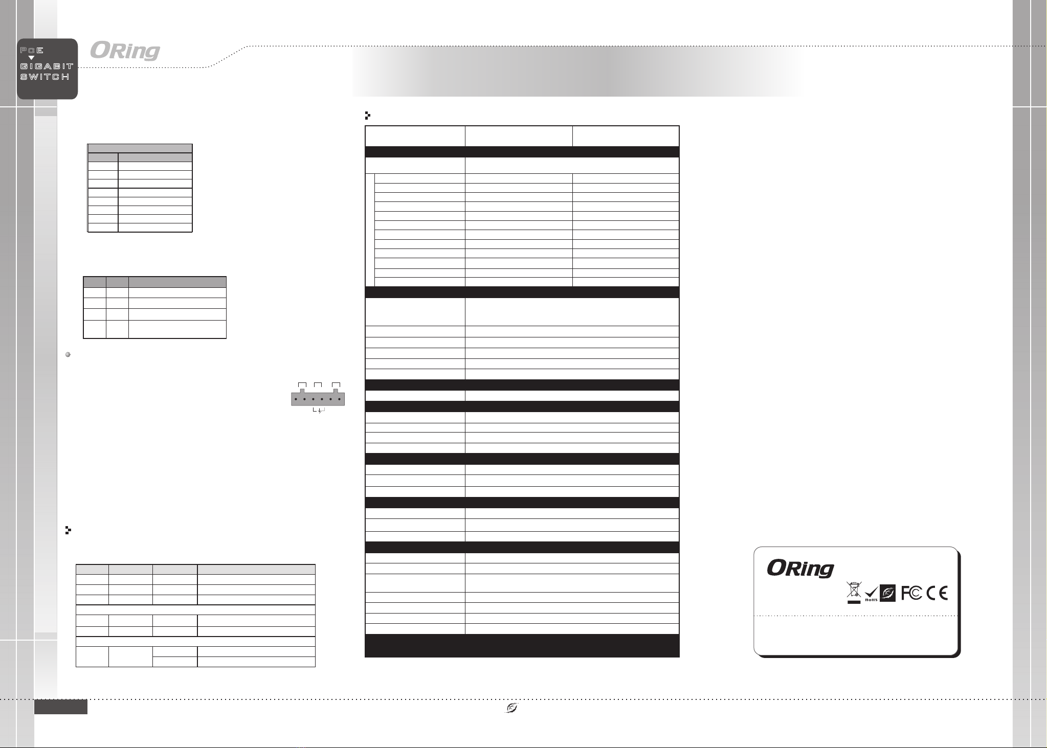
DIP Switch Setting
Wiring
The switch supports dual redundant power supplies, Power Supply1
(PWR1) and Power Supply 2 (PWR2). The connections for PWR1,
PWR2 and the RELAY are located on the terminal block.
STEP 1: Insert the negative/positive wires into the V-/V+ terminals,
respectively.
STEP 2: To keep the DC wires from pulling loose, use a small flat-
blade screwdriver to tighten the wire-clamp screws on the front of the
terminal block connector.
PWR-1PWR-2 1A@24V
V2- V2+ V1- V1+
Power inputs
The two sets of relay contacts of the 6-pin terminal block connector are used to detect user-
configured events. The two wires attached to the fault contacts form an close circuit when a
user-configured event is triggered. If a user-configured event does not occur, the fault
circuit remains opened.
Relay contact
Grounding and wire routing help limit the effects of noise due to electromagnetic
interference (EMI). Run the ground connection from the ground screws to the grounding
surface prior to connecting devices.
Grounding
Configurations
After installing the switch, the green power LED should turn on. Please refer
to the following tablet for LED indication.
Specifications
P1 Green On DC power 1 activated
P2 Green On DC power 2 activated
Fault Amber On Faulty relay (power failure or port disconnected)
10/100Base-T(X) PoE Ethernet ports
LNK/ACT Green On Port link at 10/100Mbps
PoE Green On Power supplied over Ethernet
100Base-FX fiber ports
LNK/ACT Green
On Port is connected
Blinking Transmitting data
10/100Base-T(X) P.S.E. RJ-45 port
TD+ with PoE Power Input +
TD- with PoE Power Input +
RD+ with PoE Power Input -
RD- with PoE Power Input -
For pin assignments for different types of cables, please refer to the following
tables.
Note: “+” and “-” signs represent the polarity of the wires that make up each
wire pair.
ORing Industrial Networking Corp.
Copyright© 2013 ORing
All rights reserved.
TEL: +886-2-2218-1066
FAX: +886-2-2218-1014
Website: www.oringnet.com
E-mail: support@oringnet.com
Version 1.3
DIP-2
OFF
OFF
ON
DIP-1
Power failure relay alarm disabled
PWR-1 failure, relay alarm enabled
PWR-2 failure, relay alarm enabled
OFF
ON
OFF
Description
ON PWR-1 or PWR-2 failure,
relay alarm enabled
ON
Industrial Unmanaged PoE Switch
ORing Switch Model
Physica l Ports
Technology
Eth ernet Sta ndards
<7u sSw itch Late ncy
10/1 00 Base-T(X) Ports in RJ45
Aut o MDI/MDIX with P.S.E.
IPS-10 42FA-MM-SC
4
IEEE 8 02.3 for 10Base -T
IEEE 8 02.3u for 100Ba se-TX and 100Bas e-FX
IEEE 8 02.3x for Flow co n trol
IEEE 8 02.3at PoE s pecificatio n (up to 30 Watts per port fo r P.S.E.)
MAC Table
1K MA C address es
Environmental
-40 t o 85 C (-40 t o 185 F)
o o
Sto rage Temperature
Ope rating Tempe rature
5% to 9 5% Non-co ndensin gOperat ing Humid ity
Regulatory Approvals
-40 t o 75 C (-40 t o 167 F)
o o
1.2 Gbps
Sw itch Band width
Fault Co ntact
Relay Relay outp ut to carry c apacity of 1A at 24 VDC
Power
Redundan t Input pow er
Power cons umption (Typ. ) 4 Watts (p ower cons umption o f P.S.E. is no t includ e d)
Overload cu rrent pro tection
Reverse p olarity p rotecti on
Pre sent
Pre sent
Physical Characteristic
Enc losure IP -30
Dim ension (W x D x H )
Weight ( g) 438 g
Dua l DC inputs 5 0-57VDC o n 6-pin ter minal blo ck
26. 1 (W) x 94.9 (D ) x 144.3 (H) m m (1.03 x 3.7 4 x 5.68 inc hes)
Pro cessing S tore-a nd-Fo rward
Fib er Port s Number 2
448 K bits
Packet bu ffer size
IPS-10 42FA-SS-SC
2
Fib er Port s standar d 100 Base-FX 100 Base-FX
Fib er Mode Mul ti-mode Sin gle-mod e
Fib er Diamet er (µm) 62. 5/125 µm & 50 /125 µm 9/1 25 µm
Fib er Optica l Connect or SC SC
Typical Dis tance (Km ) 2 Km 30 Km
Wave length (n m ) 131 0 nm 1310 nm
Max . Output Op tical Power (dbm ) -14 d bm -8 db m
Min . Output Op tical Power (dbm ) -23 .5 dbm -15 d bm
Max . Input Opt ical Po wer (Satu ration ) 0 dbm 0 dbm
Min . Input Opt ical Po wer (Sens itivity ) -31 d bm -34 d bm
Lin k Budget (d b) 7.5 d b 19 db
Fib er Port s Specifi cation
CE EM C (EN 55024 , EN 55032) , FCC Par t 15BEMC
EN 55 024 (IEC/ EN 61000- 4-2 (ESD) , IEC/EN 61 000-4-3 ( RS),IEC/ EN 61000- 4-4 (EFT),
IEC /EN 61000 -4-5 (Sur ge), IEC/ EN 61000- 4-6 (CS), I E C/EN 6100 0-4-8(P FMF),
IEC /EN 61000 -4-11 (DI P))
EMS
IEC 60068-2 -27Sho ck
IEC 60068-2 -31
IEC 60068-2 -6Vib ration
Fre e Fal l
MTBF
576 828 hrs
UL 60 950-1, CSA C22.2 No. 60950- 1-07, EN 60 950-1, IE C 60950-1Saf ety
EN 55 032, CISP R32, EN 610 00-3-2, E N 61000-3 -3, FCC Part 15B cla ss AEMI
Warran ty
5 ye ars
624 538 hrs
IGPS-1042GPA
IPS-1042FA Series
Note : HW version 5.0


