PKP PUM01 User manual

PKP Prozessmesstechnik GmbH
Borsigstrasse 24
D-65205 Wiesbaden-Nordenstadt
Tel: 06122 / 7055 - 0
Fax: 06122 / 7055 – 50
Operating Instructions
PUM01 / PUM02 / PUM03
Druckmessumformer

Contents
1 Introduction 2
2 Safety Information 2
3 Functional description 3
4 Installation instructions 3
5 Electrical connection 3
6 Care and Maintenance 3
7 Specifications See data sheet in the appendix
1 Introduction
Series PUM01-03 pressure transmitter are noted for their reliable function and easy operation. To obtain the
greatest benefit from this device, please observe the following cautionary statement:
Persons who are responsible for setting up or operating this device must be sure to read the and
understand the operating instructions and the safety information pertaining to it.
2 Safety Information
2.1 General Instructions
To ensure safe operation, the device must only be operated according to the information in the operating
instructions. When the device is in use, the regulations and safety standards applicable to the specific
application must also be observed. This statement also applies to the use of accessories.
2.2 Proper Usage
Series PUM01-03 pressure transmitters are designed to transform a pressure into an electrical output signal.
Any application extending beyond this specific intended use does not constitute proper usage.
Series PUM01-03 pressure transmitters must not be employed as the sole means of avoiding hazardous
conditions in machinery and installations.
The machinery and installations must be designed in such a manner that faulty conditions and malfunctions
will not present hazardous situations for operating personnel.
2.3 Qualified Personnel
Series PUM01-03 must only be used by qualified, knowledgeable personnel trained in correct use of these
devices. Qualified personnel are those persons familiar with setting up and assembling these devices, placing
them in service and operating them. In addition, such personnel must also be qualified to perform the work
associated with the application for which the device is being used.
PUM01-~1.SAM 12.07.05 Page 2

3 Functional Description
The pressure is sensed in the transmitter by means of a piezo-resistive cell or a thin-film cell. The resulting
resistance signal, varying with the pressure, is converted by an amplifier to a current or voltage signal.
4 Installation Instructions
4.1 General Information
The actual operating pressure and temperature of the installation must not exceed the maximum values
specified. The pressure ports must only be opened with the system depressurized. Please note that in a given
system, the component with the lowest maximum pressure rating will determine the maximum permissible
operating pressure for the entire system.
4.2 Pressure Transmitter (high-pressure version)
For the proper tightening torques, please refer to the documentation from the supplier of your high-pressure
piping.
5 Electrical Connection
For the pin assignment, please refer to the label on the transmitter.
6 Care and Maintenance
PKP pressure transmitters are maintenance-free.
Recommended recalibration interval: 1 year
PUM01-~1.SAM 12.07.05 Page 3

1/08
Pressure Measurement and Monitoring Systems
252
PUM03
High-Precision
Pressure Transmitter
in Stainless Steel
• Accuracy class 0.25
• Measures relative or absolute pressure
• Optional flush-mounted
stainless steel diaphragm
• Sturdy, heavy-duty design
• Current or voltage output
Description:
Model series PUM03 pressure sensors have a piezo-resistive
sensor element for pressure ranges up to 16 bar. This ele-
ment very accurately registers changes in pressure through
the change in the electrical resistance of the piezo crystal
caused by variation in the mechanical force exerted upon it.
For higher measuring ranges, thin-film technology
is used due to its fast reaction times. This method translates
the changes in resistance in an extremely thin strip of ex-
panding film into an output signal that is proportional to the
mechanical force exerted upon the film. The combination of
these two technologies allows this device to meet all DIN
measuring ranges from -1/0 bar to 0/2500 bar with consistent
accuracy.
Fields of Application:
The sturdy design of PUM03 pressure transmitters allows
accurate measurement of gases and liquids in a process,
even under rough service conditions. A stainless-steel dia-
phragm protects the transmitter measuring system from
damage, allowing a great variety of media to be measured
as long as they are not highly viscous or crystallizing. If
necessary, the pressure transmitter can be fitted with a flush-
mounted diaphragm which prevents these kinds of materials
from entering the housing and hardening there. The electri-
cal signal at the output can be remotely transmitted or used
for direct display. For direct display of readings, we recom-
mend the PKP AZ01 digital display, which can be easily
installed between the transmitter and the plug connector.
This display does not require a separate power supply.
PKP Process Instruments Inc.
10 Brent Drive · Hudson, MA 01749
SS+1-978-212-0006 · TT+1-978-568-0060
PKP Prozessmesstechnik GmbH
Borsigstraße 24 · D-65205 Wiesbaden
SS+49 (0) 6122-7055-0 · TT+49 (0) 6122-7055-50

253
Ordering Code:
order number: PUM03.
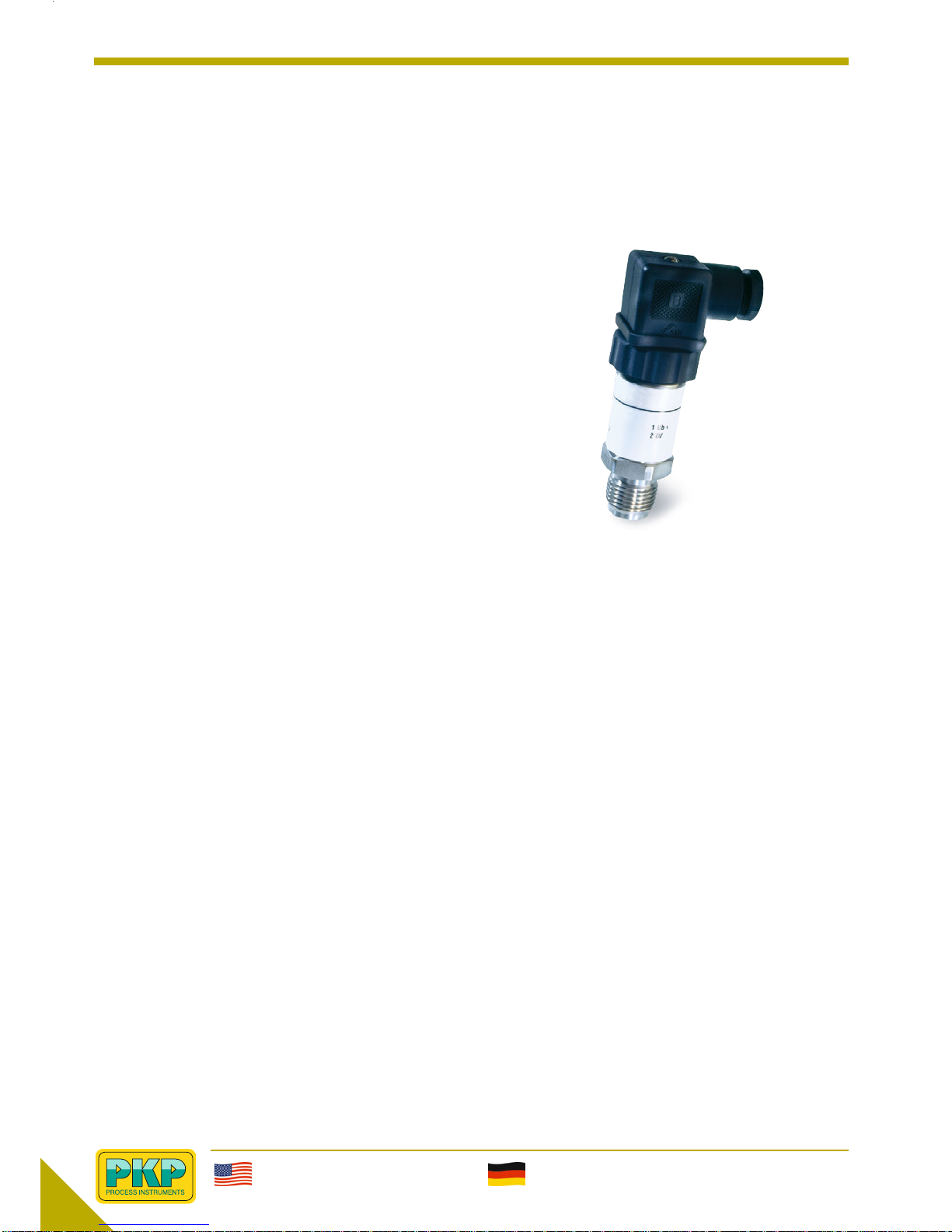
Pressure transmitter, class 0.25
Output signal:
1 = 4 to 20 mA, 2-wire
2 = 0 to 10 V, 3-wire
Calibration:
1 = Relative pressure
2 = Absolute pressure
Electrical connection:
1 = Plug connector
2 = Permanently attached connection cable
Process connection:
1 = G1/2 B
2 = G 1 B (with flush-mounted diaphragm
for measuring range of 0 to 1.6 bar)
3 = M16 X 1.5 female thread (for measuring range > 1600 bar)
4 = Special thread (G1/4, 1/4“ NPT, 1/2“ NPT)
Design:
1 = Internal diaphragm
2 = Flush-mounted diaphragm
Measuring range:
R = relative A = absolute
R13 = -0.25 - 0 bar
R14 = -0.4 - 0 bar
R15 = -0.6 - 0 bar
R16 = -1 - 0 bar
R43 = -1 - 1.5 bar
R45 = -1 - 5 bar
R65 = 0 - 0.25 bar A65 = 0 - 0.25 bar
R66 = 0 - 0.4 bar A66 = 0 - 0.4 bar
R67 = 0 - 0.6 bar A67 = 0 - 0.6 bar
R69 = 0 - 1 bar A69 = 0 - 1 bar
R70 = 0 - 1.6 bar A70 = 0 - 1.6 bar
R72 = 0 - 2.5 bar A72 = 0 - 2.5 bar
R73 = 0 - 4 bar A73 = 0 - 4 bar
R74 = 0 - 6 bar A74 = 0 - 6 bar
R75 = 0 - 10 bar A75 = 0 - 10 bar
R76 = 0 - 16 bar A76 = 0 - 16 bar
R78 = 0 - 25 bar
R79 = 0 - 40 bar
R80 = 0 - 60 bar
R81 = 0 - 100 bar
R82 = 0 - 160 bar
R84 = 0 - 250 bar
R85 = 0 - 315 bar
R86 = 0 - 400 bar
R87 = 0 - 600 bar
R88 = 0 - 1000 bar (without flush-mounted diaphragm)
R89 = 0 - 1600 bar (without flush-mounted diaphragm)
R90 = 0 - 2500 bar (without flush-mounted diaphragm)
2.1.2. 1. 1. R76
Designs:
PUM02 Pressure Transmitters, Class 0.25
Output signal: possible output signals are: Current signal
4 to 20 mA in two-wire circuitry or voltage signal 0 to 10 V
in three-wire circuitry (other outputs available upon request)
Calibration: If desired, these devices can be calibrated up
to a measuring range of 0 to 16 bar at absolute pressure.
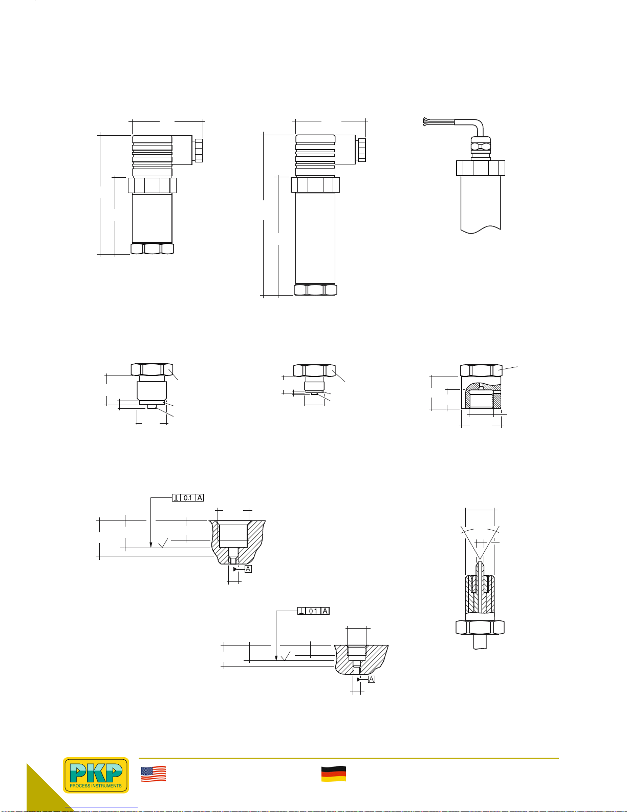
Electrical connection: standard DIN EN 175301-803 plug
connector, model A with cable box. Permanently attached
connection cable optional, standard length of 1m
Process connection: If desired, these devices can be
supplied with a flush-mounted stainless-steel diaphragm for
a measuring range up to 0 to 600 bar. This will be neces-
sary for use with viscous or sticky fluids.
Electrical specifications:
Supply voltage: 10 to 30 VDC with current output
14 to 30 VDC with voltage output
Power consump-
tion Max.: 20 mA
Output: voltage output load ≥5 kOhm
current output load ≤(U-10V) / 0.02 A
Interference
emission: as per EN 61326
Noise immunity: as per EN 61326
Protection type: IP65 EN 60 529 / IEC 529
Electrical
protection types: incorrect polarity, overvoltage,
and short-circuit protection
Technical details:
Process G1/2 B male thread, with flush-
connection: mounted G1 B diaphragm for
measuring range of 0 to 1.6 bar
M16x1.5 female thread for mea-
suring range > 1600 bar
Optional
connections: G1/4,1/4” NPT and 1/2” NPT
Parts in contact
with media: stainless steel 1.4571 and 1.4542
(with flush-mounted diaphragm,
1.4571 only)
Max. pressure: 3.5 times the upper range value
for measuring range up to 16 bar
2 times the upper range value
for measuring range to 600 bar
1.5 times the upper range value
for measuring range > 600 bar
1.2 times the upper range value
for measuring range = 1600 bar
1.2 times the upper range value
for measuring range = 2500 bar
Max. media temp.: -30…+100°C
Max. ambient temp.: -20…+80°C
Max. storage temp.: -40…+100°C
Compensated range: 0 to 80°C
Housing: stainless steel,
European standard no. 1.4301
Weight: approx. 0.2 kg
Accuracy: class 0.25
Reproducibility: < +/- 0.05% f. s.
Response time: 1 ms (between 10%…90% f. s.)
Adjustability: zero-point and measuring range
up to 10%
PKP Process Instruments Inc.
10 Brent Drive · Hudson, MA 01749
SS+1-978-212-0006 · TT+1-978-568-0060
PKP Prozessmesstechnik GmbH
Borsigstraße 24 · D-65205 Wiesbaden
SS+49 (0) 6122-7055-0 · TT+49 (0) 6122-7055-50

1/08
254
PUM02/PUM03 – Pressure Transmitters
Dimensions
Housing – design with plug connector as per DIN43650
Short design Long design cable outlet
48 48
82
20
G1/2
SW27
ø6
ø17.5
3
3
24.5 +1 19 -0.5 min.14.5
G1/2
ø7
DIN16288
x
16.5 +1
13 -0.5 min.9.5
G1/4 DIN16288
ø5,5
x
13
G1/4
SW27
ø9.5 19.5
60°
12
SW27
ø26.5
M16x1.5
M16x1,5
2
2
max.
105
75
54 ø27
ø27
ø27
Pressure ports
G1/2B G1/4B high-pressure threaded connection
M16x1.5 female
Tapped hole and/or thread adapter as per DIN16288
G1/2 high-pressure threaded connection
M16x1.5 female
G1/4
ø5
ø4,8
PKP Process Instruments Inc.
10 Brent Drive · Hudson, MA 01749
SS+1-978-212-0006 · TT+1-978-568-0060
PKP Prozessmesstechnik GmbH
Borsigstraße 24 · D-65205 Wiesbaden
SS+49 (0) 6122-7055-0 · TT+49 (0) 6122-7055-50
This manual suits for next models
2
Table of contents
Other PKP Transmitter manuals