Meas. system piezoresistive: MR: 0,1...0 to 0...25 bar
Meas. system thin film: MR: 0...40 to 0...2500 bar
Technical Data:
Process connection: G ½ B male thread
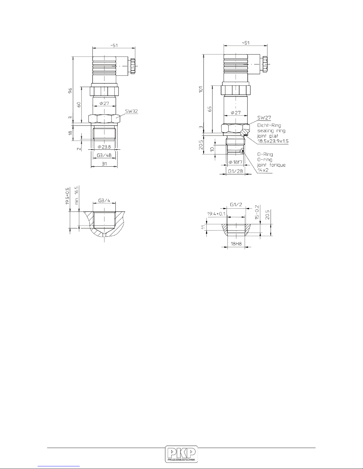
G ¾ B with front flush membrane
(to MR R78 0...25 bar)
G ½ B with front flush membrane
(at MR R79 0...40 bar)
G ¼ female
other designs on request
Material:
Housing: stainless steel 1.4301
Pressure port: stainless steel 1.4571
Pressure sensor: 1.4435 (piezoresistive)
1.4545 (thin-film)
Media temperature: −25 ... +80 °C
Ambient temperature: −20 ... +70 °C
Storage temperature: −40 ... +100 °C
Accuracy: according to EC 61298-2
linearity+hysteresis+repeatability:
<0,3 % FS, <0,2 % BFSL
Temperature error: average TK zero point:
<0,2 % FS / 10 K
average TK range:
<0,2 % FS / 10 K
Reaction time: < 10 ms
Weight: ca. 0,24 kg
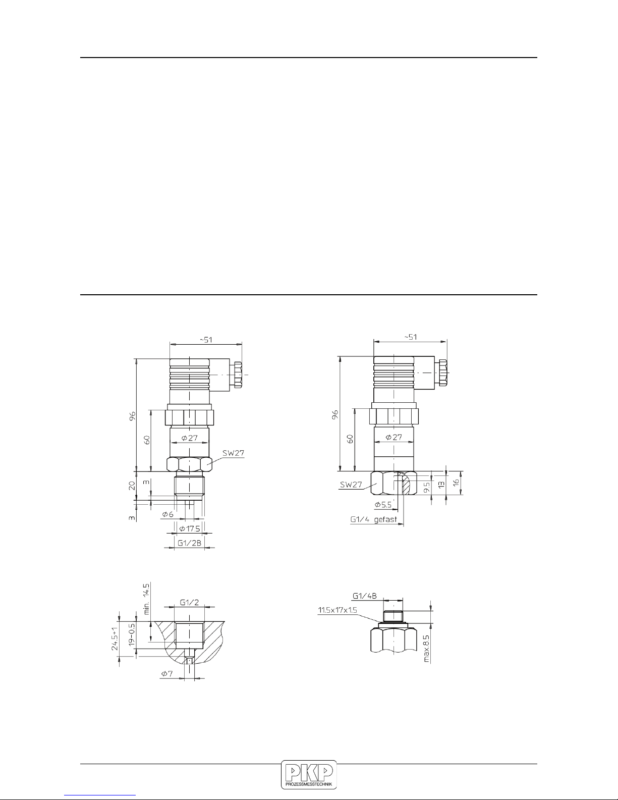
Dimensions:
G ½ B, inside
membrane
* 101 mm at thin-film technology
(from MR R79: 0...40 bar)
** 65 mm at thin-film technology
(from MR R79: 0...40 bar)
Order Code:
Order number: PUM06.
Universal pressure transmitter
2. 1. 2. 1. R76. 0
Output signal:
1 = 4 bis 20 mA, 2-wire
2 = 0 bis 10 V, 3-wire
Calibration:
1 = relative pressure
2 = absolute pressure
Electrical connection:
1 = angle plug, P65, EN 175301-803 form A
2 = fixed connection cable P68 (1 m standard length)
Process connection:
1 = G ½ B male, acc. to EN 837-1, inside membrane
2 = G ¾ B male front flush membrane (up to MR R78)
3 = G ½ B male front flush membrane (from MR R79)
4 = G 1 B male front flush membrane
5 = G ¼ female, inside membrane
9 = special connection (please specify in plain text)
Measuring range / Overrange limit:
R = relative A = absolute
R11 = -0,10...0 bar / 0,6 bar
R12 = -0,16...0 bar / 0,6 bar
R13 = −0,25...0 bar / 0,6 bar
R14 = −0,4...0 bar / 2,0 bar
R15 = −0,6...0 bar / 2,0 bar
R16 = −1...0 bar / 2,0 bar
R43 = −1...1,5 bar / 4 bar
R45 = −1...5 bar / 13 bar
R63 = 0...0,1 bar / 0,6 bar
R64 = 0...0,16 bar / 0,6 bar
R65 = 0...0,25 bar / 0,6 bar A65 = 0...0,25 bar / 0,6 bar
R66 = 0...0,4 bar / 2,0 bar A66 = 0...0,4 bar / 2,0 bar
R67 = 0...0,6 bar / 2,0 bar A67 = 0...0,6 bar / 2,0 bar
R69 = 0...1 bar / 2,0 bar A69 = 0...1 bar / 2,0 bar
R70 = 0...1,6 bar / 4 bar A70 = 0...1,6 bar / 4 bar
R72 = 0...2,5 bar / 6 bar A72 = 0...2,5 bar / 6 bar
R73 = 0...4 bar / 13 bar A73 = 0...4 bar / 13 bar
R74 = 0...6 bar / 13 bar A74 = 0...6 bar / 13 bar
R75 = 0...10 bar / 32 bar A75 = 0...10 bar / 32 bar
R76 = 0...16 bar / 32 bar A76 = 0...16 bar / 32 bar
R78 = 0...25 bar / 32 bar
R79 = 0...40 bar / 80 bar
R80 = 0...60 bar / 108 bar
R81 = 0...100 bar / 170 bar
R82 = 0...160 bar / 256 bar
R84 = 0...250 bar / 400 bar
R86 = 0...400 bar / 600 bar
R87 = 0...600 bar / 840 bar
R88 = 0...1000 bar / 1400 bar
R89 = 0...1600 bar / 2080 bar further measuring ranges
R90 = 0...2500 bar / 3000 bar on request
Options:
0 = without
9 = please specify in plain text
Accessory: Self powered plug-in display AZ01
Electrical Data:
Power supply: 7,5...30 VDC at current output
12...30 VDC at voltage output
Power consumption: max. 0,75 W
Output: current output 4...20 mA, 2-wire.
load = (U-7,5 V) / 0,025 A
voltage output 0...10 V, 3-wire.
load > 10 kOhm
special range factory adjustable
Transient emissions: according to EN 61326
Immunity: according to EN 61326
Protection class: P65 EN 60 529 / EC 529
P68 with cable connection
PKP Prozessmesstechnik GmbH
Borsigstr. 24 • D-65205 Wiesbaden
S +49 (0) 6122-7055-0 • +49 (0) 6122 7055-50
PKP Process Instruments Inc.
10 Brent Drive • Hudson, MA 01749
S +1-978-212-0006 • +1-978-568-0060
Druck
G ¾ B AG,
front flush
G ½ B
male
thread,
front
flush
G 1 B male
thread,
front flush
G ¼
female
thread