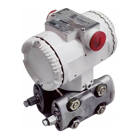
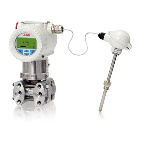
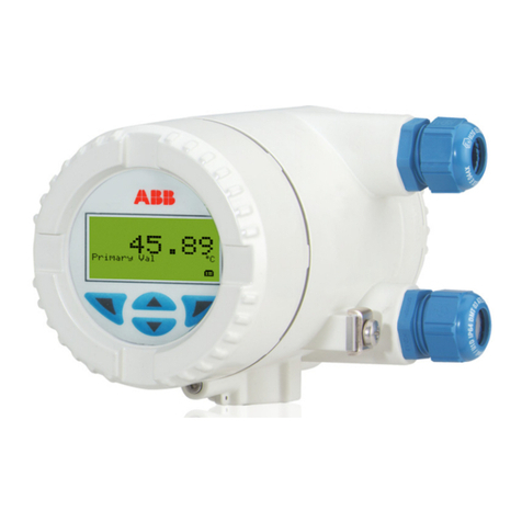
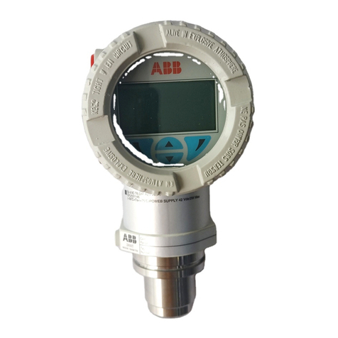
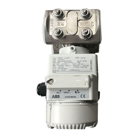
ABB 266 DDS User manual

—
ABB MEASUREMENT & ANALYTICS | OPERATING INSTRUCTION
266 DDS Digital Diaphragm Seal - HART Version
Pressure transmitters
Engineered solutions for all
applications
Measurement made easy
Introduction
The present manual provides information on
installing, operating, troubleshooting the 266 digital
diaphragm seal (DDS) configuration, a solution
based on the existing 266 gauge and absolute
pressure transmitter models. Every section of the
present manual is specifically dedicated to the
specific phase of the transmitter lifecycle starting
from the receipt of the transmitter and its
identification, passing to the installation, to the
electrical connections, to the configuration and to
the troubleshooting and maintenance operations.
The pressure transmitters model 266DDS is a
modular range of field mounted, microprocessor
based electronic transmitters, using multiple sensor
technologies. Accurate and reliable measurement of
gauge for gas ad liquid level is provided, in the even
most difficult and hazardous industrial
environments.
Model 266 can be configured to provide specific
industrial output signals according to 4 to 20mA
with HART digital communication.
For more information
Further publications for 2600T series pressure
products are available for free download from:
www.abb.com/measurement
or by scanning this code:
Download the Brochure or search for
RB/2600T-EN on https://library.abb.com/en.
—
266 DDS models

2266 DDS HART | PRESSURE TRANSMITTERS | OI/266DDS-EN REV. A
Contents
1 Safety ..................................... 4
General safety information. . . . . . . . . . . . . . . . . . . . . . . . . 4
Improper use...................................... 4
Technical limit values .............................. 4
Warranty provision ................................ 4
Use of instruction ................................. 4
Operator liability ...................................5
Qualified personnel ................................5
Returning devices ..................................5
Disposal ...........................................5
Information on WEEE Directive 2012/19/EU
(Waste Electrical and Electronic Equipment) .........5
Transport and storage ..............................5
Safety information for electrical installation .........5
Safety information for inspection and maintenance . 6
Cyber security .................................... 6
Disclaimer....................................6
Communication protocol specific..............6
2 Transmitter overview ........................7
Transmitter components overview ..................7
Range and span consideration ......................7
3 Opening the box .............................8
Identification plates ............................... 8
Optional wired-on plate ........................... 8
Handling and storage.............................. 9
4 Mounting ...................................9
General ........................................... 9
IP protection and designation......................10
Mounting the transmitter..........................10
Transmitter factory configuration
consideration ...............................10
Hazardous area considerations...............10
Pressure Equipment Directive (PED)
(2014/68/EU) .....................................10
Devices with PS >200 ........................10
Devices with PS ≤200 ........................10
Mounting a P style pressure transmitter ............11
Sealing and screw connections.....................11
Moisture ..........................................11
Measuring pipe ...................................12
5 Transmitter wiring..........................13
Supply requirement ...............................13
Cable connection..................................13
Wiring procedure..................................14
Grounding ........................................14
Output (HART) transmitter wiring..................15
Communication setup .............................15
6 Commissioning .............................16
General remarks...................................16
Output signal .....................................16
Output current limits for analog only version ..16
Output current limits for HART and analog
version (according to NAMUR NE 43 standard). 16
Zero/Span and write protection....................16
Local display ......................................17
Adjusting lower range value / oblique sensors ......18
Installing/Removing the LCD display ...............19

266 DDS HART | PRESSURE TRANSMITTERS | OI/266DDS-EN REV. A 3
7 Operation (only HART version) ..............21
LCD display. .......................................21
Local diagnostic menu. ............................21
LCD menu structure. ..............................21
Easy setup menu ................................. 22
8 Error messages .............................23
LCD display messages ............................ 23
Error states and alarms ........................... 23
QR code Digital Advanced Diagnostic (DAD) ....... 26
QR code Channel Partner Support ................. 26
9 Maintenance / Repair .......................27
Returns and removal...............................27
10 Hazardous Area considerations............. 28
Special condition for safe use (X).................. 28
Explosion protection ............................. 28
Type-examination certificate/Declaration of
conformity....................................... 28
Type of protection................................ 28
Use in areas with combustible dust................ 28
Use of handheld terminal / PC..................... 28
Hazardous atmospheres.......................... 29
ATEX ........................................29
IECEx .......................................29
Canadian Standards Association (US) .........30
Canadian Standards Association (Canada) ....30

4266 DDS HART | PRESSURE TRANSMITTERS | OI/266DDS-EN REV. A
1 Safety
General safety information
The “Safety” section provides an overview of the safety aspects
to be observed for operation of the device.
The device has been constructed in accordance with the state
of the art and is operationally safe. It has been tested and left
the factory in perfect working conditions. The information in
the manual, as well as the applicable documentation and
certificates, must be observed and followed in order to
maintain this condition throughout the period of operation.
Full compliance with the general safety requirements must be
observed during operation of the device. In addition to the
general information, the individual sections in the manual
contain descriptions of processes or procedural instructions
with specific safety information.
Only by observing all of the safety information can you reduce
to the minimum the risk of hazards for personnel and/or
environment. These instructions are intended as an overview
and do not contain detailed information on all available models
or every conceivable event that may occur during setup,
operation, and maintenance work.
For additional information, or in the event of specific problems
not covered in detail by these operating instructions, please
contact the manufacturer. In addition, ABB declares that the
contents of this manual are not part of any prior or existing
agreements, commitments, or legal relationships; nor are they
intended to amend these.
All obligations of ABB arise from the conditions of the relevant
sales agreement, which also contains the solely binding
warranty regulations in full. These contractual warranty
provisions are neither extended nor limited by the information
provided in this manual.
Only qualified and authorized specialist personnel should
be charged with installation, electrical connection,
commissioning, and maintenance of the transmitter.
Qualified personnel are persons who have experience in
installation, electrical wiring connection, commissioning, and
operation of the transmitter or similar devices, and hold the
necessary qualifications such as:
• Training or instruction, i.e., authorization to operate and
maintain devices or systems according to safety
engineering standards for electrical circuits, high
pressures, and aggressive media
• Training or instruction in accordance with safety
engineering standards regarding maintenance and use of
adequate safety systems.
For safety reasons, ABB draws your attention to the fact that
only sufficiently insulated tools conforming to EN 60900 may
be used.
Since the transmitter may form part of a safety chain, we
recommend replacing the device immediately if any defects
are detected. In case of use in Hazardous Area non sparking
tools only must be employed.
In addition, you must observe the relevant safety regulations
regarding the installation and operation of electrical systems,
and the relevant standards, regulations and guidelines about
explosion protection.
The device can be operated at high levels of pressure and
with aggressive process media. As a result, serious injury or
significant property damage may occur if this device is
operated incorrectly.
Improper use
It is prohibited to use the device for the following purposes:
• As a climbing aid, e.g., for mounting purposes.
• As a support for external loads, e.g., as a support for pipes.
• Adding material, e.g., by painting over the name plate or
welding/soldering on parts.
• Removing material, e.g., by drilling the housing.
Repairs, alterations and enhancements, or the installation of
replacement parts are only permissible as far as these are
described in the manual. Approval by ABB must be requested
for any activities beyond this scope. Repairs performed by
ABB-authorized centers are excluded from this.
Technical limit values
The device is designed for use exclusively within the values
stated on the name plates and within the technical limit values
specified on the data sheets.
The following technical limit values must be observed:
• The Maximum Working Pressure may not be exceeded.
• The Maximum ambient operating temperature may not be
exceeded.
• The Maximum process temperature may not be exceeded.
• The enclosure method of protection type must be
observed.
Warranty provision
Using the device in a manner that does not fall within the scope
of its intended use, disregarding this manual, using
underqualified personnel, or making unauthorized alterations,
releases the manufacturer from any liability for any resulting
damage. This makes the manufacturer’s warranty null and void.
Use of instruction
Serious damage to health/risk to life.
This message indicates that an imminent risk is present.
Failure to avoid this will result in death or serious injury.
CAUTION
WARNING
DANGER
266 DDS HART | PRESSURE TRANSMITTERS | OI/266DDS-EN REV. A 5
Bodily injury.
This message indicates a potentially dangerous situation.
Failure to avoid this could result in death or serious injury.
Minor injuries.
This message indicates a potentially dangerous situation.
Failure to avoid this could result in minor injuries. This may
also be used for property damage warnings.
This message indicates indicates operator tips or particularly
useful information. It does not indicate a dangerous or
damaging situation.
Property damage.
This message indicates a potentially damaging situation.
Failure to avoid this could result in damage to the product or
its surrounding area.
Operator liability
Prior to using corrosive and abrasive materials for
measurement purposes, the operator must check the level of
resistance of all parts coming into contact with the materials to
be measured.
ABB will gladly support you in selecting the materials, but
cannot accept any liability in doing so.
The operators must strictly observe the applicable national
regulations with regard to installation, function tests, repairs,
and maintenance of electrical devices.
Qualified personnel
Installation, commissioning, and maintenance of the device
may only be performed by trained specialist personnel who
have been authorized by the plant operator. The specialist
personnel must have read and understood the manual and
comply with its instructions.
Returning devices
Use the original packaging or suitably secure shipping package
if you need to return the device for repair or recalibration
purposes.
According to EU guidelines and other local laws for hazardous
materials, the owner of hazardous waste is responsible for its
disposal. The owner must observe the proper regulations for
shipping purposes.
All devices sent back to ABB must be free from any hazardous
materials (acids, alkalis, solvents, etc.).
Disposal
ABB actively promotes environmental awareness and has an
operational management system that meets the requirements
of ISO 9001:2015, ISO 14001:2015, and OHSAS 18001:2007.
Our products and solutions are intended to have minimum
impact on the environment and persons during manufacturing,
storage, transport, use and disposal.
This includes the environmentally friendly use of natural
resources. ABB conducts an open dialog with the public
through its publications.
This product/solution is manufactured from materials that can
be reused by specialist recycling companies.
Information on WEEE Directive 2012/19/EU
(Waste Electrical and Electronic Equipment)
This product or solution is subject to the WEEE Directive
2012/19/EU or corresponding national laws. Starting from
August 15th 2018, electrical and electronic equipment marked
with the crossed-out wheeled bin symbol may not be disposed
as unsorted municipal waste. Waste of electrical and electronic
equipment (WEEE) shall be treated separately using the
national collection framework available to customers for the
return, recycling and treatment of WEEE.
Proper disposal prevents negative effects on people and the
environment, and supports the reuse of valuable raw materials.
ABB can accept and dispose of returns for a fee.
Transport and storage
• After unpacking the pressure transmitter, check the device
for transport damage.
• Check the packaging material for accessories.
• During intermediate storage or transport, store the
pressure transmitter in the original packaging only.
For information on permissible ambient conditions for storage
and transport, see chapter “4 Handling and storage” and
product datasheet. Although there is no limit on the duration of
storage, the warranty conditions stipulated on the order
acknowledgment from the supplier still apply.
Safety information for electrical installation
Electrical connections may only be established by authorized
specialist personnel in accordance with the electrical circuit
diagrams. The electrical connection information in the manual
must be observed; otherwise, the applicable protection type
may be affected. Ground the measurement system according
to requirements.
WARNING
CAUTION
NOTICE
IMPO RTANT

6266 DDS HART | PRESSURE TRANSMITTERS | OI/266DDS-EN REV. A
...1 Safety
Safety information for inspection and
maintenance
There is no EMC protection or protection against accidental
contact when the housing cover is open. There are electric
circuits within the housing which are dangerous if touched.
Therefore, the auxiliary power must be switched off before
opening the housing cover.
The device can be operated at high pressure and with
aggressive media. Any process media released may cause
severe injuries. Depressurize the pipeline/tank before
opening the transmitter connection.
Corrective maintenance work may only be performed by trained
personnel.
– Before removing the device, depressurize it and any
adjacent lines or containers.
– Check whether hazardous materials have been used as
materials to be measured before opening the device.
– Residual amounts of hazardous substances may still be
present in the device and could escape when the device is
opened.
Within the scope of operator responsibility, check the
following as part of a regular inspection:
• Pressure-bearing walls/lining of the pressure device
• Measurement-related function
• Leak-tightness
• Wear (corrosion)
Cyber security
Disclaimer
This product is designed to be connected to and to
communicate information and data via a network interface. It is
operator’s sole responsibility to provide and continuously
ensure a secure connection between the product and your
network or any other network (as the case may be). Operator
shall establish and maintain any appropriate measures (such as
but not limited to the installation of firewalls, application of
authentication measures, encryption of data, installation of
anti-virus programs, etc) to protect the product, the network,
its system and the interface against any kind of security
breaches, unauthorized access, interference, intrusion, leakage
and/or theft of data or information.
ABB and its affiliates are not liable for damages and/or losses
related to such security breaches, any unauthorized access,
interference, intrusion, leakage and/or theft of data or
information.
Communication protocol specific
The HART protocol is an unsecured protocol, such as the
intended application should be assessed to ensure that these
protocols are suitable before implementation.
WARNING - RISK TO PERSONS

266 DDS HART | PRESSURE TRANSMITTERS | OI/266DDS-EN REV. A 7
2 Transmitter overview
Transmitter components overview

8266 DDS HART | PRESSURE TRANSMITTERS | OI/266DDS-EN REV. A
...2 Transmitter overview
Range and span consideration
The 2600T Transmitter data sheets provide all information concerning the Range and Span limits in relation to the model and the
sensor code.
The terminology currently used to define the various parameters is as follows:
• URL: Upper Range Limit of a specific sensor. The highest value of the measured value that the transmitter can be adjusted to
measure.
• LRL: Lower Range Limit of a specific sensor. The lowest value of the measured value that the transmitter can be adjusted to
measure.
• URV: Upper Range Value. The highest value of the measured value to which the transmitter is calibrated.
• LRV: Lower Range Value. The lowest value of the measured value to which the transmitter is calibrated.
• SPAN: The algebraic difference between the Upper and Lower Range Values. The minimum span (MIN SPAN) is the minimum
value that can be used without degradation of the specified performance. The calibration span (CAL SPAN) is the difference
between Upper Range Value (URV) and Lower Range Value (LRV).
• TD: (or Turn Down Ratio) is the ratio between the maximum span and the calibrated span.
The transmitter can be calibrated with any range between the LRL and the URL with the following limitations:
– LRL ≤LRV ≤(URL - CAL SPAN)
– CAL SPAN ≥MIN SPAN
– URV ≤URL

FM16CA0036X - FM16US0066X
A
B
C
2600T
Tag
Number
Calib.
Range
PRESSURE TRANSMITTER
jl ABB S.p.A. SERIAL 0
Q
mm
0
DD
266 DDS HART | PRESSURE TRANSMITTERS | OI/266DDS-EN REV. A 9
3 Opening the box
Identification plates
The instrument is identified by the data plates shown in Figure 3. The certification plate (ref. A): contains the certification related
parameters for use in Hazardous area.
The Nameplate (ref. B), always made of AISI 316 ss, provides information concerning the model code, maximum working pressure,
range and span limits, power supply, output signal, diaphragms material, fill fluid, range limit, serial number, maximum process
working pressure (PS) and temperature (TS).
The Tag plate, instead, provides customer tag number and calibrated range.
Both certification and tag plates are supplied self-adhesive attached to the electronics housing, as standard. Option I2 allows
to select these plates as metal AISI 316 ss fastened to the electronics housing with rivets.
The instrument may be used as a pressure accessory as defined by the Pressure Equipment Directive 2014/68/EU:
• category III module H for PS > 20 MPa, 200 bar
• art. 4, par. 3 Sound Engineering Practice (SEP) for PS < 20 MPa, 200 bar and for all PS values of 266DDS with remote seals.
In this case, near the CE mark, you will find the number of the notified body (0474) that has verified the compliance according to
module H.
266DDS pressure transmitters comply with directive EMC 2014/30/EU.
The certification plate is issued by ABB S.p.A, 22016 Tremezzina, Italy, with the numbers:
• FM20ATEX00XXX or IECEx FME 20.000XX (Ex d, Ex tb)
CE-Identification number of the notified bodies to Pressure Equipment Directive: 0474, to ATEX certification: 0722, to IECEx
certification: IT/CES/QAR07.0001.
PRIMARY UNIT SECONDARY UNIT

10 266 DDS HART | PRESSURE TRANSMITTERS | OI/266DDS-EN REV. A
Optional wired-on plate
The 266 DDS transmitter can be supplied with the optional
“Wired On Stainless Steel plate” (figure 4) which is permanently
laser printed with a custom text specified in phase of order.
The available space consists in 4 lines with 32 characters per
line.
The plate will be connected to the transmitter with a Stainless
Steel wire.
Handling and storage
The instrument does not require any special precautions during
handling although normal good practice should be observed.
The instrument does not require any special treatment if stored
as dispatched and within the specified ambient conditions.
There is no limit to the storage period, although the terms of
guarantee remain as agreed with the Company and as given in
the order acknowledgement.
Standard delivery items
Primary and secondary devices are supplied loose, the
connection is provided by the customer according to this
operating instruction.
Please check the right combination by looking on the name
plate.
4 Mounting
General
Study these installation instructions carefully before
proceeding.
Failure to observe the warnings and instructions may cause a
malfunction or personal hazard. Before installing the
transmitter, check whether the device design meets the
requirements of the measuring point from a measurement
technology and safety point of view.
This applies in respect of the:
• Explosion protection certification
• Measuring range
• Gauge pressure stability
• Temperature (Ambient and Process)
• Operating voltage and current
The suitability of the materials must be checked as regards
their resistance to the media. This applies in respect of the:
• Process connection, isolating diaphragm, etc.
In addition, the relevant directives, regulations, standards, and
accident prevention regulations must be observed.
Measurement accuracy is largely dependent on correct
installation of the pressure transmitter and, if applicable, the
associated measuring pipe(s). As far as possible, the measuring
setup should be free from critical ambient conditions such as
large variations in temperature, vibrations, or shocks.
If unfavorable ambient conditions cannot be avoided for
reasons relating to building structure, measurement
technology, or other issues, the measurement quality may be
affected. If a remote seal with capillary tube is installed on
the transmitter, the additional operating instructions for
remote seals and the related data sheets must be observed.
IMPO RTANT

266 DDS HART | PRESSURE TRANSMITTERS | OI/266DDS-EN REV. A 11
...4 Mounting
IP protection and designation
The housings for 266DDS transmitters are certified as
conforming to protection type IP66 / IP67 (according to
IEC 60529) or NEMA 4X (according to NEMA 250).
The first number indicates the type of protection the
integrated electronics have against the entry of foreign bodies,
including dust.
“6” means that the housing is dust-proof (i.e., no ingress of
dust).
The second number indicates the type of protection the
housing has against the entry of water.
“6” means that housing is protected against water; specifically,
powerful jets of water under standardized conditions.
“7” means that the housing is protected against the effects of
temporary immersion in water under standardized water
pressure and temporal conditions.
The device and its accessories (i.e. cable glands and other
electrical connections) must be carefully and duly tightened to
meet expected IP protection type.
When using/mounting cable glands, they have to meet
expected IP rating.
Mounting the transmitter
Transmitter factory configuration consideration
The 266DDS pressure transmitter in your hands has been
factory calibrated to reflect the published declared
performance specification; no further calibration is required in
normal condition. ABB typically configures 266DDS pressure
transmitters according to the user requirements. A typical
configuration includes:
• TAG number
• Calibrated span
• Output linearization
• LCD display configuration
Hazardous area considerations
The transmitter must be installed in hazardous area only if it is
properly certified. The certification plate is permanently fixed
on the housing of the transmitter. Transmitter can have the
following certifications:
• ATEX Europe (code E2) approval
• IECEx (code E9) approval
• Combined FM (code EB) approvals (US and Canada)
Type 4X, IP66, IP67 for all above markings.
Technical Regulations Customs Union EAC (Russia,
Kazakhstan, Belarus), Inmetro (Brazil), NEPSI (China).
See relevant paragraph for complete markings details.
Pressure Equipment Directive (PED)
(2014/68/EU)
Devices with PS >200
Devices with a permissible pressure PS >200 bar have been
subject to a conformity validation. The data label includes the
following specifications: Pressure Equipment Directive (PED)
(2014/68/EU).
Devices with PS ≤200
Devices with a permissible pressure PS ≤200 bar correspond
to article 4 paragraph 3. They have not been subject to a
conformity validation. These instruments were designed and
manufactured according to SEP Sound Engineering Practices.
jl ABB S.p.A. SERIAL 0
Q
mm
0

91 (3.58)
72 (2.83)
18 (0.71)
113 (4.45) 29 (1.14)
18 (0.71)
145 (5.71)
18 (0.71)
16 (0.63)
36 (1.42)
108 (4.25) 49 (1.93)
19 (0.75)
32 (1.26) width across
ats of exagon
18 (0.71)
113 (4.45) 29 (1.14)
18 (0.71)
145 (5.71)
91 (3.58)
18 (0.71)
16 (0.63)
108 (4.25)
72 (2.83)
39 (1.54)
49 (1.93)
54 (2.13)
1/2 - 14 NPT
32 (1.26) width across
ats of exagon
12 266 DDS HART | PRESSURE TRANSMITTERS | OI/266DDS-EN REV. A
...4 Mounting
Mounting a P style pressure transmitter
If the transmitter is installed inclined with respect to the vertical, the filling liquid exerts hydrostatic pressure on the measuring
diaphragm, resulting in a zero shift. In such an event, the zero point can be corrected via the zero push-button or via the “set PV
to zero” command. Please refer to the [configuration section] for further details.
The pressure transmitter can be mounted directly on the manifold. A mounting bracket for wall or pipe mounting (2” pipe) is also
available as an accessory. Ideally, the pressure transmitter should be mounted in a vertical position to prevent subsequent zero
shifts.
IMPO RTANT

29 (1.14)
18 (0.71) 18 (0.71)
145 (5.71)
19 (0.74)
Ø65 (2.56)
91 (3.58)
12 (0.45)
105 (4.12)
116 (4.57)
72 (2.83)
283 (11.12)
113 (4.45)
23 (0.9) width across
ats of exagon
113 (4.45) 29 (1.14)
18 (0.71) 18 (0.71)
145 (5.71)
91 (3.58)
1/2 - 14 NPT
Ø65 (2.56)
51 (1.99) max.
105 (4.12)
116 (4.57)
72 (2.83)
283 (11.12)
27 (1.06) width across
ats of exagon
266 DDS HART | PRESSURE TRANSMITTERS | OI/266DDS-EN REV. A 13
In case of an HART gauge pressure transmitter with 1050 bar/15000 psi sensor range and ¼” NPT process connection, please
always perform sensor low trimming to remove possible zero shift and prevent a serious decrease of the total performance in
terms of accuracy. Sensor low trim can be performed via LCD, DTM or handheld terminals.
WARNING - POTENTIAL DAMAGE TO TRANSMITTER

14 266 DDS HART | PRESSURE TRANSMITTERS | OI/266DDS-EN REV. A
...4 Mounting
...Mounting a P style pressure transmitter
B6 and B7 Barrel housing bracket details
Securing the housing cover in flameproof areas
The front face of the field indicator housing features a locking screw (hex-head socket screw) on the top right-end corner.
• Install the cover on the housing by hand-tightening it.
• Turn the locking screw counterclockwise to secure the housing cover. This involves unscrewing the screw until the screw head stops at the housing cover.
For Hazardous Areas installations, at least six (6) threads on the cover must be engaged in order to meet flameproof (explosion-
proof) requirements.
U-bolt
U-bolt fixing washers and nuts
Transmitter fixing bolts
B6 or B7
bracket
Fitting adapter
IMPO RTANT

266 DDS HART | PRESSURE TRANSMITTERS | OI/266DDS-EN REV. A 15
Transmitter housing rotation
To improve field access to the wiring or the visibility of the
optional LCD meter, the transmitter housing may be rotated
through 360° and fixed in any position. A stop prevents the
housing from being turned too far. In order to proceed with
housing rotation, the housing stop tang-screw has to be
unscrewed by approximately 1 rotation (do not pull it out) and,
once the desired position has been reached, retightened.
Integral display rotation
In case an optional integral display meter is installed, it is
possible to mount the display in four different positions
rotated clockwise or counterclockwise with 90° steps. To rotate
the LCD, simply open the windowed cover (Hazardous area
prescriptions must be respected), pull-out the display housing
from the communication board.. Reposition the LCD connector
according to the new desired position. Push back the LCD
module on the communication board. Be sure that the 4 plastic
fixing locks are properly in place.
Display removal
To remove the LCD it is necessary to gently grab the entire
component from the lower plastic as shown in the picture
below.
Impulse piping connection for standard
instruments
For proper pipe laying, the following points must
be observed:
• The measuring pipes must be as short as possible and free
from sharp bends.
• Lay the impulse piping in such a way that no deposits
accumulate in them. Gradients should not be less than
approx. 8% (ascending or descending).
• The measuring pipes should be blown through with
compressed air or, better yet, flushed through with the
measuring medium before connection.
• Completely depressurize the impulse lines if the medium is a
fluid.
• Lay the impulse lines in such a way that gas bubbles (when
measuring fluids) or condensate (when measuring gases) can
flow back into the process line.
• Make sure the connection is tight.
• Lay the impulse line in such a way that prevents the medium
from being blown out over the measuring equipment.

16 266 DDS HART | PRESSURE TRANSMITTERS | OI/266DDS-EN REV. A
5 Transmitter wiring
Observe the applicable regulations governing electrical installation. Wiring must be executed in absence of power supply.
Since the transmitter has no switch-off elements, overvoltage protection devices, lightning protection, and voltage separation
capacity must be provided at the plant (overvoltage/lightning protection is optional). Check that the existing operating voltage
corresponds to the voltage indicated on the name plate.The same lines are used for both the power supply and output signal. In
case the surge protection option is present and the transmitter is installed in a Hazardous area, the transmitter has to be power
supplied from a voltage source isolated from mains (galvanic separation). Furthermore the potential equalization for the entire
powering cable must be guaranteed since the intrinsic safety circuit of the transmitter is grounded.
Electrical shock can result in death or serious injury.
Avoid contact with the leads and terminals. High voltage that may be present on leads can cause electrical shock.
Do NOT make electrical connections unless the electrical code designation stamped on the transmitter data plate agrees with
the classification of the area in which the transmitter is to be installed.
Failure to comply with this warning can result in fire or explosion.
Supply requirement
For signal/power connection use twisted, stranded pairs of wiring no 18 to 22 AWG / 0.8 to 0.35mm2 ø up to 5000 feet (1500
meters). Longer loops require larger wire. If a shielded wire is used, the shield should be grounded only at one end, not both ends.
In case of wiring at transmitter end, use the terminal located inside the housing marked with the appropriate sign. The 4 to 20 mA
dc output signal and the dc power supply to the transmitter are carried from the same pairs of wires. The transmitter operates
from 10.5 to 42 V DC with no load and is protected against reverse polarity connection Minimum operating voltage increase to 12.3
V DC with optional surge protector or to 10.8 V DC with optional conformity to NAMUR NE 021 (2004).
For maximum power supply voltage please refer to the top identification plate of the transmitter.
The actual possible line length of the electrical circuit depends on the total capacitance and resistance, and can be estimated
using the following formula:
Where:
L = Line length in m
R = Total line resistance in Ω(ohms)
C = Line capacitance in pF/m
Cf = Capacitance of the devices located in the circuit in pF
Avoid routing cables with other electrical cables (with inductive load, etc.) or near large electrical equipment.
Cable connection
Connectors related to different protocols are available on request. The screw terminals are suitable for wire cross sections of up to
2.5 mm2 (AWG 14).It is recommended that you strip approx. 30 to 35 mm (1.18 to 1.38 inch) off the cable jacket (see figure 14). Use
wiring rated 10 °C minimum above ambient temperature.
For transmitters with “Flameproof enclosure” (Ex d) type of protection, the housing cover must be secured using the locking
screw. The screw plug that may have been supplied with the transmitter must be sealed at the plant using Molykote DX.
The installer assumes responsibility for any other type of sealing medium used. At this point, we wish to draw your attention to
the fact that increased force will be required to unscrew the housing cover after an interval of several weeks.
This is not caused by the threads, but instead is due solely to the type of gasket.
WARNING - GENERAL RISKS
IMPO RTANT
30 - 35 mm
1.18 - 1.38 inch M10708

266 DDS HART | PRESSURE TRANSMITTERS | OI/266DDS-EN REV. A 17
Wiring procedure
Follow these steps to wire the transmitter:
• Remove the temporary plastic cap from one of the two electrical connection ports located at both sides in the upper part of
the transmitter housing.
• These connection ports may have a 1/2 inch internal NPT-F or M20 threads. Various adaptors and bushings can be fitted to
these threads to comply with plant wiring (conduit) standards.
• Remove the housing cover of the “field terminals” side. See the indication on housing. In an Explosion-Proof/Flame-Proof
installation, do not remove the transmitter covers when power is applied to the unit.
• Run the cable through the cable gland and the open port.
• Connect the positive lead to the + terminal, and the negative lead to the – terminal.
• Plug and seal the electrical ports. Make sure that when the installation has been completed, the electrical ports are properly
sealed against entry of rain and/or corrosive vapors and gases.
Cable and cable gland must be in accordance with the intended type of protection (e.g. intrinsically safe) and degree of
protection (e.g. IP6x according to IEC EN 60529 or NEMA 4x). See also the addendum for “EX SAFETY” ASPECTS AND “IP”
PROTECTION.
• If applicable, install wiring with a drip loop. Arrange the drip loop so the bottom is lower than the conduit connections and the
transmitter housing.
• Before reassembling covers, the integrity of the cover O-rings must be checked. If damaged they must be replaced with an
original spare part. A slight grease layer should be applied for proper lubrication.
• Put back the housing cover, turn it to seat O-ring into the housing and then continue to hand tighten until the cover contacts
the housing metal-to-metal. In Ex-d (Explosion Proof) installation, lock the cover rotation by turning the set nut (use the 2mm
Allen key supplied with the instrument).
Grounding
Pressure transmitter housing should be grounded or earthed in accordance with national and local electrical codes. Ground
connection is mandatory for surge protector equipped devices in order to ensure proper functioning.
Protective grounding terminals (PE) are available outside and/or inside the housing of the transmitter. Both ground terminals are
electrically connected and it up to the user to decide which one to use. The most effective transmitter case grounding method
is direct connection to earth ground with impedance equal or less of 5 ohm.
Surge protector equipped terminal block (optional)
The pressure transmitter housing with surge protector (code S2) inside the terminal board must be connected using the grounding
terminal (PE), by means of a short connection with the equipotential bonding. Equipotential bonding conductor must to have
4.00mm2 of maximum cross-section.
Test voltage withstand capability can no longer be ensured when this protective circuit is used.
WARNING - GENERAL RISKS
IMPO RTANT

18 266 DDS HART | PRESSURE TRANSMITTERS | OI/266DDS-EN REV. A
...5 Transmitter wiring
Analogue output (HART) transmitter wiring
HART hand-held communicator may be connected at any wiring termination point in the loop, providing the minimum resistance is
250 ohm. If this is less than 250 ohm, additional resistance should be added to allow communications. The handheld terminal is
connected between the resistor and transmitter, not between the resistor and power source.
Application Permissible voltage range of power supply
Standard
Transmitter operated outside the potentially explosive atmosphere
Transmitter operated inside the potentially explosive atmosphere
If, when using transmitters with type of protection “intrinsic safety”, an ammeter is connected to the output circuit or a modem
is connected in parallel while there is a risk of explosion, the sums of the capacitances and inductances of all circuits, including
the transmitter (see EC-type-examination certificate) must be equal to or less than the permissible capacitances and
inductances of the intrinsically safe signal circuit (see EC-type-examination certificate for the power supply unit).
Communication setup
The transmitter can be operated via a HART modem, using a PC or laptop. The HART modem can be connected to the transmitter in
parallel at any point in the signal circuit. Communication between transmitter and modem occurs via FSK signals that are
superimposed on the analog 4 to 20 mA output signal. This modulation occurs without averaging, therefore does not affect the
measuring signal.
Communication between transmitter and PC or laptop is only possible if the signal circuit is set up as shown in the following
figure. The resistance between the connecting point for the FSK modem and the power supply must be at least 250 Ω(including
internal resistance of the power supply unit). If this value is not achieved within the context of normal installation, an additional
resistor must be used.
WARNING - RISK OF EXPLOSION

266 DDS HART | PRESSURE TRANSMITTERS | OI/266DDS-EN REV. A 19
6 Commissioning
General remarks
Once the pressure transmitter has been installed, it is put into
operation by switching on the operating voltage.
Check the following before switching on the operating voltage:
• Process connections
• Electrical connection
• Fill the impulse line and measuring chamber of the
measuring cell completely with measuring medium.
The transmitter can then be put into operation.
To do this, the shut-off valves must be actuated in the following
order (in the default setting, all valves are closed):
1 Open the discharge shut-off valve, if present.
2 Open the shut-off valve.
To put the transmitter out of operation, carry out the steps in
reverse order.
In the case of pressure transmitters for absolute pressure
and measuring ranges of ≤40 kPa absolute, please note that
the pressure measuring cell has been overloaded over a long
period by the atmospheric pressure during transport and
storage. For this reason, you will need to allow a starting time
of approx. 3 hours after commissioning until the sensor has
stabilized to such an extent that the specified accuracy can
be maintained.
Only explosion-proof devices or indicators may be
connected. If the output signal stabilizes only slowly, it is
likely that a large damping time constant has been set on the
transmitter.
Analogue and HART Communication models
If the pressure applied falls within the values indicated on the
name plate, the output current will be between 4 and 20 mA.
If the pressure applied falls outside the set range, the output
current will be between 3.5 mA and 4 mA if the range is
undershot or between 20 mA and 22.5 mA if the range is
overshot (depending on the respective configuration).
Standard setting for normal operation
3.8 mA / 20.5 mA
In order to prevent errors in flow rate measurements (266Dxx
and 266Mxx) in the lower range, it is possible to set a “cut off
point” and/or a “lin./sq. root transition point” via the optional
LCD integral displays with keypad or via the graphical user
interface (DTM). Unless otherwise specified, the “lin./sq. root
transition point” is set to 5% and the “cutoff” to 6% of the flow
rate end value by the manufacturer; A current that is < 4 mA or >
20 mA may also indicate that the microprocessor has detected
an internal error. In this case the alarm output can be
configured both via the local LCD with keypad, via an external
Hart hand held terminal (ABB DHH805) or via a DTM based
configuration tool (Asset Vision).
Standard setting for error detection (alarm)
3.7 mA / 21 mA
The graphical user interface (DTM) or the LCD integral display
(if installed) can be used to diagnose the error.
A brief interruption in the power supply results in
initialization of the electronics (program restarts).
• Lower limit: 3.6 mA (configurable from 3.6 to 4 mA)
• Upper limit: 21 mA (configurable from 20 to 23 mA, limited to
22 mA for HART Safety; apply for electronics release 7.1.15 or
later)
Factory setting: high alarm current (21.0 mA)
Zero/Span and write protection
There is only one push button behind the display. It changes its
function depending on the presence of the display. When the
display is installed, it works as hardware write protection
switch. When the write protection is disabled, and it is kept
pressed for some 1 second, then the write protection becomes
enabled. In the opposite logic, when the write protection is
enabled, and the button is kept pressed, then the write
protection becomes disabled. This enable/disable condition
can be observed/confirmed by looking at the lock symbol
appearing or disappearing on the top line of the display.
Write protection prevents the configuration/modification of
device data from being overwritten by unauthorized users. If
write protection is enabled, both local and remote writings are
refused. The Z (Zero) and S (Span) button cannot be used to set
new range values because their writing is disabled while their
use to enter and navigate into the local easy setup menu for the
read/review of the device parameter setting is still allowed.
However, when write protect is enabled, it is still possible to
read out the configuration data using graphical user interface
or communication tools (DD or FDI based).
Transmitter without display requires the communication tool to
activate write protection.
NOTICE
NOTICE
NOTICE

20 266 DDS HART | PRESSURE TRANSMITTERS | OI/266DDS-EN REV. A
...6 Commissioning
Write protection activation via dip switch
Standard instruments do not feature the external, non intrusive
Zero, Span and Write Protection push buttons. To activate this
function it is necessary to proceed as detailed below:
• Remove instrument cover and the integrated digital LCD
display (if installed).
• On the connection board, place dip switch 4 in “up” position.
The transmitter must have reached its operating temperature
(approx. 5 min. after startup, if the transmitter has already
reached the ambient temperature) in order to perform zero
shift correction. The correction must be made at dp (or p) = 0.
The button unit must be available for this purpose (option
R1). In case external push buttons are not available, act on
the connection board directly by depressing with a
screwdriver the dedicated internal push buttons. Operating
the buttons using a magnetic screwdriver is not permitted
because it may generate some interferences with the
magnetic pickup system.
Set lower range value
• Apply the lower range value pressure (4 mA) from the process
or from a pressure transducer. The pressure must be stable
and applied with a high level of accuracy << 0.05 % (observing
the set damping value).
• Press the “Z” button (external pushbutton - option R1) or the
“Zero” command on the connection board of the pressure
transmitter for few seconds. The output signal will be is set to
4 mA. The span will remain unchanged.
Setting the lower range value by using the push buttons
is possible if the write protection is not enabled.
Correct the zero shift
The zero shift caused by the installation may be cancelled in
different ways:
• Pressing the “Z” button (under the identification plate on the
top of the transmitter, if present) or the “Zero” internal button
(on the connection board) for few seconds will cause the
output to go at 4 mA.
• It is also possible to align the digital PV value to zero.
To accomplish it raise the dip sw. 3 on the communication
board to the up (1) position and press the zero button. This
functionality will align the PV digital value to 0 and if the
calibrated span it is zero based, the output will go at 4 mA.
The procedure described above does not affect the physical
pressure shown; it only corrects the analog output signal.
For this reason, the analog output signal may differ from the
physical pressure (PV Value) shown on the digital display or
the communication tool. To avoid this discrepancy, correct
the zero position shift (zero shift) via the PV-BIAS/OFF-SET
functionality.
IMPO RTANT
IMPO RTANT
IMPO RTANT
IMPO RTANT
Other manuals for 266 DDS
1
Table of contents
Other ABB Transmitter manuals

ABB
ABB Endura ACA592-TC User manual

ABB
ABB LST300 Series Operating and installation instructions

ABB
ABB 3299A-A11908 User manual

ABB
ABB Navigator 540 User manual

ABB
ABB Endura APA592 User manual

ABB
ABB 266HSH User manual

ABB
ABB TTH200 Operating manual

ABB
ABB SLT900 User manual

ABB
ABB 265Ax Installation instructions

ABB
ABB WaterMaster FET100 User manual
Popular Transmitter manuals by other brands

Emerson
Emerson PT5N FLR Series Operating instruction

MG
MG Mini-M M2VF3 instruction manual

MFJ
MFJ MFJ-949D Versa Tuner II instruction manual

M-system
M-system M3LT instruction manual

Vislink
Vislink HDX-1100 User and technical manual

Trine
Trine 018-2 WIRELESS TRANSMITTER Instruction sheet and troubleshooting guide