Planet IECJ-300 User manual

Industrial 3-Port EtherCAT Junction Slave
IECJ-300
User's Manual

Table of Contents
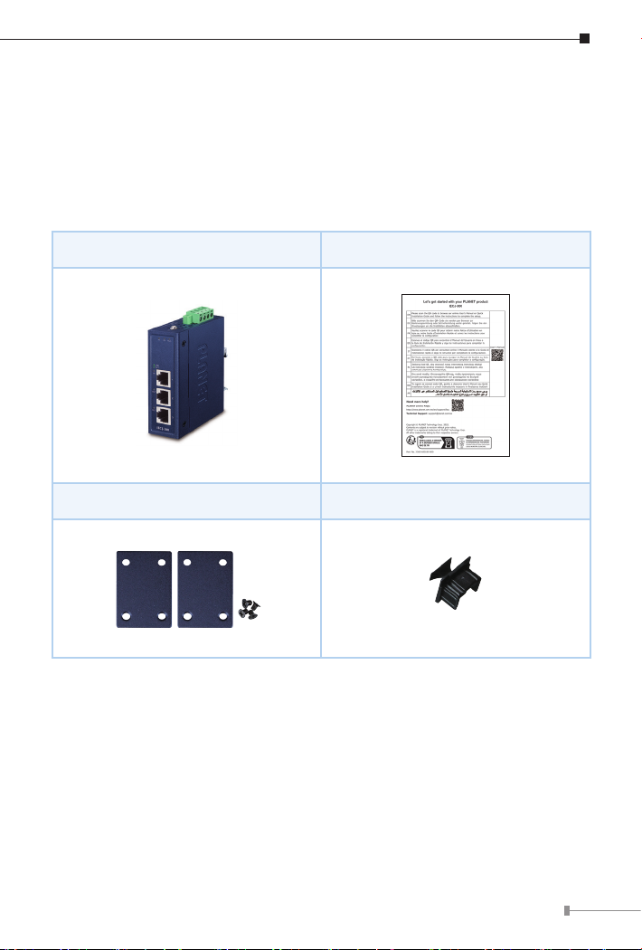
1. Package Contents................................................................................. 3
2. Product Features .................................................................................. 4
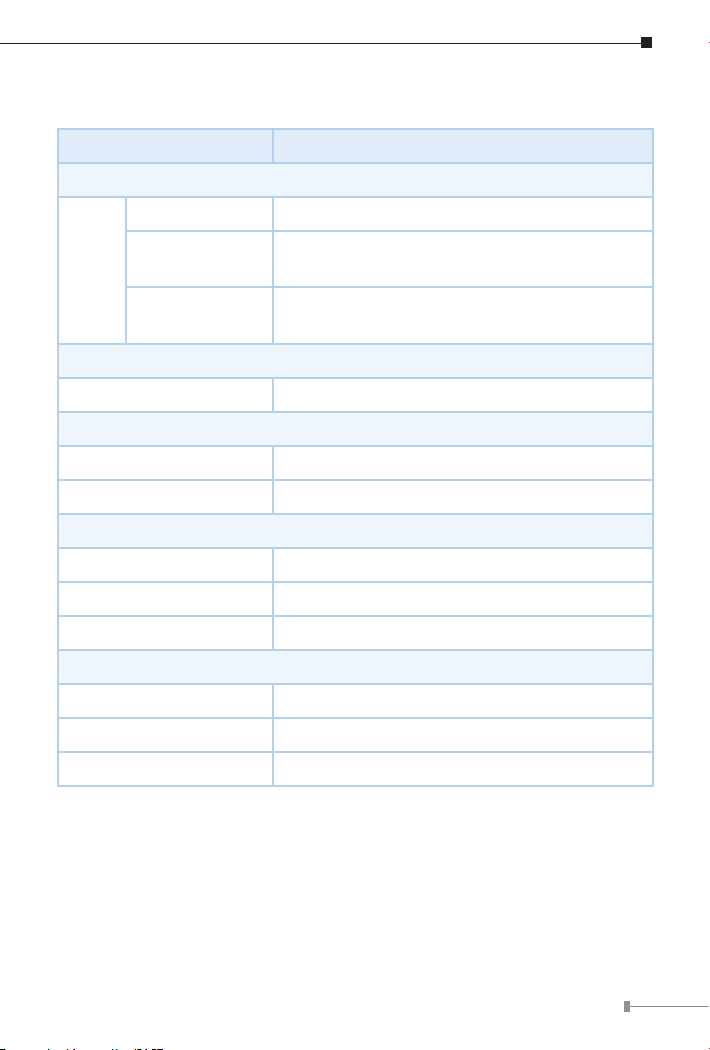
3. ProductSpecications ........................................................................... 5
4. Hardware Introduction .......................................................................... 6
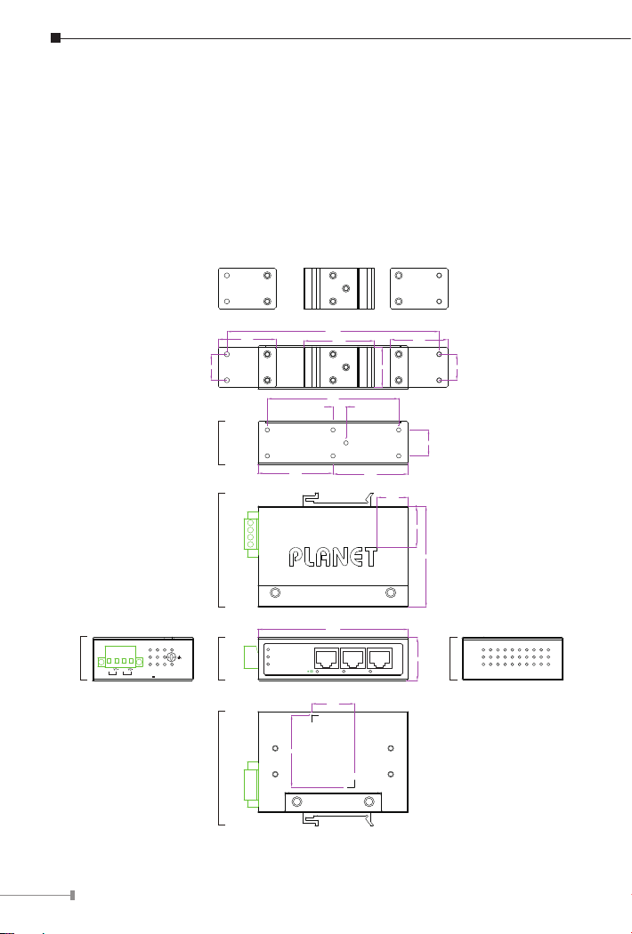
4.1 Three-View Diagram....................................................................... 6
4.2 Wiring the Power Inputs................................................................. 8
4.3 Grounding the Device ..................................................................... 9
5. Installation ........................................................................................ 10
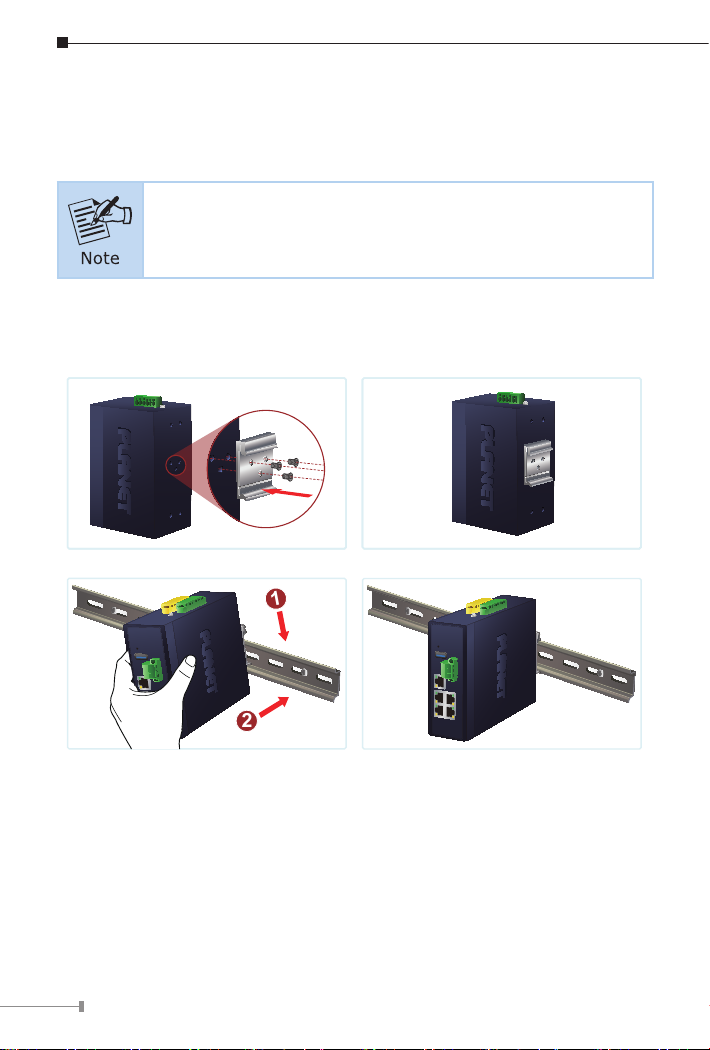
5.1 DIN-rail Mounting Installation ....................................................... 10
5.2 Wall-mount Plate Mounting ........................................................... 11
5.3 Side Wall-mount Plate Mounting.................................................... 11
6. Getting Started .................................................................................. 12
6.1 Connecting the Power and the Host PC.......................................... 12
6.2 CongurationandOperation ......................................................... 14
Customer Support.................................................................................... 16

3
1. Package Contents
Thank you for purchasing PLANET Industrial EtherCAT Junction Slave. In the
following sections, the term “Industrial EtherCAT Junction Slave” means
the IECJ-300.
Open the box of Industrial EtherCAT Junction Slave and carefully unpack it.
Theboxshouldcontainthefollowingitems:
IECJ-300x1 QRCodeSheetx1
Wall-mountKitx1 CopperDustCapx3
If any of these are missing or damaged, please contact your dealer
immediately; if possible, retain the carton including the original packing
material, and use them again to repack the product in case there is a need to
return it to us for repair.

4
2. Product Features
zThree100BASE-TXRJ45businterfaces
zLED indicators for the input status
zDual 9 ~ 48V DC wide input voltage range
zSupportsEtherCATdistributedclock(DC)mode
zEtherCATconformance testtoolveried

5
3.ProductSpecications
Model IECJ-300
Communication Interface
Copper
Port 3x100BASE-TXRJ45
Distancebetween
Stations max.100m(100BASE-TX)
Data Transfer
Medium ShieldedEthernet/EtherCATcable(min.cat5)
EtherCAT
Protocol EtherCAT
Power
Input Voltage Range Dual 9~48V DC
Power Consumption Maximum1.44W
Mechanical
Dimensions(WxDxH) 33x70x104mm
Installation DIN-rail mounting and wall mounting
Case Material IP30 metal
Environment
OperatingTemperature -40~75°C
Storage Temperature -40~85°C
Relative Humidity 5~95%(non-condensing)

6
4. Hardware Introduction
4.1 Three-View Diagram
The three-view diagram of the Industrial EtherCAT Junction Slave consists
of three 100BASE-TX RJ45 copper ports and one removable 4-pin power
terminal block. The LED indicators are also located on the front panel.
104.00
30.00
18.00
9.00
91.00
52.00 52.00
50.00
30.00
70.00
21.69
28.65
28.00
48.80 40.00
18.00
40.00
18.00
147.00
Mounting Kit
Mounting Kit
DIN-Rail Kit
Unit: mm
Rear ViewSide View Side View
Top View
Front View
Bottom View
IECJ-300
ACT
LNK
1
2
3
IN
OUT
OUT
P1 P2 Run
V2+
PWR2
V1+
PWR1
DC Input:
9-48V
, 0.6A max.
Figure 1: IECJ-300 Three-View Diagram

7
Front View
IECJ-300
ACT
LNK
1
2
3
IN
OUT
OUT
P1 P2 Run
Figure 2: IECJ-300 Front View
LED Denition:
System
LED Color Function
P1 Green Lights to indicate power 1 has power.
P2 Green Lights to indicate power 2 has power.
Run Green
Light The device is in the state of operation.
Single Flash The device is in the state of operation
without risk.
Blinking Thedeviceisreadytobeoperated.
O The device is in the initialization mode.

8
100BASE-TX RJ45 Port (Port Input/Port Output)
LED Color Function
LNK/ACT Green
Light Indicating that the port is linked up.
Blinking Indicating that the module is actively sending
or receiving data over that port.
O Indicating that the port is linked down.
4.2 Wiring the Power Inputs
The4-contactterminalblockconnectoron the top panel of Industrial EtherCAT
Junction Slave is used for two DC power input. Please follow the steps below
to insert the power wire.
When performing any of the procedures like inserting the wires
or tightening the wire-clamp screws, make sure the power is
OFFtopreventfromgettinganelectricshock.
1. Insert positive and negative DC power wires into contacts 1 and 2 or
contacts3and4forPOWER.
V2+
PWR2
V1+
PWR1
DC Input:
9-48V
, 0.6A max.
1 2 3 4
Figure 3: IECJ-300 Top View
2. Tighten the wire-clamp screws for preventing the wires from loosening.
1234
Power1 Power2
V1+ V1- V2+ V2-

9
1. The DC power input range is 9-48V DC.
2. The device provides input voltage polarity protection.
PWR1 and PWR2 must provide exactly the same DV voltage
forpowerloadbalancewhileoperatingwithdualpowerinput.
4.3 Grounding the Device
Users MUST complete grounding wired with the device; otherwise, a sudden
lightning could cause fatal damage to the device.
V2+
PWR2
V1+
PWR1
DC Input:
9-48V
, 0.6A max.
1 2 3 4
Earth Ground
EMD(Lightning)DAMAGEISNOTCOVEREDUNDERWARRANTY.

10
5. Installation
This section guides you to installing the Industrial EtherCAT Junction Slave on
theDINrailandwall.Pleasereadthischapter completelybeforecontinuing.
This following pictures show the user how to install the device,
and the device is not IECJ-300.
5.1 DIN-rail Mounting Installation
1
2

11
5.2 Wall-mount Plate Mounting
5.3 Side Wall-mount Plate Mounting
You must use the screws supplied with the wall-mounting
brackets. Damage caused to the parts by using incorrect screws
would invalidate your warranty.

12
6. Getting Started
This chapter provides a basic overview of how to congure and operate your
IECJ series.
6.1 Connecting the Power and the Host PC
Step 1: ConnectboththePort 1 of the IECJ-300 and RJ45 Ethernet port of
Host PC.
Ensurethat the network settings on the Host PC have been correctly
congured and are functioning normally. Ensure that the Windows
rewall and any anti-virus rewall is properly congured to allow
incomingconnections;ifnot,temporarilydisablethesefunctions.
Attaching an ESC (EtherCAT Slave Controller) directly to an
office network will result in network flooding, since the ESC will
reflect any frame – especially broadcast frames – back into the
network(broadcaststorm).
Step 2: Apply power to the IECJ-300
PC
V+
+
9-48V
DC
Connect the Host
device to the IN Port on
IECJ-300
Connect the V+ pin to positive
terminal on a 9-48V DC power
supply, and connect the V- pin to
the negative terminal.
V+
V+
IN

13
Step 3: Verify the “P1” LED indicator on the IECJ-300 module is Green;
“Port 1” LED indicator is Green.
Run
IECC-210T
ACTLNK
TP IN
SFP OUT
LNK/
ACT
100BASE-FX
IECJ-300
P1 P2
IN

14
6.2 Conguration and Operation
BeckhoTwinCAT3.x is themostcommonlyused EtherCATMastersoftware to
operate the IECJ-300.
ClickonthelinkbelowtodownloadBeckhoTwinCAT3.x:
https://www.beckho.com/en-en/support/download-nder/software-and-tools/
Inserting into the EtherCAT network
InstallationofthelatestXMLdevicedescription(ESI).
Make sure to use the latest installation description to install
the latest XML device. This can be downloaded from PLANET
website (https://www.planet.com.tw/en/support/downloads?&m
ethod=keyword&keyword=IECJ-300)and check the online FAQs
for the installation of the XML device.

15
Step 1: Automatic Scanning
zThe EtherCAT system must be in the safe, de-energized state before the
IECJ-300 module is connected to EtherCAT network.
zSwitchontheoperatingvoltage,openthe TwinCATSystemManaged(Cong
mode), and scan the devices as shown in the print screen instructions
below. Acknowledge all dialogs with “OK”, so that the conguration is in the
“FreeRun” mode.
Step 2: CongurationviaTwinCAT
Intheleft-handwindow of the TwinCATSystemManager,clickonthebrandof
the EtherCAT Box you wish to congure (Take the IECJ-300 for an example).
ClickBox1togetandcongurestate.

16
Customer Support
Thank you for purchasing PLANET products. You can browse our online FAQ
resource on PLANET web site rst to check if it could solve your issue. If you
need more support information, please contact PLANET switch support team.
PLANETonlineFAQs:
http://www.planet.com.tw/en/support/faq.php
Supportteammailaddress:
Copyright © PLANET Technology Corp. 2023.
Contentsaresubjecttorevisionwithoutpriornotice.
PLANET is a registered trademark of PLANET Technology Corp.
Allothertrademarksbelongto theirrespectiveowners.

17
FCC Warning
This device has been tested and found to comply with the limits for a Class
A digital device, pursuant to Part 15 of the FCC Rules. These limits are
designed to provide reasonable protection against harmful interference when
the equipment is operated in a commercial environment. This equipment
generates, uses, and can radiate radio frequency energy and, if not installed
and used in accordance with the Instruction manual, may cause harmful
interference to radio communications. Operation of this equipment in a
residential area is likely to cause harmful interference in which case the user
willberequiredtocorrecttheinterferenceathisownexpense.
CE Mark Warning
This device is compliant with Class A of CISPR 32. In a residential environment
thisequipmentmaycauseradiointerference.
WEEE Warning
To avoid the potential eects on the environment and human health
as a result of the presence of hazardous substances in electrical and
electronic equipment, end users of electrical and electronic
equipment should understand the meaning of the crossed-out
wheeledbinsymbol.DonotdisposeofWEEEas unsorted municipalwaste and
have to collect such WEEE separately.
Table of contents
Other Planet Recording Equipment manuals