3
Limits of use (IEC 60974-1)
The use of plasma equipment for cutting is typically discontinu-
ous as it consists of periods of effective operation (cutting) and
rest periods (while the piece is being positioned, etc.). The size
of the equipment is suitable for safe use of max. nominal cur-
rent I2 for a working time that is 40% of the total time of use.
The regulations in effect stipulate that 10 minutes is the maxi-
mum total time of use. For the work cycle, 40% of that time is
considered. Exceeding the permitted work cycle triggers the
intervention of a thermal protector which protects the inter-
nal components of the plasma cutting plant against dangerous
overheating. The intervention of the thermal protection is indi-
cated by powering on the yellow LED sited on the rack panel.
After a few minutes the thermal protection automatically re-
sets, the yellow LED goes off and the plant is ready for use
once again. This plant is built to have a protection level of IP
23 S, which means:
•
That it is protected against the penetration of solid foreign
bodies with diameters in excess of Ø 12 mm.
•
That it is protected against water spray hitting the surface
with an angle of incidence up to 60°.
•
That the plant has been tested for withstanding harmful ef-
fects due to water getting in when the moving parts on the
equipment are moving.
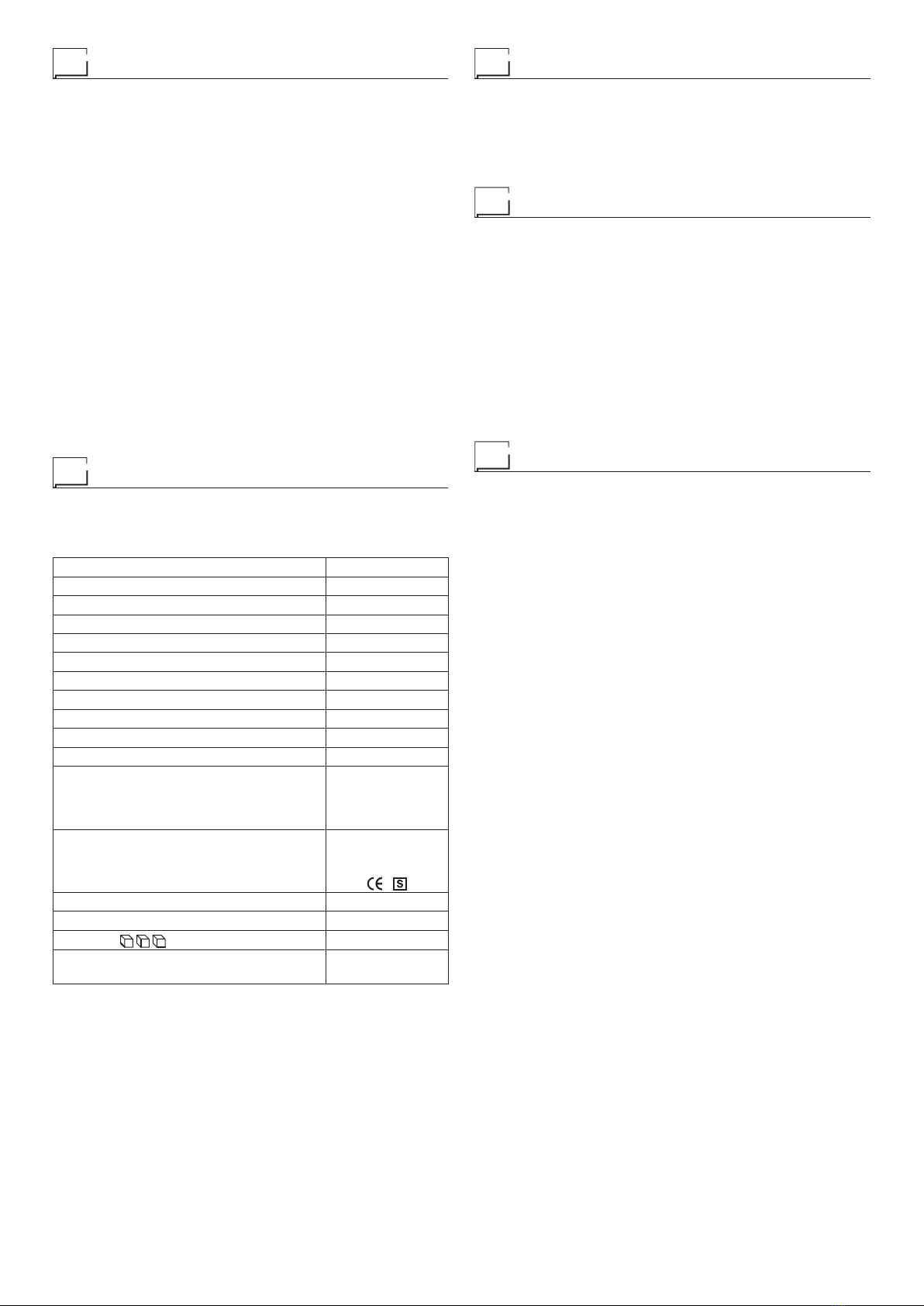
Technical data
The technical data for this equipment is summarized in the ta-
ble 1.
Table 1
Model SHARK 35
Single-phase power supply 50 Hz (*) V230
Mains supply: Zmax (**) Ω0,32
Power input @ I2Max kVA 6,05
Delayed fuse (I2@ 100%) A16
Power factor / cosφ 0,65 / 0,99
Maximum efficiency degree η0,71
Open circuit voltage (peak) V320
Current range A10 ÷ 30
Duty cycle @ 60% (40°C) A25
Duty cycle @ 40% (40°C) A30
Cutting capacity
recommended
maximum
severance
mm
mm
mm
8
10
15
Standards
IEC 60974-1
IEC 60974-7
IEC 60974-10
Insulation class IP 23 S
Protection class F
Dimensions mm 540-425-220
Plant weight
Plant weight including SK 25 torch kg 18,8
20,5
(*) special 60 Hz version by request.
(**) Mains supply Zmax: maximum impedance value allowed for
the grid according to the EN/IEC 61000-3-11 standard.
WARNING: This equipment does not comply with EN/IEC
61000-3-12. If it is connected to a public low voltage system, it
is the responsibility of the installer or user of the equipment to
ensure, by consultation with the distribution network operator
if necessary, that the equipment may be connected.
How to lift up the machine
This plant has a handle specifically for carrying the machine
by hand.
NOTE: These hoisting and transportation devices conform to
European standards. Do not use other hoisting and transpor-
tation systems.
Opening the packaging
The unit comprises the following main items:
• SHARK 35 plasma cutting unit.
•
Plasma torch with direct connector built into the plant, and
consumable “starting kit”.
• Earth cable.
• Trolley for transportation (optional).
On receipt of the unit, perform the following operations:
• Remove the plasma cutting unit and all relative accessories
and components from the packaging.
•
Check that the plasma cutting unit is in good condition. If it is
not, inform your dealer immediately.
•
Make sure that all the ventilation louvers are open and that
the airflow is not obstructed.
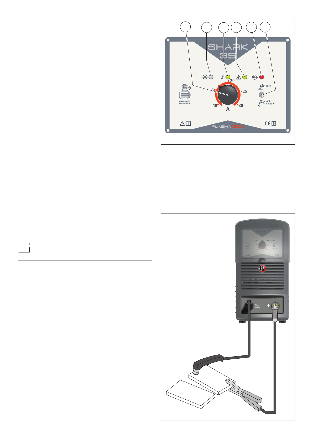
Plasma cutting
The cutting system used by this equipment is a low current sys-
tem that uses compressed air as its plasma equipment as well
as for cooling. The air normally used is a mixture of 79% nitro-
gen and 21% oxygen. These two biatomic gasses have almost
identical enthalpy and form a highly energetic blend. The low
current also makes it possible to use torches with a low air ca-
pacity and moderate cutting speed, that are more suitable for
manual procedures.
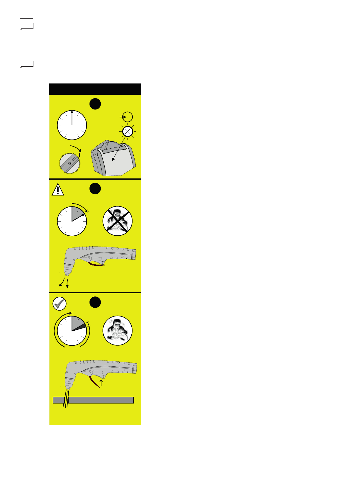
CUTTING PARAMETERS
In analyzing the parameters that characterize manual plasma
cutting it is necessary to note that they depend on the material
to be cut, its thickness and the skill of the operator in following
the cutting line. Optimum speed depends largely on the skill of
the operator and amount of material to be cut and is achieved
when the fused material flows through the groove and is not
projected in the direction of the torch. If the latter occurs, cut-
ting speed has to be reduced.
The parameters that affect cutting are:
•
Electric power. Any increase in electric power will permit
higher cutting speed and greater thickness of the material
to be cut
• Compressed air capacity. Increasing the air capacity ena-
bles cutting thicker material and ensures better quality at
any thickness
•
Distance between nozzle and piece. The appearance of the
cut and wear of the active components of the torch depends
on the nozzle being held as a correct distance from the piece.
NOTE: The width of the cutting groove is usually about twice
the diameter of the hole in the nozzle.
Respect of the above recommendations ensures greatly redu-
ced thermal alterations of the material due to cutting, that are in
any case always fewer than those caused by oxygen torches.
The thermally altered zone is in any case smaller than the zone
on which the weld is effective, so that in welding pieces that
have been cut by plasma it is not necessary to perform any
cleaning or grinding operations.