3
•
IP23S protection level and electronic parts protected against
dust, thanks to the innovative “tunnel” ventilation system,
which allows the unit to be used in the most problematic
working environments.
• Smart Start Transfer function, for better control over the ini-
tial cutting phase. Innovative electronic circuit that allows op-
timum, gradual transferring of the pilot arc to the main arc,
while the cutting arc is being ignited, ensuring immediate sta-
bility of the plasma flow and longer duration of consumables
used for the torch.
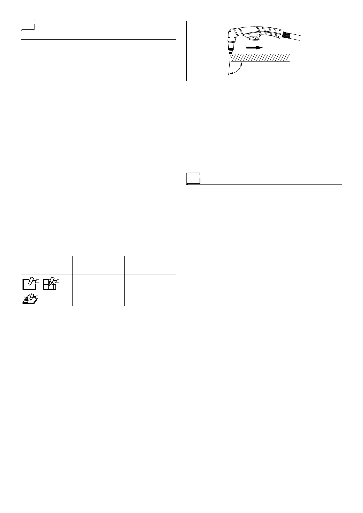
•
Smart End Cutting function, for better control over the final
cutting phase. Once cutting has been completed, the current
reaches an optimum value, which allows definitive detach-
ment of the pieces. In addition to reducing the noise when
cutting ends, this device means that the operator does not
have to separate the pieces manually, thereby ruining the fi-
nal portion of the cut surface.
SK and SKM torches
The SK and SKM torches, used with the SHARK machines,
are the result of research done over the last decade, aimed at
improving the performance of the plasma beam, in order to in-
crease control and thermal energy.
More specifically, the SK 165 and SKM 165 torches are charac-
terised by High Performance Cutting (HPC) technology, which
makes it possible to increase the quantity and speed of the air,
enhance concentration of the plasma beam, and stabilise the
cutting arc, which allows:
• High cutting speeds.
• Optimum quality and cleanliness of the cutting surfaces.
• High concentration of the Plasma beam.
• Absence of burrs.
• Reduction of the thermally altered zone.
• Longer lifespan for consumables.
• Piercing of plating more quickly.
•
Gouging to remove material with the help of a plasma beam.
All SK and SKM torches are fitted with a coaxial cable that en-
sures great flexibility, combined with significant strength and
resistance to crushing.
The High Performance Cutting - HPC technology, makes it
possible to generate radial and vortex gas flows about the arc’s
axis, thereby creating a Plasma beam at very high tempera
-
ture that pierces and vaporises the surface being worked more
efficiently.
This technology also makes it possible to avoid double arcs
from forming - two arcs in series between the cathode and the
workpiece’s surfaces - which is mainly responsible for damag-
ing the nozzle and instability of the arc - ensuring execution of
very high quality cuts, along with longer duration of consum-
ables.
Vortex gas flows and collimation of the beam
The new SK torches, equipped with High Performance Cut-
ting, increase the density of the Plasma beam’s energy, while
reducing the width of the arc’s area of action, producing a nar-
rower cut path, at less of an angle, easily removing molten
material. This results in a better quality cut that has neat sur-
rounding without burrs, a limited extent of the thermally altered
zone, and a sufficiently squared edge.
The main advantages include:
• Better cut quality.
• Higher cutting speed.
• Narrower cuts.
• Long duration of consumables.
CS - Original spare parts
CS is our guarantee mark for all PlasmaTECH consumables.
The CS mark is to be found on all original spare parts for SK
and SKM torches, used for the SHARK machines.
The presence of the CS mark on all consumables, is a guar-
antee for those buying a cutting machine, that the machine’s
declared performance levels will be delivered.
The geometric shapes, quality of the materials used, and preci-
sion of the machining and coupling of the same, resulting from
years of experience, form the basis for developing the SK and
SKM torches, and use of the same with our cutting generators.
We highly recommend the use of original spare parts marked
CS. In addition to compromising optimum function of the ma-
chine, using pirate parts could result in overheating and fluctu-
ations in electrical voltages, which is turn can cause:
• Overheating and damaging of the torch.
• Malfunctions and faults on the generator.
• Worsening of cut quality.
• Lessening of machine safety.
In light of the above, using any parts other than CS not only
causes the warranty on the machine to be null and void, but it
also means that CEA PlasmaTECH cannot be held responsi-
ble in case of any accidents.
Usage limits (IEC 60974-1)
The use of plasma equipment for cutting is typically disconti-
nuous as it consists of periods of effective operation (cutting)
and rest periods (while the piece is being positioned, etc.). The
size of the equipment is suitable for safe use of max. nominal
current I
2
for a working time that is 30% of the total time of use.
The regulations in effect stipulate that 10 minutes is the maxi-
mum total time of use. For the work cycle, 30% of that time is
considered. Any excess of the permitted work cycle triggers a
thermal circuit breaker which protects the internal components
of the equipment against dangerous overheating. Activation of
thermal protection is signaled by “t° C” flashing on control pan-
el display. After a few minutes the trip switch resets itself au-
tomatically and the cutting equipment is once again ready for
use. This equipment is built to have a protection level of IP 23
S, which means:
•
That it is protected against the penetration of solid foreign
bodies with diameters in excess of Ø 12 mm.
•
That it is protected against water spray hitting the surface
with an angle of incidence up to 60°.
• That the equipment has been tested for withstanding harm-
ful effects due to water getting in when the moving parts on
the equipment are moving.