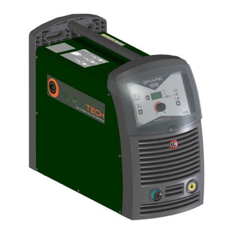
PLASMATECH SHARK 45 User manual

SHARK 45
1020HB83D-EN-09/2021 SN - CW xxxxxx
EN Operator’s manual READ CAREFULLY
CEA COSTRUZIONI ELETTROMECCANICHE ANNETTONI S.p.A.
C.so E. Filiberto, 27 - 23900 Lecco - Italy
Tel. ++39.0341.22322 - Fax ++39.0341.422646
Cas. Post. (P.O.BOX) 205

2
ENGLISH
EN
Introduction 2
Description 2
Usage limits (IEC 60974-1) 2
Technical data 3
How to lift up the machine 3
Opening the packaging 3
Plasma cutting 3
Installation 3
Connection to the electrical supply (Fig. A) 4
Usage norms 4
Connection of plasma torch and ground wire 5
Connection of compressed air 6
Sequence of operations to perform before cutting 6
Maintenance 7
Possible problems and remedies 7
Troubleshooting table 8
Common cutting defects 9
Meaning of graphic symbols on machine 9
Key to the electrical diagram 9
Colour key 9
Wiring diagram 10
Description
Powerful, light, and easy to manage, the SHARK 45 is an ef-
fective solution for manual cutting of any metal and perforated
plating. It is ideal for panel beating work, metalwork, industry
and maintenance tasks. It can be connected to a single-phase
power supply with a 16 A fuse, also and above all thanks to the
PFC (Power Factor Correction) device that makes the shape
of the wave of the current absorbed sinusoidal, resulting in an
absence of harmonic disturbance and optimisation of energy
absorption from the mains.
This plant’s technical characteristics are:
• Innovative practical design.
•
Supporting structure in metal with front panel in special
shockproof material.
• Robust handle integrated into the chassis.
• Arc parameter control device for excellent cutting quality.
• Single-phase power supply 230 V - 50/60 Hz (standard ver-
sion).
•
Double single-phase power supply 115/230 V - 50/60 Hz
(version on demand).
• Continuously regulated cutting current to improve the appe-
arance of the cut.
•
Stability of cutting parameters within ±15% of rated input volt-
age fluctuations.
•
Protection against under voltages and excess voltages on
the mains.
• Two position control:
- CUT - The switch must be moved to this position whenev-
er you want to cut.
-
AIR CHECK - The switch must be moved to this position
whenever you want to carry out a test to check that air is
present.
•
A series of LEDs for indicating the cutting operating cycle and
checking correct functioning of the plant.
•
Plasma torch with ignition of pilot arc without high frequency.
•
Accident prevention protection on the torch and in the equip-
ment complywith the new international safety norms.
• Heat protection against overloads.
• Low air consumption (130÷150 l/min @ 5÷5,5 bar).
• Air filter unit which automatically expels impurities.
Usage limits (IEC 60974-1)
The use of plasma equipment for cutting is typically disconti-
nuous as it consists of periods of effective operation (cutting)
and rest periods (while the piece is being positioned, etc.). The
size of the equipment is suitable for safe use of max. nominal
current I
2
for a working time that is 35% of the total time of use.
The regulations in effect stipulate that 10 minutes is the maxi-
mum total time of use. For the work cycle, 35% of that time is
considered. Any excess of the permitted work cycle triggers
a thermal circuit breaker which protects the internal compo-
nents of the equipment against dangerous overheating. When
the thermal circuit breaker is triggered, the yellow LED on the
front of the equipment is lit (Pos. 3, Fig. C). After a few min-
utes the overheat cutoff resets itself automatically and the yel-
low LED goes off, indicating that the equipment is once again
ready for use.
Introduction
Thank you for buying our product.
In order to get the best performance out of the plant and ensure
the maximum lifespan of its parts, the use and maintenance
instructions contained in this manual must be read and strictly
complied with, as well as the safety instructions contained
in the relevant folder. If repairs to the plant are required, we
recommend that our clients contact our service centre work-
shops, as they have the necessary equipment and personnel
that are specifically trained and constantly updated.
All our machines and equipment are constantly developed and
so changes may be made in terms of their construction and
features.

3
Technical data
The technical data for this equipment is summarized in the ta-
ble 1.
Table 1
Model SHARK 45
Single-phase power supply 50/60 Hz V115 ±15% 230 ±15%
Mains supply: Zmax Ω(*)
Power input @ I2Max kVA 4,8 5,5
Delayed fuse (I2@ 100%) A25 16
Power factor / cosφ 0,97 / 0,99
Efficiency degree η0,75 0,80
Open circuit voltage (peak) V460
Current range A20 ÷ 30 20 ÷ 40
Duty cycle @ 100% (40°C) A - 20
Duty cycle @ 60% (40°C) A20 30
Duty cycle @ 35% (40°C) A - 40
Duty cycle @ 25% (40°C) A30 -
Cutting capacity
recommended
maximum
severance
piercing
mm
mm
mm
mm
8
12
15
-
10
15
18
8
Standards
IEC 60974-1
IEC 60974-7
IEC 60974-10
Insulation class IP 23 S
Protection class F
Dimensions mm 595-390-185
Weight kg 15,50
(*) IMPORTANT:
•
This plant meets the requirements laid down in the EN/IEC 61000-
3-12 standard on harmonic currents.
•
This system, tested according to EN/IEC 61000-3-3, meets the re-
quirements of EN/IEC 61000-3-11.
How to lift up the machine
This plant has a handle specifically for carrying the machine
by hand.
NOTE: These hoisting and transportation devices conform to
European standards. Do not use other hoisting and transpor-
tation systems.
Opening the packaging
The standard composition of this plasma cutting system is
made up of:
• SHARK 45 cutting units.
•
Plasma torch with centralised attachment and spare parts kit.
• Earth cable, complete with rapid coupling.
• Neck strap (optional).
• Trolley for transportation (optional).
On receipt of the unit, perform the following operations:
• Remove the plasma cutting unit and all relative accessories
and components from the packaging.
•
Check that the plasma cutting unit is in good condition. If it is
not, inform your dealer immediately.
•
Make sure that all the ventilation louvers are open and that
the airflow is not obstructed.
Plasma cutting
The cutting system used by this equipment is a low current sys-
tem that uses compressed air as its plasma equipment as well
as for cooling. The air normally used is a mixture of 79% nitro-
gen and 21% oxygen. These two biatomic gasses have almost
identical enthalpy and form a highly energetic blend. The low
current also makes it possible to use torches with a low air ca-
pacity and moderate cutting speed, that are more suitable for
manual procedures.
CUTTING PARAMETERS
In analyzing the parameters that characterize manual plasma
cutting it is necessary to note that they depend on the material
to be cut, its thickness and the skill of the operator in following
the cutting line. Optimum speed depends largely on the skill of
the operator and amount of material to be cut and is achieved
when the fused material flows through the groove and is not
projected in the direction of the torch. If the latter occurs, cut-
ting speed has to be reduced.
The parameters that affect cutting are:
•
Electric power. Any increase in electric power will permit
higher cutting speed and greater thickness of the material
to be cut
• Compressed air capacity. Increasing the air capacity ena-
bles cutting thicker material and ensures better quality at
any thickness
•
Distance between hood and piece. The appearance of the
cut and wear of the active components of the torch depends
on the hood being held as a correct distance from the piece.
NOTE: The width of the cutting groove is usually about twice
the diameter of the hole in the hood.
Respect of the above recommendations ensures greatly redu-
ced thermal alterations of the material due to cutting, that are in
any case always fewer than those caused by oxygen torches.
The thermally altered zone is in any case smaller than the zone
on which the weld is effective, so that in welding pieces that
have been cut by plasma it is not necessary to perform any
cleaning or grinding operations.
Installation
The place where the equipment is installed should be selected
with care so as to ensure satisfactory, safe use.
The user is responsible for installation and use of the equip-
ment according to the instructions provided by the manufactu-
rer in this manual.
Temperatures must be between -20°C e +55°C. during tran-
sportation and/or storage in stores.
Before installing the equipment the user should take into con-
sideration any possible electromagnetic problems in the work
area.
In particular, we recommend that the equipment not be instal-
led in the vicinity of:
• Signalling, control and telephone cables.
• Radiotelevision transmitters and receivers.
• Computers or controlling and measuring instrument.
• Safety and protection devices.
If the operator wears a pacemaker, hearing aid or other sim-
ilar device, he should consult his doctor before approaching
the equipment while it is running. The environment where the
equipment is installed must conform with the degree of protec-
tion of the chassis that is IP 23 S (IEC publication 60529). The
system is capable of working in environments where working
conditions are particularly hard.
This equipment cools water by forced circulation of air and must
therefore be positioned in such a way that the air can easily
be drawn in and expelled through the openings in the chassis.
The air must be free of oil, moisture, and other pollutants. Oil
and excessive humidity may cause quick wear on consuma-
bles for the torch, or may even make it impossible to carry out
cutting operations. Other pollutants can cause poor cutting per-
formance and quick wear on consumables.

4
Connection to the electrical
supply (Fig. A)
Connection of the machine to the user line (electrical cur-
rent) must be performed by qualified personnel.
Before connecting the cutting equipment to the mains sup-
ply, check that the data on the machine plate correspond
to the supply voltage and frequency and its main switch
is on the “O” position (Pos. 1, Fig. A).
Connection to the power supply must be effected using the plug
provided with the cutting plant (Pos. 2, Fig. A).
Proceed as follows if you have to replace the plug:
•
2 conducting wires are needed for connecting the machine
to the supply
•
The third, which is YELLOW GREEN in colour is used for
making the “EARTH” connection.
Table 2 shows the capacity values that are recommended for
fuses in the line with delays.
Table 2
Model SHARK 45
Single-phase power supply 50/60 Hz V115 ±15% 230 ±15%
Power input @ I2Max kVA 4,8 5,5
Delayed fuse (I2@ 100%) A25 16
Duty cycle @ X% (40°C) A30 (25%) 40 (35%)
Mains supply connection cable
Length
Section
m
mm2
3
2,5
Earth cable
Length
Section
m
mm2
4
6
NOTE: If extensions of the power supply cable are used, they
must be of adequate cross section and never inferior to that of
the cable supplied.
Usage norms
COMMAND AND CONTROL DEVICES (Fig. B)
Pos. 1 Control panel (Fig. C).
Pos. 2 Snap-in connector for ground line.
Pos. 3 Centralised torch attachment.
Pos. 4 Power supply switch.
Pos. 5 Cutting plant power supply cable, complete with plug.
Pos. 6 Fast coupling to connect compressed air tube.
Pos. 7 Filter and cutting air pressure regulator. Adjust to
pressure of 5 bar. The air filter automatically expels
impurities.
Pos. 8 Pressure gauge for reading cutting air pressure.
1
32
4
5
6
7
8
FIG. B
1
2
FIG. A

5
CONTROL PANEL (Fig. C)
Pos. 1 Cutting current adjustment knob.
Pos. 2 White LED - power supply on. When on the system
is powered and ready for use.
Pos. 3 Yellow LED with dual function and protection: THER-
MOSTAT and OVERCURRENT.
• THERMOSTAT function: this LED shines to indi-
cate that the overheating protection has cut in be-
cause the work cycle is not being followed. After
several minutes the overheat cut-off rearms auto-
matically (and the yellow LED turns itself off) and
the welder is ready for use again.
•
OVERCURRENT function: this LED shines to
indicate that the overcurrent protection has cut in
because the current has reached hazardous lev-
els. The machine stops automatically. Switch off
the machine by turning the power supply switch
(Pos. 4, Fig. B) to position “O” and switch it on
again after at least 5 seconds.
Pos. 4 GENERAL WARNING SIGNAL yellow LED. This
switches on under the following conditions:
Switched on and flashing
•
External nozzle on the plasma torch missing or
screwed on incorrectly.
•
Consumables (external nozzle, hood, electrode,
etc.) on the plasma torch fitted incorrectly or worn.
•
In case of a faulty short-circuit on the plasma torch
between the electrode and the hood.
Switched on and steady
• No compressed air or insufficient pressure.
Pos. 5 Red PLASMA CUTTING CYCLE CHECK LED. This
LED switches on when the torch button is held down.
The plant is therefore ready for the cutting operation.
It switches off when the torch button is released.
Pos. 6 Two position control:
•
CUT - The switch must be moved to this position
whenever you want to cut.
•
AIR CHECK - The switch must be moved to this
position whenever you want to carry out a test to
check that air is present.
Connection of plasma torch
and ground wire
IMPORTANT: Before performing any operation regarding con-
nection of the torch and ground wire, disconnect the power to
the system.
IMPORTANT: Do not connect to the Plasma equipment any
other torch different from the standard supplied unes; the utili-
sation of other non suitable torches might be dangerous for
the operator.
Connect the plasma torch to the centralised unit as shown in
figure D, then screw the ring nut in place completely, until it is
completely closed.
To obtain elevated cutting quality, the torch must transform the
power generated by the plant into a high energy density plas-
ma jet, so that it can efficiently melt metal and guarantee suffi-
cient strength to remove the meted part from the cutting zone,
impeding the formation of burrs. The torch is this a fundamen-
tal, indispensable component of the plasma cutting plant.
The standard supplied Plasma torch has special CEA elec-
trical connections in the central adaptor. Before fitting a
new equipment, make sure that the torch central adaptor
electrical connectios are matching the ones of the Plas-
ma equipment.
Connect the earth cable to the rapid coupling on the positive
pole as indicated in figure D.
The ground wire has to be connected on the specific terminal
to the piece to be cut, which must be effectively grounded
as well as the cutting bench. Do not connect the ground ter-
minal to the piece of material to be removed.
WARNING: The work area must be free of oil, paint, and rust!
123456
FIG. C
FIG. D

6
Connection of compressed air
Connect the compressed air hose to the rapid coupling on the
back of the plant (Pos. 6, Fig. B). The system must be fed with
a constant flow of air at about 5 bar and with a minimum flow
capacity of 150 liters per minute.
If you have to use industrial compressed air in gas cylinders:
•
See the manufacturer’s specifications for the procedures for
installing and maintaining high pressure gas cylinders.
• Examine the valves on the cylinders to be sure that they are
clean and free of oil, grease, or any other foreign material.
• The cylinders must be fitted with a pressure regulator that is
able to provide feed pressures up to 6,9 bar and flows of at
least 150 lit/min.
Sequence of operations to
perform before cutting
IMPORTANT: Before switching on the equipment follow these
instructions carefully:
• Make sure the voltage and frequency of the supply network
correspond to the data on the rating plate.
• Make sure all the torch components are correctly installed.
•
Do not point the torch toward yourself or other persons near-
by. If switched on accidentally the pilot arc spark would ignite
and cause dangerous burns.
- 1 -
Turn the power supply switch (Pos. 4, Fig. B) to position 1.
- 2 -
The plant has just been started, and only the white LED that
shows that the mains power supply is on (Pos. 2, Fig. C) must
stay on the rack panel. The plant’s internal check runs a series
of programmed tests, during which the fan motor switches on
for a few seconds and air comes out of the torch.
- 3 -
Move the switch (Pos. 6, Fig. C) to the AIR CHECK position and
run the test to check that air is present (air pressure: 5-5,5 bar).
WARNING: The air comes out continuously!
- 4 -
Move the switch (Pos. 6, Fig. C) to the CUT position to be able
to begin cutting operations.
- 5 -
Adjust the electric current for cutting using the current regu-
lation knob (Pos. 1, Fig. C). Increasing the current will permit
higher speed cutting or, at the same speed, cutting of great-
er thickness.
- 6 -
Before starting to cut, effect a power on, moving the torch but-
ton protection upwards (Part A, Fig. E), and holding the torch
button down (Part B, Fig. E), for several seconds until the cut-
ting arc comes on. Avoid contact with the metallic item!
WARNING: After starting the plant or after the end of the post
airflow phase, the first time the pilot arc switches on this takes
more time for the plant to carry out the necessary electronic
and pneumatic tests.
- 7 -
To start cutting, press the torch button again, lighting the pi-
lot arc and starting air expulsion. During the cutting phase the
white LED that indicates that the power supply is on (Pos. 2,
Fig. C) and red LED that indicates that the plasma cutting cycle
check is running (Pos. 5, Fig. C) remain on on the rack panel.
FIG. G
FIG. F
FIG. E
CUTTING FROM THE EDGE OF A PIECE (Fig. F)
A) Position the torch, in a vertical position, on the external
edge of the item to be cut. In particular cases of extinction
of the arc at the entrance of the item to be cut, increase
the angle between the item and the metal by 95°.
B) Begin cutting from the external edge of the item until the
arc has fully traversed the same.
C) During the cut the nozzle may be kept in direct contract
with the item being cut. Do not hold the pilot arc on in the
air to avoid wasteful wear on the electrode and nozzle.
CUTTING FROM WITHIN AN ITEM (Fig. G)
A) Cut with the torch in an angular position with respect to the
item, the rotate slowly until perpendicular to the metal.
B) When sparks appear from the lower part of the item, this
indicates that the cutting arc has completely perforated the
item to be cut; The bore has been created and now the cut
can proceed. If the sparks and/or residues spray upwards,
this indicates that the torch is being moved too rapidly. Re-
duce cutting speed.
CUTTING WITH PROLONGED ITEMS
This technique is used to cut in poorly accessible positions such
as angles, hollows, channels, etc.
Consumables are used at a higher rate with this technique.
IMPORTANT: Precautions to be taken to cut correctly and ef-
ficaciously:
• Always cut moving the torch gently to achieve a stable, pre-
cise cut.
•
Always cut moving the torch towards you which is simpler
than cutting while pushing or moving away from yourself.
•
Do not press or apply pressure to the torch during cutting
operations.
• Always use a line of reference for straight cuts.
•
To execute circular cuts, we recommend application of the
specific compass (supplied upon request).
- 8 -
Completion of cutting operations. Wait for the air flow to cease
before powering off the plant. During this phase you may start
a new cutting cycle: press the button to restart the pilot arc.
- 9 -
Turn the power supply switch (Pos. 4, Fig. B) to position “O”,
thereby switching off the plant.

7
Maintenance
ATTENTION: Cut off the power supply to the equipment be-
fore effecting any internal inspection.
SPARE PARTS
Original spares have been specifically designed for our equip-
ment.
The use of spares that are not original may cause variations
in the performance and reduce the safety level of the equip
-
ment. We are not liable for damage due to use of spare parts
that are not original.
THE EQUIPMENT
As these systems are completely static except for the fan that
is, in any case, provided with self-lubricating bushes, only the
following operations are necessary:
•
Periodic removal of accumulations of dirt and dust inside the
equipment using compressed air.
•
Periodical inspection for worn cables or loose connections
that could cause overheating.
• Make sure the air circuit is completely free of any impurities
and that the connections are tight and free of any leaks. In
this regard, particular attention must be given to the solenoid
valve and the air filter.
•
Although the air filters do not have an automatic conden-
sate drain, it is good practice to clean the air filter insert from
time to time.
Possible problems and remedies
The power line is the cause of most problems. In case of break-
downs proceed as follows:
1) Check the line value of the voltage
2) Check that the power cable is perfectly fastened to the plug
and mains switch
3) Make sure the fuses are not burnt or loose
4) Check the following for defects:
• The switch that powers the machine
• The wall socket for the plug
• The equipment power switch
NOTE: Given the technical knowledge required for equipment
repair, we recommend, in case of faults, that you contact quali-
fied personnel or our technical support service.
TROUBLESHOOTING TABLE
It is normally possible to find the cause of a breakdown through
the 4 warning LEDS located on the right hand side of the front
of the system. The first thing to do, therefore, is to check which
leds are on. Here below we are listing some of the possible
breakdowns that may occur on the system.

8
Troubleshooting table
Defect Cause Remedy
White LED that indicates
that the power supply is
on (Pos. 2, Fig. C) is off
• Cutting plant power supply cable not
connected to the mains power supply
• Connect the cutting plant power supply
cable to the mains power supply
• Power supply switch (Pos. 4, Fig. B) off • Switch on the plant by turning the power
supply switch (Pos. 4, Fig. B) to position 1
• Mains voltage incorrect • Check that the voltage for the power
supply to the cutting plant corresponds to
that for the actual mains power supply
• Some components in the cutting plant
are defective or malfunctioning
• Call in technical assistance
Yellow LED (Pos. 3, Fig. C)
with dual function and
protection: THERMOSTAT
and OVERCURRENT
switched on
• THERMOSTAT function: when this
LED switches on it indicates that the
trip switch has tripped because you
are working beyond the work cycle
• After several minutes the overheat
cut-off rearms automatically (and
the yellow LED turns itself off) and
the welder is ready for use again
• OVERCURRENT function: this LED
shines to indicate that the overcurrent
protection has cut in because the
current has reached hazardous levels;
the machine stops automatically
• Switch off the machine by turning
the power supply switch (Pos. 4,
Fig. B) to position “O” and switch it
on again after at least 5 seconds
GENERAL WARNING
SIGNAL yellow LED (Pos. 4,
Fig. C) on and flashing
• External nozzle on the plasma torch
missing or screwed on incorrectly
• Fit the external nozzle on the plasma torch
or check that it is screwed on correctly
• Consumables (external nozzle,
hood, electrode, etc.) on the plasma
torch fitted incorrectly or worn
• Fit the consumables on the plasma torch
correctly and replace them if necessary
• In case of a faulty short-circuit on the plasma
torch between the electrode and the hood
• Check that the electrode and the
torch hood are fitted correctly
GENERAL WARNING
SIGNAL yellow LED (Pos. 4,
Fig. C) on and steady
• No compressed air or insufficient pressure • Check and replace the pressure
switch if necessary.
• Check the feed circuit for the compressed air
Lack of air with torch
button pressed
• Defective control board • Replace
• Defective solenoid valve • Replace
Pilot arc does not
go on when torch
button is pressed
• Defective control board • Replace
• Worn electrode and hood on torch • Replace
• Torch button defective • Replace
• Plasma torch connected
incorrectly or defectively.
• Check the plasma torch’s connection
and replace it if necessary.
Arc goes out on contact
with piece to be cut
• Lack of connection of ground wire • Connect ground wire

9
Common cutting defects
Defect Cause Remedy
Insufficient penetration • Cutting speed too high • Reduce speed
• Current too low • Increase current
• Ground wire connected wrong • Check ground wire connection
Main arc goes out • Cutting speed too slow • Increase speed
• Excessive erosion of electrode • Replace electrode
Excessive residues • Cutting speed too slow • Increase speed
• Hood hole eroded • Replace hood
Hood overheated or black • Current too high • Reduce current
• Space between hood and piece too small • Increase space
• Air dirty • Clean air filter
• Excessive erosion of electrode • Replace electrode
Pilot arc intermittent
or sparking
• Air dirty, greasy, wet • Clean air filter
• Pilot arc current too low • Check the equipment pilot arc circuit
Meaning of graphic symbols on machine
1 3 4 5 6 11
9 107 12 13 148
2
•1 Cutting current scale •2 Positive pole rapid coupling for earth wiring connection •3 System for use in environments with increased risk of electrocution
•4 White LED: signals power ON •5 Red LED: signals activation of torch button •6 Yellow LED for overheat cutoff •7 Yellow LED (generic power warning
signal) •8 Grounding protection •9 Dangerous voltage •10 Before using the equipment you should carefully read the instructions included in this manual •11
Warning! Risk of electric shock •12 Product suitable for free circulation in the European Community •13 Cut / air test switch •14 Centralised torch attachment
•1 •2 •3 •4 •5 •6 •7 •8 •9 •10 •11
BP BS CC1-2 CT DEL EVG IAP IL LLA
•12 •13 •14 •15 •16 •17 •18 •19 •20 •21 •22
LP LT LU MV PM POT1 PR PT RRP1-2 SC
•23 •24 •25 •26 •27 •28 •29 •30 •31 •32
SF SP ST SW1 TA TIP TP TPL TRP TRS
Key to the electrical diagram
•1 Primary transformer coil •2 Secondary transformer coil •3 Wiring inter-
face connectors •4 Torch connector •5 Secundary diodes •6 Torch elec-
trode •7 Air solenoid valve •8 IGBT pilot arc current control •9 Power supply
switch •10 Inductor •11 LED mains power supply on •12 LED various pro-
tective devices •13 Thermostat intervention LED •14 LED cutting power
supply on •15 Fan motor •16 Earth clip •17 Cutter voltage potentiometer
•18 Pressure switch •19 Torch button •20 Resistor •21 Primary rectifier •22
Control PCB •23 Front panel PCB •24 Inverter PCB •25 Protection on torch
•26 Cut / air test switch •27 Current transformer •28 Plasma torch hood
•29 Main transformer •30 Plasma torch •31 Primary circuit thermostat •32
Secondary circuit thermostat
Colour key
Ar Orange
Bc White
Bl Blue
Gg Grey
Gl Yellow
GV Yellow Green
Mr Brown
Nr Black
Rs Red
Vd Green
Vl Violet

10
Wiring diagram
2101EA58

SHARK 45
CEA COSTRUZIONI ELETTROMECCANICHE ANNETTONI S.p.A.
C.so E. Filiberto, 27 - 23900 Lecco - Italy
Tel. ++39.0341.22322 - Fax ++39.0341.422646
Cas. Post. (P.O.BOX) 205
IT Lista ricambi LEGGERE ATTENTAMENTE
EN Spare parts list READ CAREFULLY
FR Liste pièce de rechange LIRE ATTENTIVEMENT
DE Ersatzteilliste SORGFÄLTIG LESEN
ES Lista repuestos LEER ATENTAMENTE
NL Onderdelenlijst EERST GOED DOORLEZEN
PT Lista de peças de substituição LER ATENTEMENTE
DA Liste over reservedele LÆS OMHYGGELIGT
SV Reservdelslista LÄS NOGAS
FI Varaosaluettelo LUE HUOLELLISESTI
NReservedelliste LES NØYE
RU Список запасных частей
ПЕРЕД НАЧАЛОМ РАБОТЫ
ВНИМАТЕЛЬНО ПРОЧТИТЕ
ИНСТРУКЦИЮ

2
Pos. SHARK 45
230 V
SHARK 45
115/230 V Descrizione Description
1439398 439398A Adesivo regolazioni frontali Rack adjustment sticker
2438883 438883 Manopola corrente Current knob
3352453 352453 Visiera rack frontale Front rack transparent visor
4468191 468191 Logo CEA Sticker logo CEA
5352378 352378 Pannello frontale Front panel
6403608 403608 Attacco dinse polo positivo Quick connection positive polarity
7239630 239630 Cavo massa 4m Work cable and clamp
8468296 468296 Adesivo lato connessione torcia Plasma Sticker central connection Plasma torch side
9236621 236621 Attacco centralizzato torcia Plasma Central connection Plasma torch
10 461947 461947 Contatto femmina attacco
centralizzato (conf. 10 pz)
Female terminal for central
connector (pack 10 pcs)
11 022067 022067 Torcia Plasma SK65 4m Plasma torck SK65 4m
12 431329 431329 Piedino in gomma Rubber foot
IT Lista ricambi
EN Spare parts list
FR Liste pièces de rechange
DE Ersatzteilliste
ES Lista repuestos
NL Onderdelenlijst
PT Lista de peçãs de substituiçao
DA Liste over reservedele
SV Reservdelslista
FI Varaosaluettelo
NReservedelliste
RU Списокзапчастей
1
2
3
4
5
6
7
8
9
10
11
12

3
Pos. SHARK 45
230 V
SHARK 45
115/230 V Descrizione Description
13 468750 468750 Adesivo logo PLASMATECH Sticker logo PLASMATECH
14 438103 438103 Maniglia Handle
15 438710 438710 Manopola interruttore Main switch knob
16 432029 432029 Filtro regolatore Air filter
17 404370 404370 Attacco rapido ingresso aria compressa Air inlet nipple
18 438400 438400 Manometro Manometer
19 352377 352377 Pannello posteriore Rear panel
20 427895 427895 Pressacavo linea Main cable clamp
21 235942 235960 Cavo linea Main cable
22 420483 420483 Coperchio completo logo PLASMATECH Steel cover complete with logo
PLASMATECH stickers
23 468750 468750 Adesivo logo PLASMATECH Sticker logo PLASMATECH
13
14
15
16
17
18
19
20
21
22
23

4
Pos. SHARK 45
230 V
SHARK 45
115/230 V Descrizione Description
24 413452 413452 Cablaggio attacco centralizzato torcia Plasma Central connection Plasma torch wiring
25 425944 425944 Elettrovalvola Air solenoid valve
26 453249 453249 Pressostato Pressostat switch
27 404898 404898 Basamento metallico Steel base
28 449586 449586 Telaio interno metallico Steel internal chassis
29 455500 455500 Raddrizzatore primario Primary rectifier
30 435375 435375 Interruttore bipolare 1ph main switch
24
25
27
26
28
29
30

5
Pos. SHARK 45
230 V
SHARK 45
115/230 V Descrizione Description
31 485497 485497 Tubo rilsan Ø8 Ø8 rilsan hose
32 486373 486373 Ventilatore Fan
33 241267 241267 Assieme inverter di potenza Power inverter assembly
34 353055 353055 Isolamento scheda inverter
di potenza dal telaio
Power inverter electric insulation
from the chassis
35 377121 377121 Scheda elettronica controllo inverter Inverter control pcb
36 240241 240241 Induttanza principale Main inductance
37 481406 481406 Trasformatore principale Main transformer
38 240242 240242 Induttanza PFC PFC inductance
39 377122 377122 Scheda elettronica rack frontale Rack pcb
31
32
33
34
35
33
39
363738

6
IT Ordinazione dei pezzi di ricambio
Per la richiesta di pezzi di ricambio indicare chiaramente:
1) Il numero di codice del particolare
2) Il tipo di impianto
3) La tensione e la frequenza che rileverete dalla targhetta
dei dati posta sull’impianto
4) Il numero di matricola
ESEMPIO
N° 2 pezzi, codice n. 352419 - per l’impianto SHARK 45 -
115/230 V - 50/60 Hz - Matricola n° ........................................
EN Ordering spare parts
To ask for spare parts clearly state:
1) The code number of the piece
2) The type of device
3) The voltage and frequency read on the rating plate
4) The serial number of the same
EXAMPLE
N. 2 pieces code n. 352419 - for SHARK 45 - 115/230 V - 50/60
Hz - Serial number .......................................................
FR Commade des pièces de rechange
Pour commander des pièces de rechange indiquer clairement:
1) Le numéro de code de la pièce
2) Le type d’installation
3) La tension et la fréquence que vous trouverez sur la petite
plaque de données placée sur l’installation
4) Le numéro de matricule de la même
EXEMPLE
N. 2 pièces code 352419 - pour l’installation SHARK 45 -
115/230 V - 50/60 Hz - Matr. Numéro ....................................
DE Bestellung Ersatzeile
Für die Anforderung von Ersatzteilen geben Sie bitte deutlich
an:
1) Die Artikelnummer des Teiles
2) Den Anlagentyp
3) Die Spannung und Frequenz, die Sie auf dem Datenschild
der Anlage finden
4) Die Seriennummer der Schweißmaschine
BEISPIEL
2 Stück Artikelnummer 352419 - für Anlage SHARK 45 -
115/230 V - 50/60 Hz - Seriennummer ...................................
ES Pedido de las piezas de repuesto
Para pedir piezas de repuesto indiquen claramente:
1) El número de código del particular
2) El tipo de instalación
3) La tensión y la frequencia que se obtien de la chapa datos
colocada sobre la instalación
4) El número de matrícula de la soldadora misma
EJEMPLO
N. 2 piezas código 352419 - para instalación SHARK 45 -
115/230 V - 50/60 Hz - Matrícula N. .......................................
NL Bestelling van reserveonderdelen
Voor het bestellen van onderdelen duidelijk aangeven:
1) Het codenummer van het onderdeel
2) Soort apparaat
3) Spanning en frequentie op het gegevensplaatje te vinden
4) Het serienummer van het lasapparaat
VOORBEELD
N. 2 stuks code 352419 - voor apparaat SHARK 45 - 115/230 V
- 50/60 Hz - Serie Nummer ...................................
PT Requisição de peças sobressalentes
Ao pedir as peças de substituição indique claramente:
1) O número de código da peça
2) O tipo de equipamento
3) A tensão e a frequência indicadas na la placa de dados do
equipamento
4) O número de matrícula da própria máquina de soldar
EXEMPLO
N° 2 peças código n. 352419 - para o equipamento SHARK 45
- 115/230 V - 50/60 Hz
Matrícula n. ...............................
DA Bestilling af reservedele
For at bestille reservedele skal man nøjagtigt angive:
1) Reservedelens kodenummer
2) Anlæggets type
3) Spænding og frekvens, som står på anlæggets typeskylt
4) Selve svejsemaskinens registreringsnummer
EKSEMPEL
2 stk. nummer 352419 - til anlæg model SHARK 45 - 115/230 V
- 50/60 Hz
Registreringsnummer Nr. ..............................
SV Beställning af reservdelar
Vid förfrågan av reservdelar ange tydligt:
1) Detaljens kodnummer
2) Typ av apparat
3) Spänning och frekvens - den står bland tekniska data
påapparatens märkplåt
4) Svetsens serienummer
EXEMPEL
2 st. detaljer kod 352419 - för apparat SHARK 45 - 115/230 V
- 50/60 Hz - Serienummer ......................................
FI Varaosien tilaus
Tiedustellessanne varaosia, ilmoittakaa selvästi:
1) Osan koodinumero
2) Laitteiston tyyppi
3) jännite ja taaiuus, jokta on ilmoitettu laitteistolle sijoitetusta
tietokyltistä
4) Hitsauskoneen sarjanumero
ESIMERKKI
2 osaa, koodi 352419 - laitteistoon SHARK 45 - 115/230 V -
50/60 Hz - Sarjanumero ................................................
NBestilling av reservedeler
Ved bestilling av reservedeler må du oppgi:
1) Delenes kodenummer
2) Type apparat
3) Apparatets spenning og frekvens som finnes på
merkeplaten for data på apparatet
4) Sveiseapparatets serienummer
EKSEMPEL
2 stk. kode 352419 - for apparat SHARK 45 - 115/230 V - 50/60
Hz - Serienummer................................................
RU Заказзапасныхчастей
Для запроса запасных частей укажите точно:
1) код запчасти,
2) модель машины,
3) напряжение и частоту, написанные на пластине,
4) ее серийный номер.
ПРИМЕР
2 шт., код № 438401
n - штук деталей, код 352419, для сварочной машины
SHARK 25 230 B - 50/60 Hz
Серийный номер ..............................

CEA COSTRUZIONI ELETTROMECCANICHE ANNETTONI S.p.A.
C.so E. Filiberto, 27 - 23900 LECCO - ITALY
Cas. Post. (P.O. BOX) 205
Tel. +39 0341 22322 - Fax +39 0341 422646
www.ceaweld.com
Table of contents
Other PLASMATECH Welding System manuals
Popular Welding System manuals by other brands

Lincoln Electric
Lincoln Electric IDEALARC R3R-300 Operator's manual

EWM
EWM PHOENIX 301 EXPERT forceArc operating instructions

Jasic
Jasic TIG 200P Operator's manual

Telwin
Telwin CONVERTER 300 instruction manual

Westweld
Westweld RSR-2500 Manual instruction

Lincoln Electric
Lincoln Electric 9535 Operator's manual