IMPORTANT:
YOU MUST leave enough cable to
ensure it can reach to the furthest
point of the hot tub comfortable
from the isolator switch.
32 or 40 amp supply
1. Add 32 or 40 amp Type B Or C breaker
to the consumer unit (see image 1)
2. From the main consumer unit, run a 6mm, 3 Core
Armoured Cable to the Rotary Isolator Switch
(see image 2)
3. Rotary Isolator Switch should be 2-5m
from the hot tub (see image 3a)
4. The installing electrician will decide whether
an earth rod is needed or not
5. Another 6mm, 3 Core Armoured Cable must
be connected to the Rotary Isolator Switch with a
minimum of 10m worth of cable le in a loop. Our
delivery team are qualied to connect this cable to
the inside of the hot tub. However, they will NOT
hard-wire your hot tub to the mains supply
(see image 3b)
6. Your electrician should leave enough spare cable
aached to the isolator to reach the side panel
where the control panel is. More is beer than
not enough
7. A Part P cercate should be supplied by your
electrician. This is to conrm that the electrical
work is in line with government regulaons. This
paperwork must be kept on le and presented
when requested.
ELECTRICAL
REQUIREMENTS
Before installing a hot tub or swim spa, it is necessary to have your electrical supply ed.
You will require a 13, 32 or 40 amp supply (check with your supplier for the requirements for
a swim spa) depending on which model you have purchased. Electrical requirements vary on
each model, please check specicaons on individual spas.
Before your hot tub arrives, please arrange for a qualied electrician to do the following:
Posion isolator at least 2m
away from edge of hot tub,
where possible
Isolator Switch
Cable size is determined by the length of the run to
the hot tub. Mechanical protecon either SWA or
Conduct are required outdoors.
Consumer Unit
Hot Tub
2-5m
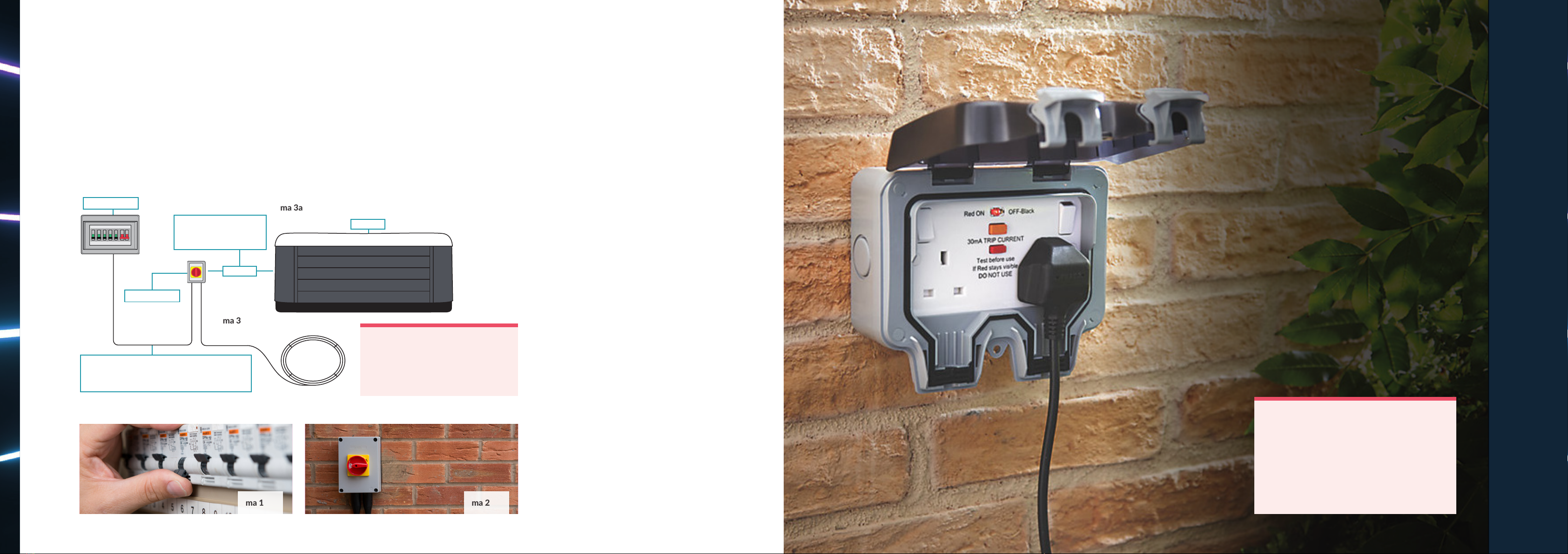
13 amp supply
A 13 amp hot tub will run o a standard 3 pin plug.
An electrician needs to conrm whether the hot
tub needs to have its own circuit from the main
distribuon board or if it can be used on another
socket circuit.
Please arrange for an electrician to do the
following before the delivery day:
1. Install a 13 amp outdoor waterproof
plug socket with RCD protecon. If an earth
rod is required, please seek advise from a
qualied electrician
2. Ensure the outdoor socket is within 2-5m
from the hot tub
3. Our 13amp hot tubs come with a 3m cable
so the hot tub needs to be 2m from the
power supply
4. If you would like your 13 amp hot tub run both
the heater and jets at the same me, it will
need to be rewired into the 32 amp power
unit. Please refer to the 32 amp installaon
guide for more informaon.
IMPORTANT:
The relevant steps must be completed before we
deliver your hot tub. Failure to do so will mean that
we cannot install your hot tub.
For 13, 32 and 40 amp supply hot tubs we
recommend your electrician installs an earth rod to
ensure the earthing systems voltage is the same as
the ground you are standing on. This will prevent
the voltage traveling through you and any ngling.
PREPARATION
| 9


 owner's manual")