Plexim plecs RT Box LaunchPad User manual

electrical engineering software
Plexim GmbH info@plexim.com www.plexim.com
PLECS User Manual Version 3.4
RT Box LaunchPad-Nucleo Interface
User Manual June 2023

How to Contact Plexim:
+41 44 533 51 00 Phone%
+41 44 533 51 01 Fax
Plexim GmbH Mail)
Technoparkstrasse 1
8005 Zurich
Switzerland
http://www.plexim.com Web
Revision History:
HW rev. 1.0 First release
HW rev. 1.1 Enhanced board size and improved
legend print
RT Box LaunchPad-Nucleo Interface
© 2023 by Plexim GmbH
PLECS is a registered trademark of Plexim GmbH. Other product or brand
names are trademarks or registered trademarks of their respective holders.

Contents
Contents iii
1 Introduction 1
2 Interface Board Overview 3
LaunchPadHeaders .............................. 4
Nucleo-64BoardHeaders ........................... 6
OnboardVoltageSupply............................ 7
AnalogOutput.................................. 8
DigitalI/O .................................... 8
Connectors.................................... 9
3 Appendix 11
LAUNCHXL-F280039C Pin Map . . . . . . . . . . . . . . . . . . . . . . . 12
LAUNCHXL-F280049C Pin Map . . . . . . . . . . . . . . . . . . . . . . . 15
LAUNCHXL-F28069M Pin Map . . . . . . . . . . . . . . . . . . . . . . . 18
LAUNCHXL-F28377S Pin Map . . . . . . . . . . . . . . . . . . . . . . . . 21
LAUNCHXL-F28379D Pin Map . . . . . . . . . . . . . . . . . . . . . . . . 24
LAUNCHXL-F28027 Pin Map . . . . . . . . . . . . . . . . . . . . . . . . . 27
STM32G4x Nucleo-64 Pin Map . . . . . . . . . . . . . . . . . . . . . . . . 29
STM32F3x Nucleo-64 Pin Map . . . . . . . . . . . . . . . . . . . . . . . . 32

Contents
iv

1
Introduction
The PLECS RT Box is a powerful real-time simulator based on a Xilinx Zynq
system on a chip (SOC). With its digital and analog I/O signals, the RT Box is
well-equipped for hardware-in-the-loop (HIL) testing as well as rapid control
prototyping (RCP).
If employed for HIL testing, the RT Box typically emulates the power stage
of a power electronic system. The power stage could be a simple DC/DC con-
verter, an AC drive system or a complex multi-level inverter system. The de-
vice under test (DUT) is the control hardware connected to the RT Box. In
such a setup, the complete controller can be tested without the real power
stage.
To simplify the connection of external hardware and to provide convenient ac-
cess to the RT Box inputs and outputs, Plexim offers a set of RT Box acces-
sories.
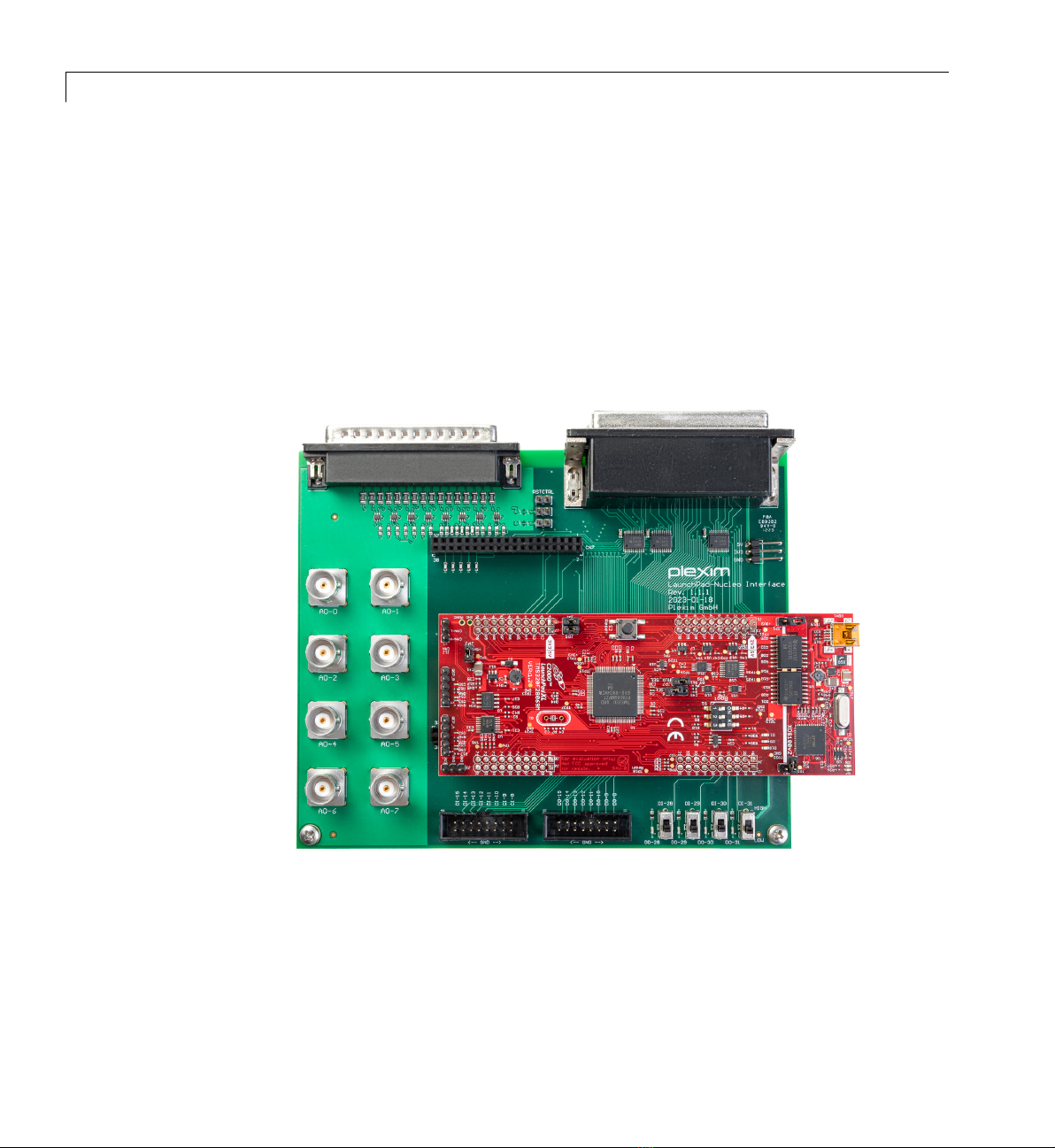
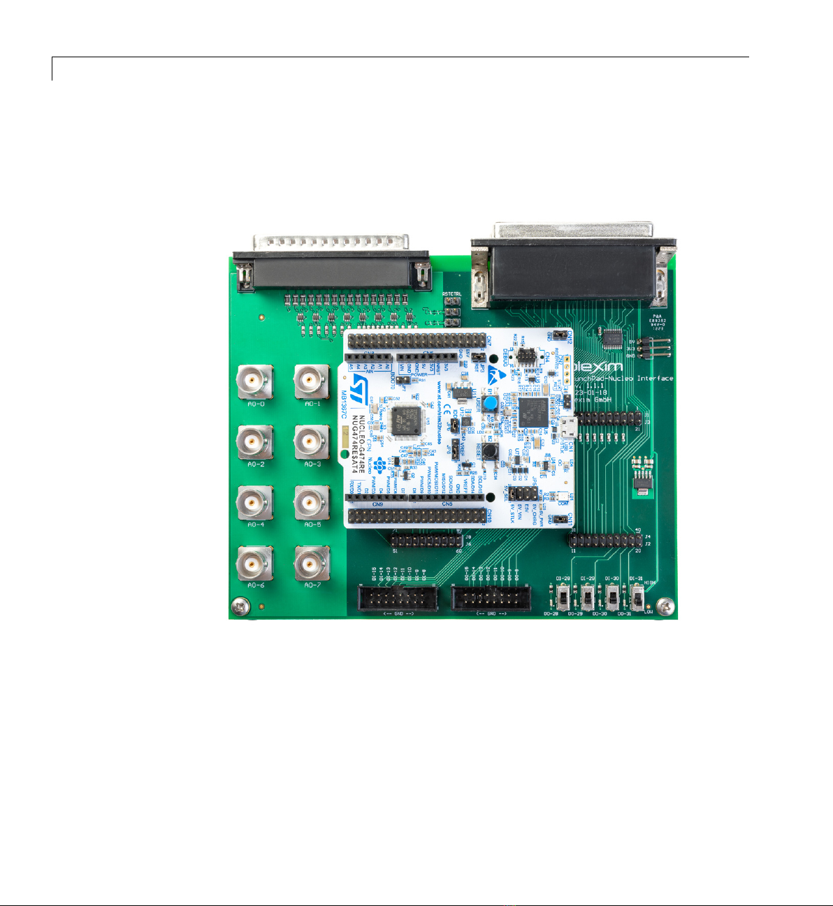
The RT Box LaunchPad-Nucleo Interface described in this document fa-
cilitates a simple connection of the RT Box with the LaunchPad or Launch-
Pad XL development kits from Texas Instruments, and Nucleo-64 development
boards from STMicroelectronics. It enables the user to test control algorithms
implemented on TI C2000 and STM32 MCUs without developing their own
interface hardware. The pinout of the LaunchPad-Nucleo Interface board has
been optimized for the following boards:
TI C2000 LaunchPads:
• LaunchXL-F280039C
• LaunchXL-F280049C
• LaunchXL-F28069M
• LaunchXL-F28377S
• LaunchXL-F28379D
• LaunchXL-F28027

1Introduction
STM32 Nucleo-64 boards:
• STM32G4 Nucleo-64
• STM32F3 Nucleo-64
The LaunchPad-Nucleo Interface can also be used with other LaunchPad or
Nucleo-64 boards not listed above, provided that the board physically aligns
and connects with the header pins. Users will need to create their own pin
assignment table, similar to the ones shown in Section 3.
2

2
Interface Board Overview
The LaunchPad-Nucleo Interface board facilitates the connection between a
TI C2000 LaunchPad, or an STM32 Nucleo-64 board and the RT Box. Fig. 2.1
shows the top view of the board without any MCU boards attached.
Figure 2.1: Top view of RT Box LaunchPad-Nucleo Interface
Additionally, the board provides access to some of the analog outputs of the

2Interface Board Overview
RT Box via BNC connectors, and to unused digital input and output signals
via shrouded pin headers. For simple status communication with the RT Box,
the board features four sliding switches and four LEDs.
LaunchPad Headers
A TI C2000 LaunchPad can be attached to the interface board using the cor-
responding pin headers. The LaunchPad will extend beyond the edge of the
interface board. Fig. 2.2 shows the correct mounting position.
Figure 2.2: RT Box LaunchPad-Nucleo Interface with LaunchXL-F28069M
Tables 2.1 and 2.2 list the pin assignments of the LaunchPad headers and the
RT Box signals. NC denotes no connection.
A more detailed table including the available processor functions at each pin
for the supported LaunchPads can be found in the appendix.
4

LaunchPad Headers
RT Box J1 J3 RT Box
+3.3 V 1 21 NC
NC 2 22 GND
DO-0 3 23 AO-0
DO-1 4 24 AO-1
DO-2 5 25 AO-2
NC 6 26 AO-3
DI-24 7 27 AO-4
DI-25 8 28 AO-5
DI-26 9 29 AO-6
DO-27 10 30 AO-7
RT Box J4 J2 RT Box
DI-0 40 20 GND
DI-1 39 19 DI-6
DI-2 38 18 DI-7
DI-3 37 17 NC
DI-4 36 16 RESET (DO-25)
DI-5 35 15 DI-27
DO-4 34 14 DO-26
DO-5 33 13 DO-6
NC 32 12 DO-7
NC 31 11 DO-3
Table 2.1: LaunchPad header pins - J1, J3, J4, J2
RT Box J5 J7 RT Box
+3.3 V 41 61 NC
NC 42 62 GND
DO-16 43 63 AO-8
DO-17 44 64 AO-9
DO-18 45 65 AO-10
NC 46 66 AO-11
NC 47 67 AO-12
DO-19 48 68 AO-13
NC 49 69 AO-14
NC 50 70 AO-15
RT Box J8 J6 RT Box
DI-16 80 60 GND
DI-17 79 59 DI-22
DI-18 78 58 DI-23
DI-19 77 57 NC
DI-20 76 56 NC
DI-21 75 55 DO-20
NC 74 54 DO-21
NC 73 53 DO-22
NC 72 52 DO-23
NC 71 51 DO-24
Table 2.2: LaunchPad header pins - J5, J7, J8, J6
5

2Interface Board Overview
Nucleo-64 Board Headers
An STM32 Nucleo-64 development board can be attached to the interface
board using the corresponding pin headers, as shown in Fig. 2.3.
Figure 2.3: RT Box LaunchPad-Nucleo Interface with Nucleo-G474RE
Tables 2.3 and 2.4 list the pin assignments of the Nucleo-64 board headers
and the RT Box signals. NC denotes no connection.
A more detailed table including the available processor functions at each pin
for the supported Nucleo-64 boards can be found in the appendix.
6

Onboard Voltage Supply
RT Box CN7 RT Box
DO-27 1 2 DI-24
DO-26 3 4 DI-25
NC 5 6 +5 V
NC 7 8 GND
NC 9 . . . 12 NC
NC 13 14 RESET (DO-25)
NC 15 16 +3.3 V
DO-0 17 18 NC
GND 19 20 GND
RT Box CN7 RT Box
DO-16 21 22 GND
DI-26 23 24 NC
DO-18 25 26 NC
DO-19 27 28 AO-0
NC 29 30 AO-1
NC 31 32 AO-2
NC 33 34 AO-3
AO-6 35 36 AO-4
AO-7 37 38 AO-5
Table 2.3: Nucleo-64 board header pins - CN7
RT Box CN10 RT Box
DI-6 1 2 DI-20
DO-3 3 4 DI-16
DI-23 5 6 AO-8
NC 7 8 NC
GND 9 10 NC
DI-27 11 12 DO-20
DO-1 13 14 DI-7
DI-17 15 16 DI-22
DO-21 17 18 AO-9
RT Box CN10 RT Box
DI-18 19 20 GND
DI-2 21 22 DO-22
DI-0 23 24 AO-10
DO-23 25 26 DI-5
DI-19 27 28 DI-3
DI-21 29 30 DI-1
DO-24 31 32 GND
DI-4 33 34 NC
NC 35 . . . 38 NC
Table 2.4: Nucleo-64 board header pins - CN10
Onboard Voltage Supply
The LaunchPad board is powered from the interface board, no external power
supply is required. The interface board contains a linear voltage regulator
7

2Interface Board Overview
that converts the 5 V supplied by the RT Box down to 3.3 V as required.
The Nucleo-64 board can also be powered from the interface board, since pin
CN7-6, labeled “E5V” on the Nucleo-64 board, is supplied with 5 V from the
RT Box. Set Jumper JP5 labeled “5V_SEL” to “E5V” on the Nucleo-64 board
for the board to be powered by the RT Box.
Both supply voltages 5 V and 3.3 V are accessible at a 3-pin header on the in-
terface board if the user wants to power external circuits. The maximum load
for both voltage levels combined is 1.5 A. When an external circuit requires
a 5 V supply it is recommended to draw the required power from the 3-pin
header on the interface board and not from the LaunchPad or the Nucleo-64
board, to minimize losses and component stress.
Analog Output
The interface board connects all 16 analog outputs from the RT Box to the
LaunchPad and Nucleo-64 headers. The lower 8 channels, AO-0 . . . AO-7, are
also accessible via the BNC connectors.
To limit the current flowing through the DAC op-amps in the RT Box, a 92.9-
ohm resistor is placed in series with each analog output channel. Further-
more, to safeguard the MCU inputs from overvoltage, each analog output
channel is clamped to 0 V and 3.3 V with two Schottky diodes.
Digital I/O
Not all the digital inputs and outputs of the RT Box are connected to the
LaunchPad or Nucleo-64 board headers. The unused digital inputs, DI-8 . . . DI-
15, and outputs, DO-8 . . . DO-15, are freely accessible at the shrouded headers
on the lower side of interface board. The digital outputs DO-28 . . . DO-31 are
connected to four orange LEDs in the lower right corner of the board. The dig-
ital inputs DI-28 . . . DI-31 can be set via four sliding switches.
All other digital inputs and outputs from the RT Box are connected to the
LaunchPad and Nucleo-64 board headers. To protect the inputs of the MCU
from voltages greater than 3.3 V, the corresponding outputs of the RT Box are
buffered with bus transceivers.
DO-25 is connected to the MCU reset pin via the RST jumper. If the jumper
is set, a low-level output at DO-25 will reset the MCU. Do not set this jumper
unless you wish to use this feature.
8

Connectors
Connectors
The following table contains the part numbers of the connectors used on the
LaunchPad-Nucleo interface board. For dimensions of the front panel of the
RT Box, refer to the RT Box manual.
Manufacturer Part Number Function
Sullins PRPC010DAAN-RC 20-pin LaunchPad headers
Sullins PPPC192LFBN-RC 38-pin Nucleo-64 headers
3M 961103-5604-AR 3-pin header to access 5 V and 3.3 V
Radiall R141426161 BNC connector to access analog outs 0-7
On Shore Technology 302-S161 16-pin headers to access digital I/O 8-15
Assmann A-DS 37 A/KG-T4S 37-pin DSUB to connect to RT Box Analog Out
Assmann ASUB-277-37TP25 37-pin DSUB stacked to connect to RT Box Digital I/O
Table 2.5: Connectors on the LaunchPad-Nucleo Interface
9

2Interface Board Overview
10

3
Appendix
The tables on the next pages provide more detailed information on the connec-
tivity of the LaunchPad-Nucleo Interface. For each TI C2000 LaunchPad and
STM32 Nucleo-64 board, the RT Box I/O is shown beside the header pins, and
the processor peripherals available at those pins. Note that not all peripher-
als are listed. Refer to the datasheet of the MCU board for a complete list of
available peripherals. NC denotes no connection.

3Appendix
LAUNCHXL-F280039C Pin Map
Table 3.1: F280039C LaunchPad Pin Map - J1, J3
MCU Function RT Box J1 J3 RT Box MCU Function
3.3 V power supply +3.3 V 1 21 NC
NC 2 22 GND
GPIO28, SCIA_RX DO-0 3 23 AO-0 ADCINA6
GPIO29, SCIA_TX DO-1 4 24 AO-1 ADCINA2/B6/C9
DO-2 5 25 AO-2 ADCINA3/B9/C7
NC 6 26 AO-3 ADCINA14/B14/C4
GPIO9, EPWM5B, SPIA_CLK DI-24 7 27 AO-4 ADCINA11/B10/C0
GPIO24, BOOT1 DI-25 8 28 AO-5 ADCINB12/C2
GPIO51, I2CB_SCL DI-26 9 29 AO-6 ADCINA7/C3
GPIO34, I2CB_SDA DO-27 10 30 AO-7 ADCINA1/B7
Table 3.2: F280039C LaunchPad Pin Map - J5, J7
MCU Function RT Box J5 J7 RT Box MCU Function
3.3 V power supply +3.3 V 41 61 NC
NC 42 62 GND
GPIO15, SCIB_RX DO-16 43 63 AO-8 ADCINB11
GPIO56, SCIB_TX DO-17 44 64 AO-9 ADCINA10/B1/C10
DO-18 45 65 AO-10 ADCINA5
NC 46 66 AO-11 ADCINA4/B8
NC 47 67 AO-12 ADCINB4/C8
GPIO4, CANA_TX DO-19 48 68 AO-13 ADCINB5
12

LAUNCHXL-F280039C Pin Map
Table 3.2: F280039C LaunchPad Pin Map - J5, J7 (continued)
MCU Function RT Box J5 J7 RT Box MCU Function
NC 49 69 AO-14 ADCINA12/C5
NC 50 70 AO-15 ADCINA0/B15/C15, DACA_OUT
Table 3.3: F280039C LaunchPad Pin Map - J4, J2
MCU Function RT Box J4 J2 RT Box MCU Function
GPIO0, PWM1A DI-0 40 20 GND
GPIO1, PWM1B DI-1 39 19 DI-6 GPIO5, SPIA_STE, CANA_RX
GPIO2, PWM2A DI-2 38 18 DI-7 GPIO32, BOOT2
GPIO3, PWM2B DI-3 37 17 NC
GPIO10, PWM6A DI-4 36 16 DO-25 RESET
GPIO11, PWM6B DI-5 35 15 DI-27 GPIO8, EPWM5A, SPIA_SIMO
GPIO33 DO-4 34 14 DO-26 GPIO17, SPIA_SOMI
GPIO48 DO-5 33 13 DO-6 GPIO37, EQEP1B
NC 32 12 DO-7 GPIO22, LED5
NC 31 11 DO-3 GPIO23, EQEP1I
Table 3.4: F280039C LaunchPad Pin Map - J8, J6
MCU Function RT Box J8 J6 RT Box MCU Function
GPIO12, PWM7A DI-16 80 60 GND
GPIO13, PWM7B DI-17 79 59 DI-22 GPIO27, SPIB_STE
GPIO6, PWM4A DI-18 78 58 DI-23 GPIO47
GPIO7, PWM4B DI-19 77 57 NC
13

3Appendix
Table 3.4: F280039C LaunchPad Pin Map - J8, J6 (continued)
MCU Function RT Box J8 J6 RT Box MCU Function
GPIO16, PWM5A DI-20 76 56 NC
GPIO35, PWM5B DI-21 75 55 DO-20 GPIO60, SPIB_SIMO
NC 74 54 DO-21 GPIO61, SPIB_SOMI
NC 73 53 DO-22 GPIO20, LED4
NC 72 52 DO-23 GPIO26
NC 71 51 DO-24 GPIO25, EQEP1A
14

LAUNCHXL-F280049C Pin Map
Table 3.5: F280049C LaunchPad Pin Map - J1, J3
MCU Function RT Box J1 J3 RT Box MCU Function
3.3 V power supply +3.3 V 1 21 NC
NC 2 22 GND
GPIO13 DO-0 3 23 AO-0 ADCINA5
GPIO40 DO-1 4 24 AO-1 ADCINB0
DO-2 5 25 AO-2 ADCINC2
NC 6 26 AO-3 ADCINB1
GPIO56, SPICLKA DI-24 7 27 AO-4 ADCINB2
ADCINC4 DI-25 8 28 AO-5 ADCINC0
GPIO37, EQEP1B DI-26 9 29 AO-6 ADCINA9
GPIO35, EQEP1A DO-27 10 30 AO-7 ADCINA1
Table 3.6: F280049C LaunchPad Pin Map - J5, J7
MCU Function RT Box J5 J7 RT Box MCU Function
3.3 V power supply +3.3 V 41 61 NC
NC 42 62 GND
GPIO28, EQEP1A DO-16 43 63 AO-8 ADCINA6
GPIO29, EQEP1B DO-17 44 64 AO-9 ADCINB6
ADCINB4 DO-18 45 65 AO-10 ADCINC14
NC 46 66 AO-11 ADCINC1
NC 47 67 AO-12 ADCINC3
ADCINA8 DO-19 48 68 AO-13 ADCINC5
15

3Appendix
Table 3.6: F280049C LaunchPad Pin Map - J5, J7 (continued)
MCU Function RT Box J5 J7 RT Box MCU Function
NC 49 69 AO-14 ADCINA3
NC 50 70 AO-15 ADCINA0
Table 3.7: F280049C LaunchPad Pin Map - J4, J2
MCU Function RT Box J4 J2 RT Box MCU Function
GPIO10, EPWM6A, EQEP1A DI-0 40 20 GND
GPIO11, EPWM6B, EQEP1B DI-1 39 19 DI-6 GPIO57, SPISTEA
GPIO8, EPWM5A DI-2 38 18 DI-7
GPIO9, EPWM5B, EQEP1I,
OUTXBAR6
DI-3 37 17 NC
GPIO4, EPWM3A DI-4 36 16 DO-25 RESET
GPIO5, EPWM3B, OUTXBAR3 DI-5 35 15 DI-27 GPIO16, SPISIMOA
GPIO58, OUTXBAR1 DO-4 34 14 DO-26 GPIO17, SPISOMIA
GPIO30, OUTXBAR7 DO-5 33 13 DO-6 GPIO39
NC 32 12 DO-7 GPIO23
NC 31 11 DO-3 GPIO59, EQEP1I
Table 3.8: F280049C LaunchPad Pin Map - J8, J6
MCU Function RT Box J8 J6 RT Box MCU Function
GPIO0, EPWM1A DI-16 80 60 GND
GPIO1, EPWM1B DI-17 79 59 DI-22 GPIO27, SPISTEB
GPIO6, EPWM4A DI-18 78 58 DI-23
16
Table of contents