Plockmatic TR5010e User manual

TRIMMER TR5010e
SERVICE MANUAL
4 August 2009
Subject to change

Page intentionally blank

III
4 August 2009
TABLE OF CONTENTS
1 INSTALLATION PROCEDURE
1.1 INSTALLATION PROCEDURE...........................................................TR-1-1
2 PREVENTIVE MAINTENANCE SCHEDULE
2.1 PREVENTIVE MAINTENANCE SCHEDULE .....................................TR-2-1
3. REPLACEMENT AND ADJUSTMENT
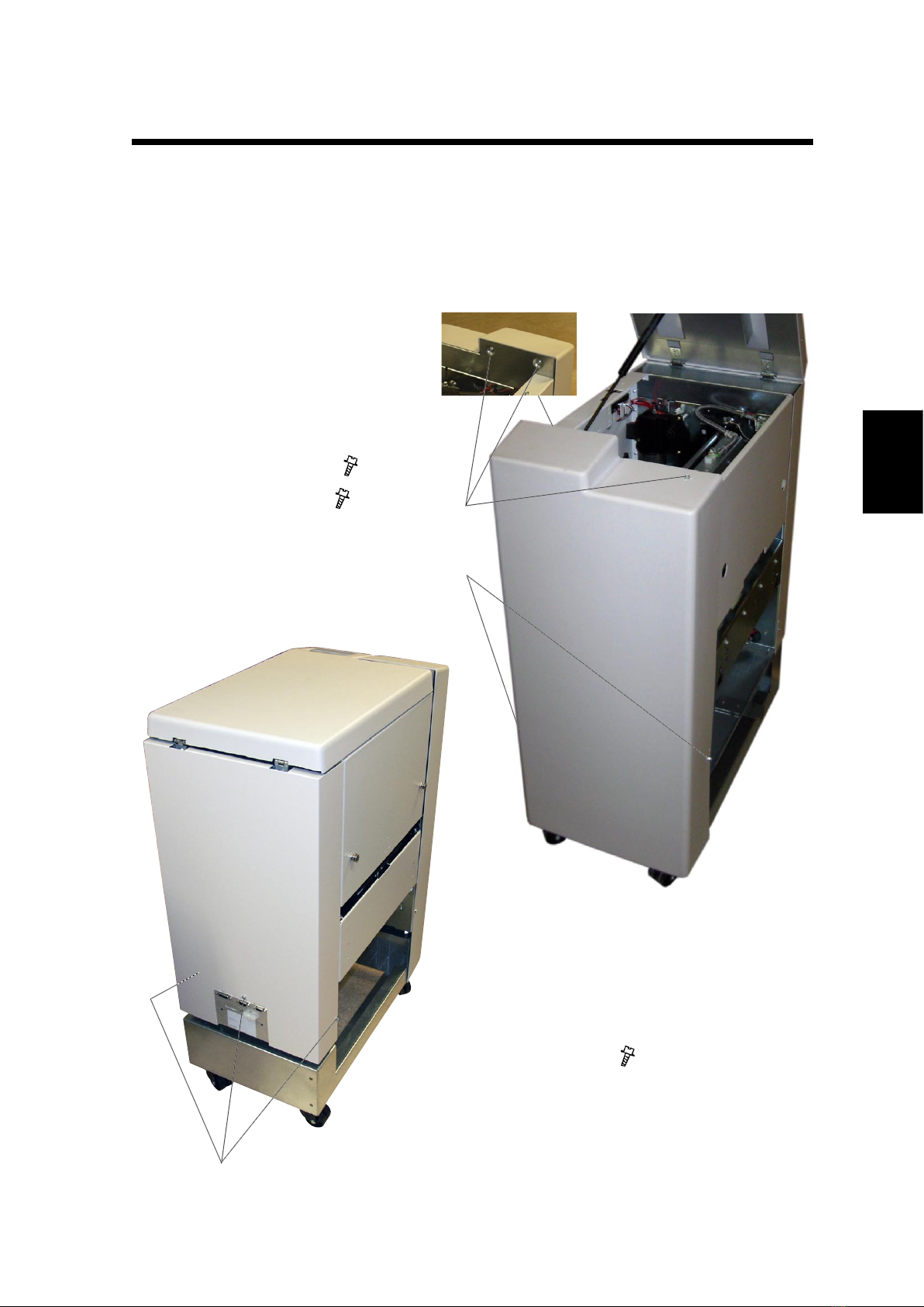
3.1 COVERS.............................................................................................TR-3-1
3.1.1 FRONT AND REAR COVER.....................................................TR-3-1
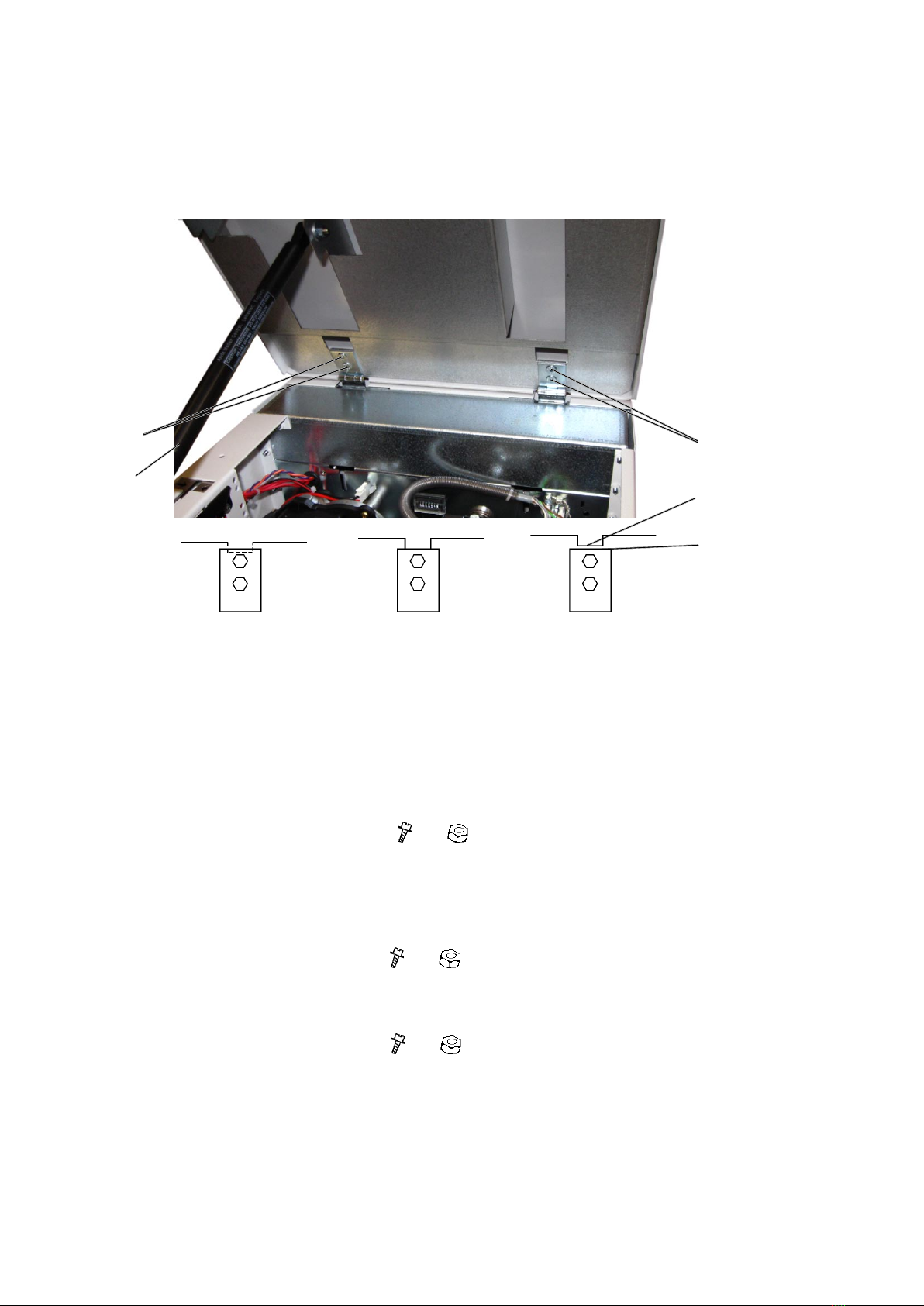
3.1.2 TOP COVER .............................................................................TR-3-2
3.1.3 BLOWER MOTOR M5 / M6.......................................................TR-3-3
3.1.4 INFEED COVER........................................................................TR-3-4
3.1.5 LOCKING BRACKET ................................................................TR-3-5
3.1.6 UPPER OUTFEED COVER ...................................................... TR-3-6
3.1.7 INTERLOCK SWITCH S9 &S10................................................TR-3-7
3.1.8 LOWER OUTFEED COVER ..................................................... TR-3-8
3.1.9 PROTECTION COVER ............................................................. TR-3-9
3.1.10 INTERLOCK MECHANISM.....................................................TR-3-10
3.2 AREA C............................................................................................. TR-3-11
3.2.1 INFEED SENSOR Q13 ........................................................... TR-3-11
3.2.2 CONTROL SWITCH S2 .......................................................... TR-3-12
3.2.3 CONTROL SWITCH S3 .......................................................... TR-3-13
3.2.4 TRANSPORT MOTOR M1 ...................................................... TR-3-14
3.2.5 TRANSPORT BELT SENSOR Q4...........................................TR-3-15
3.2.6 TRIM KNIFE MOTOR M2........................................................TR-3-16
3.2.7 TRIM KNIFE HOME POSTITON SENSOR Q5....................... TR-3-17
3.2.8 TRIM KNIFE ............................................................................ TR-3-18
3.2.9 PAPER PATH & OUTFEED SENSOR Q6...............................TR-3-24
3.2.10 STOP GATE CARRIAGE......................................................... TR-3-25
3.2.11 STOP GATE MOTOR M3 & SENSOR Q7...............................TR-3-26
3.2.12 LENGTH ADJUSTMENT MOTOR M4 & SENSOR Q12 ......... TR-3-27
3.2.13 LENGTH ADJUSTMENT HOME POSITION SWITCH S11.....TR-3-28
3.2.14 LOWER OUTFEED BELTS.....................................................TR-3-29
3.2.15 UPPER OUTFEED BELTS...................................................... TR-3-30
3.2.16 TRIM BIN FULL SENSOR Q8................................................. TR-3-31
3.2.17 TRANSMISSION CHAIN.........................................................TR-3-32
3.2.18 KNIFE SUPPORT CHAIN .......................................................TR-3-33
3.2.19 KNIFE CHAIN..........................................................................TR-3-34
3.2.20 INFEED BELTS .......................................................................TR-3-35
3.3 PCB ..................................................................................................TR-3-37
3.3.1 MD6DC PCB ”A”......................................................................TR-3-37
4. TROUBLESHOOTING
4.1 FAULT CODE DESCRIPTIONS..........................................................TR-4-1
5 SERVICE TABLES
5.1 SERVICE TABLES..............................................................................TR-5-1

IV
4 August 2009
6. DETAILED SECTION DESCRIPTIONS
6.1 ELECTRICAL COMPONENT LIST.....................................................TR-6-1
6.1.1 REAR VIEW ..............................................................................TR-6-2
6.1.2 INFEED VIEW ........................................................................... TR-6-3
6.1.3 OUTFEED VIEW ....................................................................... TR-6-4
6.1.4 STOP CARRIAGE VIEW...........................................................TR-6-5
6.2 BOARD STRUCTURE........................................................................ TR-6-7
6.2.1 BLOCK DIAGRAM.....................................................................TR-6-7
6.2.2 CONTROLLER MD6DC ............................................................ TR-6-8
6.2.2 CONTROLLER MD6DC, CONTINUES.....................................TR-6-9
6.3 TRIMMING PROCESS..................................................................... TR-6-11
6.3.1 PRINCIPLE OF OPERATION.................................................. TR-6-11
6.3.2 SIZE ADJUSTMENT................................................................TR-6-13
6.3.2 SIZE ADJUSTMENT................................................................TR-6-14
SPECIFICATIONS
SPECIFICATIONS ...............................................................................TR-Spec-1
WIRING
Trimmer...................................................................................................TR-Wir-1

TR-1-1
28 May 2009
Installation
1 INSTALLATION PROCEDURE
1.1 INSTALLATION PROCEDURE
Trimmer INSTALLATION PROCEDURE is located in the Booklet Maker BK5010e
Service Manual ( 1.5)

Page intentionally blank

TR-2-1
28 May 2009
Preventive
Maintenance
2 PREVENTIVE MAINTENANCE SCHEDULE
2.1 PREVENTIVE MAINTENANCE SCHEDULE
Trimmer PREVENTIVE MAINTENANCE SCHEDULE is located in the Booklet
Maker BK5010e Service Manual ( 2)

Page intentionally blank

Replacement
Adjustment
4 August 2009
TR-3-1
COVERS
3. REPLACEMENT AND ADJUSTMENT
3.1 COVERS
3.1.1 FRONT AND REAR COVER
Rear Cover
1. Loosen screws [C] ( x3)
Front Cover
1. Open the Top Cover.
2. Remove screws [A] ( x3)
3. Loosen screws [B] ( x2)
[B]
[A]
[C]

TR-3-2
4 August 2009
3.1.2 TOP COVER
COVERS
[A]
[B] [B]
Removal
1. Pry off the Gas spring [A] using a screw driver.
2. Remove screws and nuts [B] ( x4, x4).
Replacement
1. Reverse the removal procedure.
Adjustment
1. Loosen screws and nuts [B] ( x4, x4).
2. Adjust Top cover so frame edge [C] is aligned with top of the hinge [D].
See drawings above.
3. Tighten screws and nuts [C] ( x4, x4).
Bad
Top cover too low Bad
Top cover too high
Good
[D]
[C]

Replacement
Adjustment
4 August 2009
TR-3-3
3.1.3 BLOWER MOTOR M5 / M6
COVERS
Removal
1. Open the Top Cover.
2. Cut tie-wrap [A]
2. Disconnect connectors [B] ( x2).
3. Remove Front and Rear cover ( 3.1.1).
4. Remove Infeed cover ( 3.1.4).
5. Remove screws [C] ( x2).
6. Lift out Fan assy
Replacement
1. Reverse the removal procedure.
[B][A]
[C]

TR-3-4
4 August 2009
3.1.4 INFEED COVER
COVERS
1. Open the Top Cover.
2. Remove Front and Rear cover ( 3.1.1).
3. Remove screws [A] ( x5).
4. Remove screws [B] ( x5).
[A] [B]

Replacement
Adjustment
4 August 2009
TR-3-5
3.1.5 LOCKING BRACKET
COVERS
[A]
[B]
Removal
1. Loosen nuts [A] ( x2).
2. Locking bracket will fall down.
Replacement
1. Push Trimmer against Bookletmaker.
2. Push up Locking bracket so it latches studs [B].
3. Tighten nuts [A] ( x2).
[B]

TR-3-6
4 August 2009
3.1.6 UPPER OUTFEED COVER
COVERS
1. Remove Belt stacker.
2. Remove Front and Rear cover ( 3.1.1).
3. Open the Top Cover.
4. Remove the Gas spring [A] by prying it off using a screw driver.
5. Remove connector [B] ( x1).
6. Cut cable ties [C] inside cover.
7. Remove screws [D] ( x5).
8. Remove screws [E] ( x5).
[A]
[C]
[B]
[D] [E]

Replacement
Adjustment
4 August 2009
TR-3-7
3.1.7 INTERLOCK SWITCH S9 &S10
COVERS
Removal
1. Remove connector [B]( x1).
2. Remove nuts [A] ( x2).
Replacement
1. Reverse the removal procedure.
Note: Mount the interlock box to its uppermost position.
Adjustment
1. Check adjustment according to ( 3.1.10).
[A]
[B]
WARNING
Overriding or cheating the interlock allows the TR5010e system to operate
with the top cover open which can result in personal injury. Never give the
operator access to the cheater or show how ovverriding the interlock sys-
tem is carried out.

TR-3-8
4 August 2009
3.1.8 LOWER OUTFEED COVER
COVERS
1. Remove Belt stacker ( 3.8.1).
2. Remove Front and Rear cover ( 3.1.1).
3. Remove Protection Cover ( 3.1.9).
4. Loosen screws [A] ( x2).
5. Remove screws [B] ( x4).
[B]
[A]
[B]

Replacement
Adjustment
4 August 2009
TR-3-9
3.1.9 PROTECTION COVER
COVERS
Removal
1. Lift out scrap paper bin [B].
2. Remove screws [A] ( x4).
Replacement
1. Place the front end of the cover up against the lower knife beam [C].
2. Push in cover so it hooks onto the screws [D].
3. Mount screws [A] ( x4).
[A]
[B] [C]
Replacement Step 1.
[D]
Replacement Step 2.

TR-3-10
4 August 2009
COVERS
3.1.10 INTERLOCK MECHANISM
Removal
1. Remove screws [A] ( x 2).
2. Remove interlock mechanism bracket [B].
Replacement
1. Reverse the removal procedure.
Adjustment
1. Make sure interlock box is mounted correctly ( 3.1.7).
2. Loosen nuts [A] ( x2).
3. Adjust the interlock mechanism [B] so that it is parallel to the Top cover and so
that the interlock switch is actuated 2 mm before Top cover is closed measu-
red on front side beneath handle.
4. Tighten nuts [A] ( x2).
[A]
[B]

Replacement
Adjustment
4 August 2009
TR-3-11
3.2 AREA C
3.2.1 INFEED SENSOR Q13
AREA C
1. Undock the Trimmer.
2. Remove nuts [A] inside bracket holding the Sensor bracket ( x2).
3. Remove connector from the Sensor ( x1).
4. Remove sensor [B].
[A]
[B]

TR-3-12
4 August 2009
3.2.2 CONTROL SWITCH S2
AREA C
Removal
1. Remove Rear cover ( 3.1.1).
2. Remove connectors [A] ( x2).
3. Remove screws [B] ( x2 ).
Replacement
1. Reverse the removal procedure.
Adjustment
1. Lift the Infeed shaft.
2. Make sure the Switch activates slightly before the shaft latches in upper posi-
tion.
3. To adjust, loosen screws [B] ( x2 ).
4. Reposition switch to obtain adjustment.
5. Tighten screws [B] ( x2 ).
[A]
[B]
Table of contents
Other Plockmatic Trimmer manuals