Plockmatic BT 30 User manual

BLEED TRIMMER BT 30
Operating Instruction
Read this manual carefully before you use this product and keep it handy for future
reference.
For safety, please follow the instructions in this manual.
20 August 2010

2
V001 FS01 2010-08-20 DBCB-0512-0069-V001
Part no.
Doc no.
3300 words
14900 characters
Warning
This is a Class A product. In a domestic environment this product may cause radio interference in which
case the user may be required to take adequate measures.
The product (System) which is connected to this machine will be class A
Note
The domestic environment is an environment where the use of broadcast radio and television receivers may
be expected within a distance of 10 m of the apparatus concerned.

3
TABLE OF CONTENTS
1. SAFETY...................................................................................................................................................... 4
2. GENERAL.................................................................................................................................................. 5
3. BASIC INFORMATION STR...................................................................................................................... 6
4. OPERATING THE STR.............................................................................................................................. 8
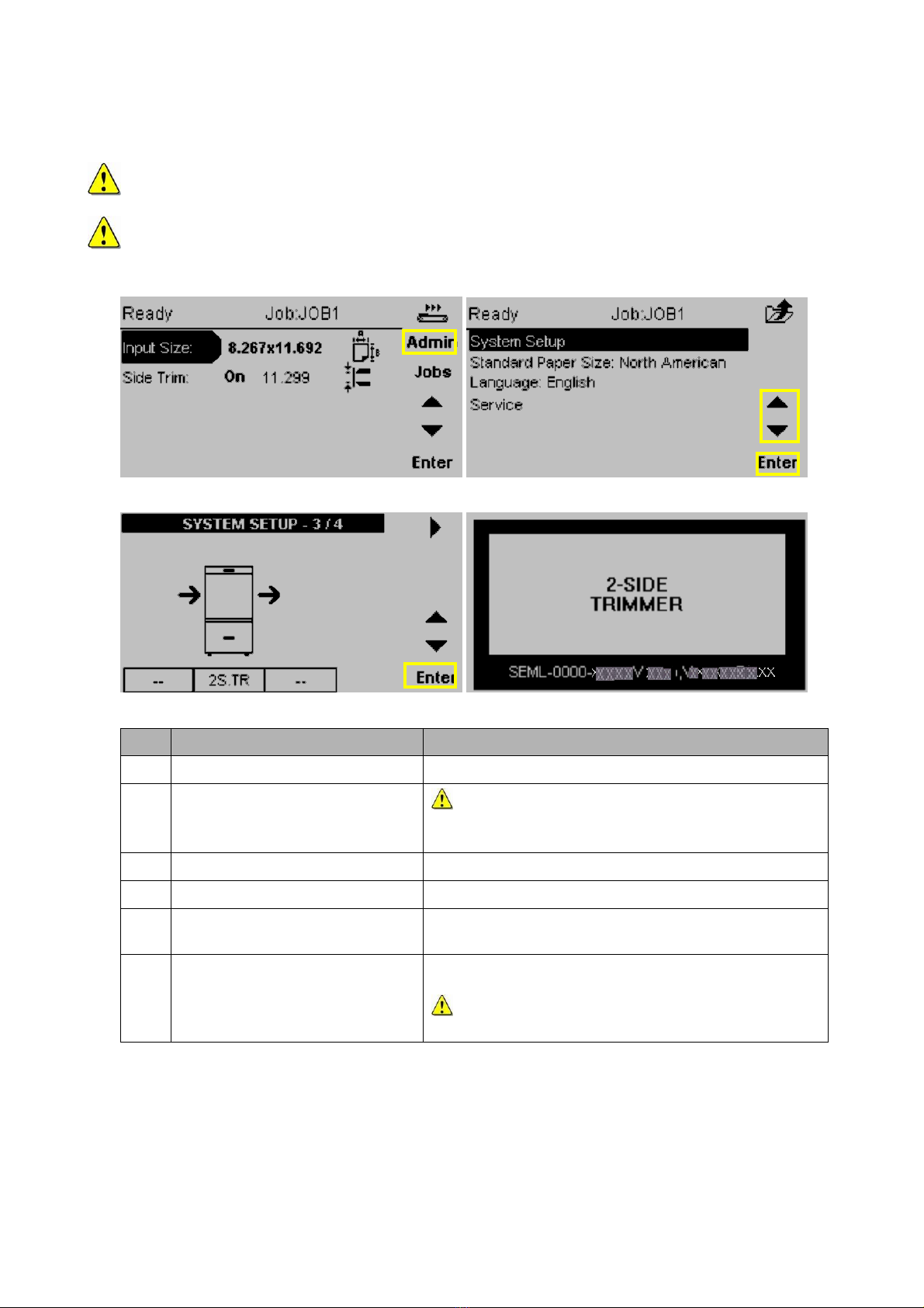
4.1 SYSTEM SETUP ......................................................................................................................................... 8
4.2 LANGUAGE ................................................................................................................................................ 9
4.3 JOB SETUP.............................................................................................................................................. 10
4.4 PAPER SIZE SETUP .................................................................................................................................. 11
4.5 JOB SETUP .............................................................................................................................................. 12
4.6 PAPER INPUT SIZE SETUP ........................................................................................................................ 13
4.7 SIDE TRIM ON /OFF ............................................................................................................................... 14
4.8 CENTRE OFFSET ..................................................................................................................................... 15
4.9 PURGE BUTTON ....................................................................................................................................... 16
5. TROUBLESHOOTING............................................................................................................................. 17
5.1 TRIM WASTE BIN FULL ............................................................................................................................. 17
5.2 CLEARING A PAPER JAM .......................................................................................................................... 18
5.2.1 Warnings / Cautions ..................................................................................................................... 18
5.2.2 Clearing jams inside ..................................................................................................................... 18
5. TROUBLESHOOTING (CONTINUED)....................................................................................................... 20
5.3 STOP IF BOOKLET IS TOO THICK................................................................................................................. 20
6. CLEANING / MAINTENANCE................................................................................................................. 21
6.1 GENERAL ................................................................................................................................................ 21
6.2 CLEANING THE BELTS............................................................................................................................... 21
6.3 REMOVING TRIM WASTE FROM WASTE AREA .............................................................................................. 22
7. TECHNICAL INFORMATION .................................................................................................................. 23

1. Safety
- The Bleed Trimmer may only be plugged into an approved and by circuit breakers protected
electrical installation, secured with a maximum of 16A.
- The outlet socket shall be installed near the equipment and shall be easily accessible.
- Never put your hands, other body parts or anything else than booklets within specifications in
the infeed or outfeed area of the Bleed Trimmer.
- Before cleaning, maintenance or repairs; always be sure to switch off the power switch and
to disconnect the power cord.
- Always follow all warnings marked on or supplied with the equipment.
- The equipment should only be placed on a solid surface with adequate strength to hold the
weight of the machine besides the usual maximum load.
- Always exercise care while moving or relocating the equipment.
- Keep magnets and all devices with a strong magnetic field away from the machine.
- Never attempt to perform maintenance or repairs other than described in this manual.
- Never remove covers or guards that are fastened with screws.
- Never install the equipment near a radiator or any other heat source.
- Never override or bypass electrical or mechanical interlock devices.
- In case of unusual sounds or noises, abnormal surface temperature or odors; disconnect the
power immediately and consult a qualified technician.
The manufacturer cannot be held responsible for arbitrary changes in the machine and the
originated damage.
Make sure that the Bleed Trimmer is NOT powered during installation or service activities.
This is a Class A product. In a domestic environment this machine may cause radio
interference. In which case the user may be required to take adequate measures.
Note: A domestic environment is an environment in which radio and television receivers can
be expected inside a range of 10 meters of the concerning machines.
RoHS
compliant
The Bleed Trimmer is RoHS compliant.
Only use RoHS compliant replacement parts.
4

2. General
Bleed Trimmer BT 30 is used together with Booklet Maker system Pro 30.
The main purpose of the Bleed Trimmer, further referred to as STR, is that it can be used for trimming the
bleed off the booklet. Booklets with a maximum up to 25 sheets 80g/m2can be trimmed from 2mm to 35mm
on each short edge of the booklet, to a minimum of 200 mm and a maximum of 320mm finished size.
Thereby it is also possible to trim asymmetrically. All actions concerning operating the STR and adjusting the
trim settings can be done by using the User Interface (UI) on the STR.
The example below shows what is possible with the Bleed Trimmer by using a different Center Offset
(symmetrical or asymmetrical):
5
Centre Offset:
15mm
Centre Offset:
-
15mm
Centre Offset:
0
mm
33,5mm Waste
33,5mm Waste
3,5mm Waste 18,5mm Waste
3,5mm Waste
18,5mm Waste
Input Size: Finished Size:
297.0
mm
260.0
mm

3. Basic information STR
See the picture below to get familiar with the components of the Bleed Trimmer.
All directions are seen from the paper flow direction.
6
Front Rea
r
Left
Ri
g
ht
To
p
1
3
4
Bottom 5
2
BT 30
No. Description
1 Top Cover
2 Trim Waste Bin
3 Power switch (inside)
4 User Interface (UI)
5 Belt Stacker
Due to mirrored versions of this product, typical Front and Rear designations that normally are viewed from
the operator location have been replaced by Left and Right. Left and Right are defined from the paper input
direction.
Clarification:
Right = Front for BT 30
Left = Rear for BT 30

3. Basic Information (continued)
See the Top View picture below to get familiar with the components inside the machine.
B
A
D
E
F
Outfeed
side
Infeed
side
1
2
C
7
8
3 6 4
5
No. Description No. Description
1 Docking Bracket A Motor 1, Knife
2 Transport Belts B Motor 7, Side Jogger
3 Knives C Motor 2, Knife
4 Solenoid
5 Trimmer Stop D Motor 3, Knife
6 Side Joggers E Motor 8, Side Jogger
7 Power Switch F Motor 4, Knife
8 Interlock Switch
7

4. Operating the STR
This section explains how to use the STR during normal operation.
From either side (top or bottom) 40mm of the finished booklet should be free from staples to ensure
safe operation.
NOTE: The System Setup has to be set once.
4.1System Setup
Fig. 1 Fig. 2
8
Fig. 3 Fig. 4
Step Action Remarks
1. Open the Top cover of the STR.
2. Turn on the STR with the Power
Switch Attention: Check if the Trim Waste Bin Drawer is
closed, otherwise the STR indicates ‘Cover
Open’.
3. Close the Top cover of the STR.
4. Enter ‘Admin’ menu Press the ‘Admin’ button (Fig. 1)
5. Enter ‘System Setup’ menu Use the ‘▲/ ▼buttons’ to select ‘System Setup’ and
press the ‘Enter’ button. (Fig. 2)
6. Select System Setup Set System Setup to STR (3 / 4) (Fig. 3)
Save and confirm with [Enter]
Attention: After saving the STR will restart
(Fig. 4).

4. Operating the STR (continued)
4.2Language
NOTE: The Language has to be set once.
Fig. 1 Fig. 2
9
Fig. 3
Step Action Remarks
1. Enter ‘Admin’ menu Press the ‘Admin’ button (Fig. 1)
2. Enter ‘Language:’ menu Use the ‘▲/ ▼buttons’ to select ‘Language:’ and press
the ‘Enter’ button. (Fig. 2)
3. Select Language Use the ‘▲/ ▼buttons’ to select the correct Language
(Fig. 3).
Save and confirm with [Enter]

4. Operating the STR (continued)
4.3Job Setup
Perform the following steps to set up the job:
1) Determine the width of the booklet before trimming (Input Size).
2) Determine the width of the booklet after trimming (Trim Size).
Trim waste
Trim waste
50-245 mm
Input size 204-340 mm
Trim size 200-320 mm
2-35 mm
2-35 mm
Min. staple distance 40 mm
If needed, adjust the trim asymmetrically (See Chapter 4.8 Centre Offset).
10

4. Operating the STR (continued)
4.4 Paper Size Setup
NOTE: “Standard paper size” has to be set once.
11
NOTE: “Select Paper Size” suitable to your requirements.
Fig.1 Fig.2
Fig.3
Step Action Remarks
1. Enter ‘Admin’ menu Press the ‘Admin’ button (Fig. 1)
2. Enter ‘Standard Paper Size:’
menu
Use the ‘▲/ ▼buttons’ to select ‘‘Standard Paper Size:’
and press the ‘Enter’ button. (Fig. 2)
3. Select ‘Standard Paper Size:’ Use the ‘▲/ ▼buttons’ to select the correct ‘Standard
Paper Size:’ (Fig. 3).
Save and confirm with [Enter]

4. Operating the STR (continued)
4.5 Job Setup
Fig. 1 Fig. 2
12
Fig. 3 Fig. 4
Step Action Remarks
1. Job Setup Press the ‘Jobs’ button two times (Fig. 1& 2).
2A. Make a new Job Press the ‘New’ button (Fig. 3).
2A. Enter Job name Use the ‘+/ -‘ and ‘►’ buttons (Fig. 4) to Enter the Job
name and press the ‘Enter’ button.
Attention: A “Loading Job” signal appears for a
few seconds.
2B. Adjust a Job Use the ‘▲/ ▼’ buttons to select a Job and press the
‘Enter’ button to load or confirm.
Attention: A “Loading Job” signal appears for a
few seconds.
3. Adjust Input Size and/or Side
Trim
Use the ‘▲/ ▼’ and the ‘+/ -‘ buttons to set the
desired settings for Input Size and Side Trim
(See Chapter:
4.6 Paper Input Size Setup
4.7 Side Trim ON/OFF )
4. Save Job After adjusting press ‘Jobs’ (Fig. 1) and save the current
Job or ‘Rename’ the adjusted Job by pressing the
‘Enter’ button (Fig. 2).
Attention: A “Saving Job” signal appears for a
few seconds.
Attention: After Rename a Job, repeat step 2A
‘Enter Job name’.

4. Operating the STR (continued)
4.6 Paper Input Size Setup
In this menu the Input Size can set or adjusted.
Fig. 1 Fig. 2
Fig.3
Step Action Remarks
1. Input Size adjustment Use the ‘▲/ ▼buttons’ to select ‘Input Size’ and press
the ‘Enter’ button (Fig. 1).
Use the ‘+/ -‘ buttons (Fig. 2) to switch between ‘A4’
and ‘A5’ paper Input Size .
2A. Adjust ‘Input Size’ A4 / A5
2B. Adjust ‘Input Size’ Length(A) /
Width (B)
Use the ‘▲/ ▼’ buttons (Fig. 3) to adjust the ‘Length
(A)’ or ‘Width (B)’ in mm and use the ‘+/ -‘ buttons to
adjust the values (A) or (B).
3. Save Input Size adjustments Save and confirm with [Enter] (Fig. 3).
13

4. Operating the STR (continued)
4.7 Side Trim ON / OFF
Fig. 1 Fig. 2
Fig. 3 Fig. 4
Fig. 5
Step Action Remarks
1. Side Trim ON/OFF Use the ‘▲/ ▼’ buttons on the UI to select ‘Side Trim’
and press the ‘Enter’ button (Fig. 1).
Use the ‘+/ -‘ buttons to select ON / OFF
2. Adjust ‘Side Trim’
3. Adjust ‘Finished Size’ Use the ‘▲/ ▼’ buttons (Fig. 3) to select ‘Finished Size’
and use the ‘+/ -‘ buttons to adjust the ‘Finished Size’.
Press ‘Enter’ (Fig. 3) to confirm the settings.
4. Save settings. After all desired settings are adjusted press ‘Jobs’
(Fig. 4) and press ‘Enter’ (Fig. 5) to save the settings.
Attention: A “Saving Job” signal appears for a
few seconds.
14

4. Operating the STR (continued)
4.8Centre Offset
For trimming the bleed off the booklet a Center Offset can be set. This means that it is possible to trim
asymmetrical (trim more from the upper or lower side of the booklet).
A positive Center Offset will result in a booklet trimmed more on the upper side of the booklet.
A negative Center Offset will result in a booklet trimmed more on the lower side of the booklet.
(See example below: Input Size 297.0mm, Finished Size 260.0mm)
Centre Offset:
1
5
mm
Centre Offset:
-1
5
mm
Centre Offset:
0mm
33,5mm waste
33,5mm waste
3,5mm waste 18,5mm waste
3,5mm waste
Finished Size:
260.0
mm
Input Size:
2
9
7.
0
mm
18,5mm waste
Fig. 1 Fig. 2
Step Action Remarks
1. Center Offset (if necessary) Use the ‘▲/ ▼’ buttons to select ‘Side Trim’ and press
the ‘Enter’ button (Fig. 1).
2. Adjust ‘Center Offset’ Use the ‘▲/ ▼’ buttons (Fig. 2) to select ‘Center Offset’
and use the ‘+/ -‘ buttons to adjust the ‘Center Offset’.
Press ‘Enter’ (Fig. 3) to confirm the settings.
3. Save settings. After the Center Offset is adjusted press ‘Jobs’ (Fig. 1)
and press ‘Enter’ (Fig. 2) to save the settings.
15

4. Operating the STR (continued)
4.9 Purge Button
Fig.1
Step Action Remarks
1. Press Purge Button. Use the ‘Purge buttons’ to move booklets forward on
Belt Stacker (Fig.1).
16

5. Troubleshooting
There are several errors or fault codes that generally can be solved by the operator:
When the Trim Waste Bin is full or trim
waste is prevented from falling down
into the Waste Bin, the message
‘Empty Trim Bin' will be displayed (Fig.
1).
When a Paper Jam appears, like Clear
Area, the message ‘Error STR…’ will
be displayed.
Fig. 1
5.1Trim Waste Bin Full
A
Fig.2 Fig.3
Step Action Remarks
1. Open the Trim Drawer. (Fig. 2)
2. Empty Trim Waste bin(s) (A). (Fig. 3; some versions have two waste bins)
3. Remove the remaining trim
Waste. Attention: It is possible that there is still some
trim waste left inside the STR.
4. Place the Trim Waste bin(s) back
in the Drawer.
(Fig. 3)
5. Close the Trim Waste Drawer. (Fig. 2)
17

5. Troubleshooting (continued)
5.2Clearing a Paper Jam
5.2.1 Warnings / Cautions
An increasing number of Paper Jams is an indication of the need to clean the belts.
The STR Upper knife blades are protected by a Knife Safety Plate that moves away during the
Trim cycle movement.
WARNING! Never put fingers or other body parts between knives.
5.2.2 Clearing jams inside
A
Fig.1 Fig. 2
Step Action Remarks
1.
1.1.
1.2.
Open the Top Cover.
Close the Top Cover.
The STR is trying to empty the
machine.
The STR will automatically try to empty the machine
when a Paper Jam is detected.
When the jam is not solved, the Knife blocks will
automatically move out of each other to make
space.
2. Pay attention to the indicated
area
Pay attention to the indicated area displayed on the UI
3. O
p
en the To
p
Cover.
4. Turn ‘OFF’ the STR.
5. Clear the indicated area : Take
the booklet out of the machine
The indicated area is displayed on the UI.
If necessary push down the Paper Stop (A).
6. Turn ‘ON’ the STR. A signal ‘Cover Open’ will appear.
7. Close the Top Cover. The Knife blocks will automatically move to each
other to set ready for current Job.
18

5. Troubleshooting (continued)
5.2 Clearing a Paper Jam (continued)
B
A
Fig.1 Fig.2
Step Action Remarks
1.
1.1.
1.2.
Open the Top Cover.
Close the Top Cover.
The STR is trying to empty the
machine.
The STR will automatically try to empty the machine
when a Paper Jam is detected.
When the jam is not solved, the Knife blocks
automatically move out of each other to make
space.
2. Pay attention to the indicated
area Pay attention to the indicated area displayed in the
UI.
3. O
p
en the To
p
Cover.
4. Turn ‘OFF’ the STR.
5. Clear the indicated area: Take the
booklet out of the machine
Pull the belts (A) in the STR towards the input area.
The booklet will move into the STR.
Pull the belts (B) in the STR towards the output area.
The booklet will move into the STR.
6. Take the booklet out of the
machine.
Push or pull the booklet inside the STR so it is possible
to take the booklet out of a machine.
7. Turn ‘ON’ the STR. A signal ‘Cover Open’ will appear.
8. Close the Top Cover of the STR. The Knife blocks of the STR will automatically
move to each other to set ready for current Job.
19

5. Troubleshooting (continued)
5.3 Stop if booklet is too thick
NVM ‘Stop if booklet too thick’ is a value to set a warning for the Operator when a booklet is too thick to trim.
There are 3 different warnings adjustable, which are:
Value 1 Value 2 Value 3
Booklet too thick! Not trimmed Booklet too thick (STR003) Booklet too thick (STR108)
(NO STOP: only message in (SOFT STOP: booklet (HARD STOP: booklet still
UI display) transported outside the machine) inside the machine)
Fig. 1 Fig. 2 Fig. 3
20
NOTE: Ask your service technician to install one of the values, which is suitable to your
requirements.
NOTE: Next step is only for Value 2 and 3. For Value 1 just push ”Escape” (Fig.1).
Step Action
Remarks
1.
1.1.
1.2.
Open the Top Cover.
Close the Top Cover.
The STR is trying to empty the
machine.
The STR will automatically try to empty the machine
when a Paper Jam is detected.
When the jam is not solved, the Knife blocks will
automatically move out of each other to make
space.
2. Pay attention to the indicated
area Pay attention to the indicated area displayed in the
UI.
3. O
p
en the To
p
Cover.
4. Turn ‘OFF’ the STR.
5. Clear the indicated area: Take the
booklet out of the machine
Pull the belts (A) in the STR towards the input area.
The booklet will move into the STR.
Pull the belts (B) in the STR towards the output area.
The booklet will move into the STR.
6. Take the booklet out of the
machine.
Push or pull the booklet inside the STR so it is possible
to take the booklet out of a machine.
7. Turn ‘ON’ the STR. A signal ‘Cover Open’ will appear.
8. Close the Top Cover of the STR. The Knife blocks of the STR will automatically
move to each other to set ready for current Job.
Table of contents
Other Plockmatic Trimmer manuals