Plot MAM-880 User manual

SCREWAIRCOMPRESSOR
TYPE: MAM-880(B)
USER
MANUAL
Shenzhen Plot electronic Co., Ltd
Address:Sixth floor, twenty fifth building, TIAN JIAN industrial estate,
SHANG BAO road; FU TIAN district; SHEN ZHEN
Telephone:(0755)83172098 83172068 Postal code:518034
Fax:(0755)83172966 E-mail:[email protected]
Web site:www.pltsz.com

NOTICE
Please read instruction manual before usage
Installation of MAM—8** can be performed only by professional technicians
Assembling position shall be considered carefully during mechanical installation in order to ensure
good heat dissipation and reduce electromagnetism interferences
Wiring shall be performed respectively according to regulations for heavy and weak current to reduce
electromagnetism interferences
Surge absorber must be communicated with inductive load such as AC contactor of output control of
relay
Output wiring shall be inspected carefully before switch up
Earthing terminal of this body part shall be earthed correctly (the third type of earthing) to increase
product’s capacity of resisting signal noise.
Motor’s rated current (current for stopping instrument automatically) shall be set according to rated
current indicated on motor’s name plate ×overload current multiplication factor of
motor/ 1.2
Features:
● LCD Chinese / English display
● With control functions of starting, stopping and operation for motor.
● With protection functions of preventing reverse rotation of air compressor.
● Temperature measurement and control
● Automatic adjusting of rate of load and controlling of pressure balance
● Selections of remote and local control
● Selections of interlocking and independent
● Function of RS485 communication

1、Basic Operation....................................................................................................................................................4
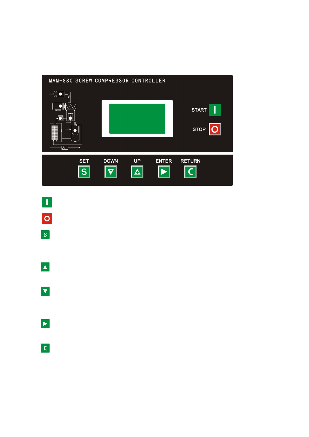
1、Button Explanation.......................................................................................................................................4
2、Indicator instructions....................................................................................................................................4
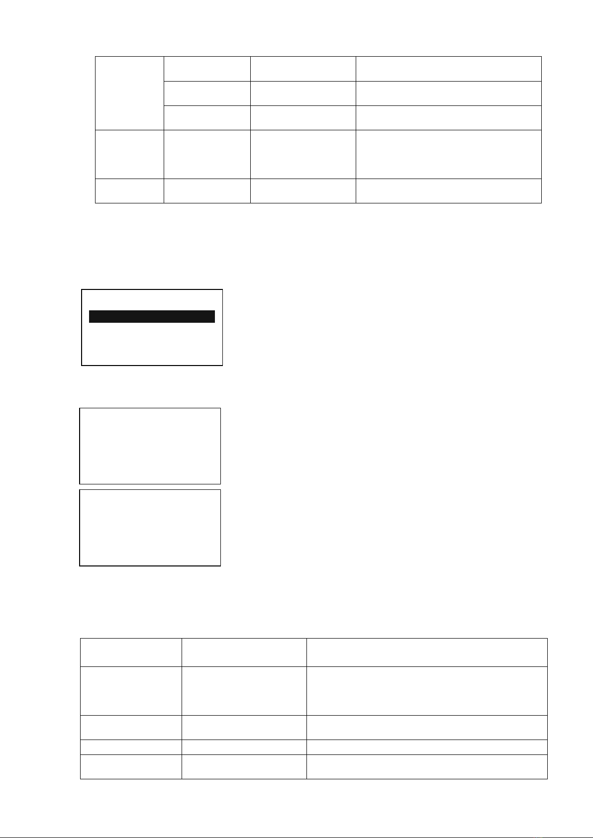
3、Display of status and operations...................................................................................................................5
4、Operating parameters....................................................................................................................................5
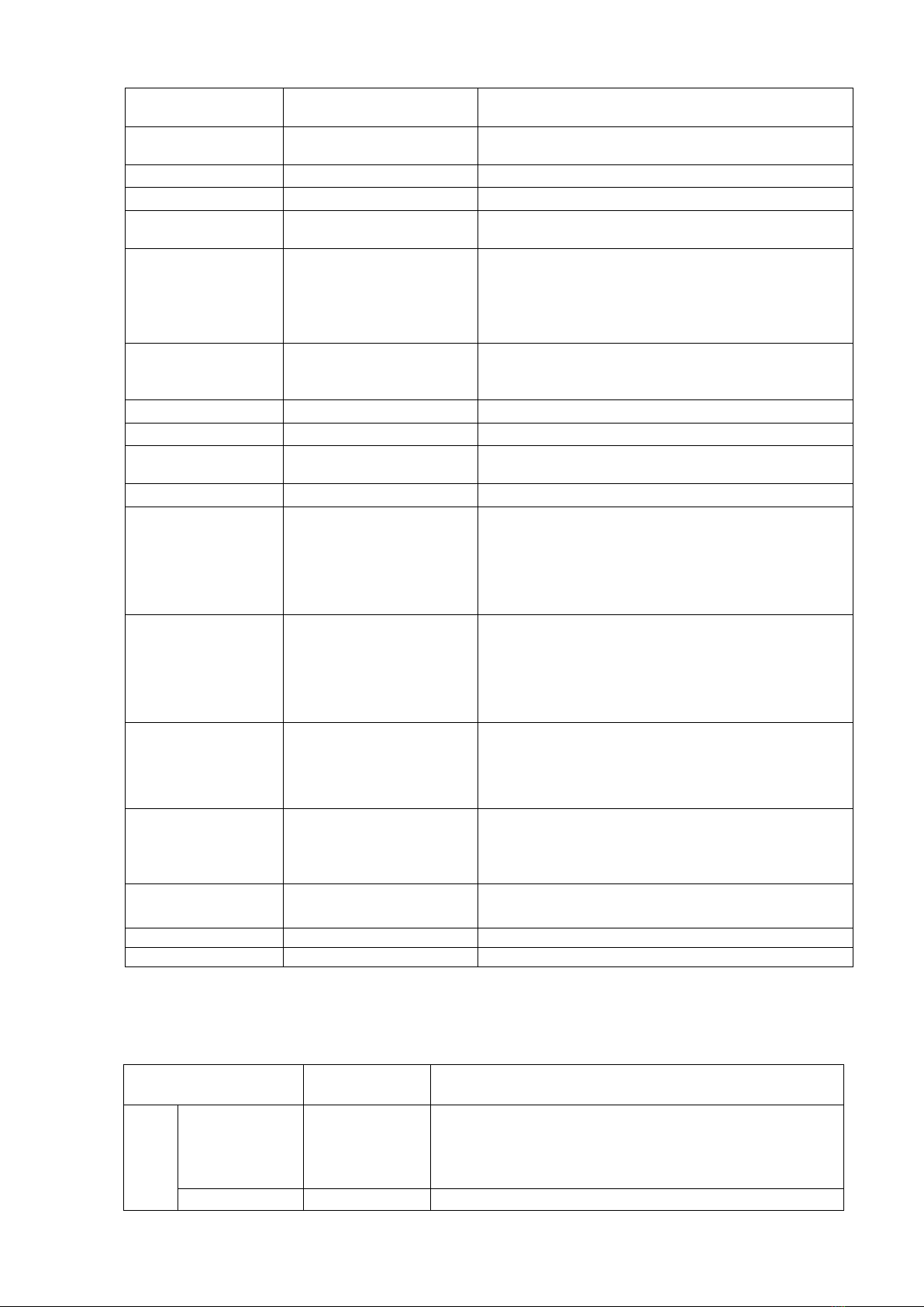
5、User Parameter (Customer Parameter):........................................................................................................6
6、Customer Parameter and Functions..............................................................................................................7
7、Factory Parameters.......................................................................................................................................9
8、Manufacturers and function..........................................................................................................................9
9、Calibration parameters................................................................................................................................10
10、the operating authority and password.......................................................................................................12
2、Technical parameters and functions .................................................................................................................12
3、Type and specification......................................................................................................................................13
1、Instruction of type ....................................................................................................................................13
2、Specification table for power of suited motor ............................................................................................13
4、Installation..........................................................................................................................................................14
1、Installation of transducer..........................................................................................................................14
2、Controller Installation.................................................................................................................................15
3、Terminal arrangement diagram...................................................................................................................15
5、Control principles.............................................................................................................................................16
1、LocalAutomatic control.............................................................................................................................16
2、. Remote automatic control.........................................................................................................................17
3、Local manual control................................................................................................................................17
4、Remote Manual Control.............................................................................................................................17
5、Network control........................................................................................................................................17
6、Temperature control of fan .......................................................................................................................18
7、Failure shutdown and emergency shutdown.............................................................................................18
6、Early-warning and prompts..............................................................................................................................18
1、Indication of early warning of oil filter ....................................................................................................18
2、Indication of early warning for air filter...................................................................................................18
3、Indication of early warning for oil separator............................................................................................18
4、Indication of early warning for lubricating oil ......................................................................18
5、Indication of early warning for grease ........................................................................................18
6、 Indication of early warning for belt ..........................................................................................18
7、High air temperature warning ............................................................................................................18
7、Controller protection ........................................................................................................................................19
1、Motor protection.......................................................................................................................................19
2、Gas Exhaust Over-temperature Protection ...............................................................................................19
3、Non-reversing Protection of Air Compressor...........................................................................................19
4、Overpressure Protection of Pressure Supply............................................................................................19
5、Malfunction Protection of Sensor.............................................................................................................19
8、Removal of Common Failures..........................................................................................................................19
1、Failures Review.........................................................................................................................................19
2、Common Failures and Causes..................................................................................................................20
9、Electrical diagram...............................................................................................................................................20

1、Basic Operation
1、Button Explanation
Figure 1.1.1
——Start Button: Press this button to start the compressor。
——Stop button:Press this button to stop the compressor。
——Set Button/ Loading / unloading Button: After modification, press this to confirm and
save modified data;When the compressor is running ,press this button to load or unload
under a certain pressure.
——Move up button/increase button: Data at current position is increased by pressing this
button when data are modified; Menu is moved upwards when menu is selected.
——Move down button / Descending button: Data at current position is descended by
pressing this button when data are modified; menu is moved downwards when menu is
selected.
——Shift button /Enter button: This button services as shift button when data are modified
and services as enter button when menu is selected.
——Back button / Reset button: This button services as back button when operate menu to come back
Parent menu; resetting is carried out by pressing this button for a little long time when failure
shutdowns
2、Indicator instructions

3、Display of status and operations
The display screen will be as follow when the units are powered on:
After power on, screen show this page
After 5 seconds, the main page will show up as:
Main page
Press “Move down button” to enter into Menu Selection Interface:
Level 1 menu screen
4、Operating parameters
Press “Move down button” or “Move up button” to move the black cursor to “RUN
PARAMETER”, press enter button to pop up submenu:
WELCOME USING
SCREW COMPRESSOR
AIR T:20℃
AIR P:0.60MPA
NORMAL STOP
C001 REMOTE
RUN PARA.
USER PARA.
FACTORY PARA.
CALBR PARA.
MOTER FAN CUR
TOTAL RUN TIME
THIS RUN TIME
MAINTAIN PARA.
HISTORY FAULT
SERIAL NUMBER
THIS FAULT
COM STATUS
Air filter indicator, when the air
filter warning light.
High temperature, the indicator light; Temperature
sensor fault the indicator light;
Oil filter indicator, when the air
filter warning light.
Oil separator warning, the indicator light。

Move the scroll bar to the corresponding menu item, press the enter key, see
the specific parameters, Such as view, "MOTER FAN CUR " move the scroll bar to
the " MOTER FAN CUR " menu item, press the enter key, switch to the motor and
fan current interface
If the menu popped up is at the last level, the black cursor will disappear. Press the
return button to return to the upper menu or the main page.。If the operation stops at a
certain page, it will automatically return to the main page after 60 Seconds
5、User Parameter (Customer Parameter):
In primary menu,, press the move button to move the black slider to the "USER
PARA." menu, press the shift button to switch to the following menu:
Move the cursor to the "P、T SET " menu, then press enter button to switch to
the following interface:
Move the cursor to the “LOAD P” menu, Press enter button ,Switch to the following
interface requirements to enter a user password
After showing this interface,The first bit data or password started flashing,
press “increase button” or “descending button” to modify the flashing data equal
MAIN(A)FAN (A)
A 50.1 2.1
B 50.1 2.1
C 50.1 2.1
P、T SET
TIME SET
OPERATION MODE
SEQ PARA. SET
LOAD P:
00.62 MPa
UNLOAD P:00.78MPa
FAN START:0080℃
FAN STOP:0075℃
INPUT CODE
**
**
CLR LIFE TIME
MAX LIFE TIME
LAN. SEL:EN
NEW USER PIN:****

to the first bit of password,Press the shift button, move the cursor to the next
data bit,modify the current data is equal to the second password data,
Accordance with the above , modify the third and fourth Finally, press the “Set
button” to confirm the input, the system verify the password is correct, switch to the
following interface:
The upper right corner with "* "prompt
said the system has passed the password
authentication
In as shown above interface, press “enter button” , then the data of loading pressure start to flash, users
can press “increase button” or “Descending button” to modify the present data. When finished, press
“Set Button” to confirm and save. the controller prompt sends out the short voice to tip.
6、Customer Parameter and Functions
First
Submenu Second submenu Preset Value Functions
SET P. T.
LOAD P. *.**MPa LOADING PRESSURE VALUE
UNLOAD P. *.**Mpa UNLOADING PRESSURE VALUE
FAN START ***℃
Control the fan starting. This value will
be set as “120℃” if there is no fan
present or the fan is not required to be
protected.”
FAN STOP ***℃Control the stopping of the fan
TIME SET
HOST START 0008S
When using the controller to protect the
motor, it is required that the time set here
will not meet the impulse starting current
of the motor, the value here must be
longer than the STAR DELAY TIME
plus LOAD DELAY TIME
FAN START 0006S
When using the controller to protect the
motor, it is required that the time set here
will not meet the impulse starting current
of the motor.
STAR DELAY 0006S Star pressure descending start delay time.
LOAD DELAY 0002S The loading delay time after star pressure
descending.
EMPTY DELAY 0020M Load free continuous running time, the
machine will automatically stop after this
time
STOP DELAY 0010S The machine will not stop until the load
free running status lasting till this time
START DELAY
0100S Machine can not be restarted before this
set time after stopped or over time
operation at load free state
OPERATION
MODE ON/OFF MODE NEAR/FAR
When the remote mode is set, both the
button on the controller and the remote
control button can turn on and off the
machines;When the near mode is set,only
the button on the controller can turn on
and off the machines.
LOAD P:
00.62 MPa *
UNLOAD P:00.78MPa
FAN START:0080℃
FAN STOP:0075℃

LOAD MODE AUTO/MANU When the manual mode is set, the
Load/Unload function can only be
executed by pressing “load/unload’button
COM MODE BAN/COMP./BLOCK
When this is set as “BAN” the
communication function is not available
When this is set as “COMP. ”
the
Controller as a slave, in accordance with
MODBUS protocol communications
with external devices
When this is set block,block control
active
COM ADD 0255 Communication address
BLOCKING
MODE
SEQ STATE SLAVE
Service as main or assistant air
compressor during interlocking
operation. The MAIN controls the
SLAVE
TURN TIME 9999 Hours
During interlocking operation, if one air
compressor continuously operates for
time period more than time set here and
rest time of one air compressor in
interlocking network has reached the
time set here, alternative rest is achieved
by starting the resting air compressor and
stopping the operating air compressor
SEQ NUMER 0016 Number of air compressors in
interlocking network during interlocking
operation
SEQ LOAD *.**MPa
The main air compressor searches for one
device in the interlocking network for
loading or starting when main air
compressor’s gas supply pressure is less
than the value set here during
interlocking operation
SEQ U.L. *.**MPa
The main air compressor searches for one
device in the interlocking network for
unloading or stopping when main air
compressor’s gas supply pressure is more
than the value set here during
interlocking operation
SEQ DELAY 0030S The least waiting time that the main air
compressor needs to continuously sends
control commands two time
CLR LIFE
TIME
OIL FILTER 0000H Reset time for the duration of oil filter
changing
O/A FILTER 0000H Reset time for O/G Separator changing
AIR FILTER 0000H Reset time for gas filter changing
LUBE 0000H Reset time for Lubricate Oil Changing
GREASE 0000H Reset time for Lubricate Grease
Changing
BELT 0000H Reset time for Belt Grease Changing
MAX LIFE
TIME
OIL FILTER 9999H Set this value to “0” will make the oil
filter alarm not available
O/A
SEPARATOR 9999H Set this value to “0” to disable the O/G
separator alarm function
AIR FILTER 9999H Set this value to “0” to disable the alarm
function of gas filter

LUB 9999H Set this value to “0” to disable the time
alarm of lub. oil
GREASE 9999H Set this value to “0” to disable the time
alarm of Lub. Grease
BELT 9999H Set this value to “0” to disable the time
alarm of belt.
LANG.SEL EN/CH EN
Set this value to “EN” , Display text in
English
Set this value to “CH” , Display text in
Chinese
NEW USER
PIN **** **** Customer could modify the user
password
7、Factory Parameters
The factory parameters can be looked over and modified with manufacturer password, but its operation
method is the same as that of user parameters. Please refer to following table for main functions and
purposes.
Manufacturers enter the correct password,press set button, switch to the factory
parameters of the interface as follows
………
Factory parameters "run time", "phase sequence protection," "Frequency
Selection" and the time need check super password to changes.
8、Manufacturers and function
PARAMETER Initial Value Functions
MOTOR CUR MAXIMUM
OVERLOAD VAULE OF
THE MOTOR /1.2
After the starting delay time, when the motor current
is greater than 1.2 times of the set value and less than
4 times of the set value, the unit will jump as per
overload feature.
FAN CUR Maximum allowable
motor overload value/1.2 Same as above
ALARM T. 105℃Pre-alarm when the temperature reaches this set value
STOP T. 110℃Alarm when the air exhausting temperature reaches
this set value.
INPUT CODE
**
**
MOTOR CUR:100.0A
FAN CUR:010.0A
ALARM T:0105℃
STOP T:0110℃
STOP P:00.90MPa
MAX U.L.:00.85MPa
RUN TIME:001234H
LOAD TIME:001001H

STOP P. 1.00MPa Alarm and stop the machine when the air supply
temperature reaches this set value
MAX U.L. 0.80MPa The Unload Limit Pressure in the Customer Parameter
must be set lower than this value.
RUN TIME ****Hours The manufacturer can modify the total running time
LOAD TIME ****Hours The manufacturer can modify the load running time
CLR FAULT **** Input the history failure password to clear all the
history failures.
CUR UN.BAL. 0006
When (the max. phase current / min. phase current) is
not greater than (1+set value), the unbalance
protection will stop the machine. If the set value is
greater than 15, the unbalance protection will be
unavailable.
LACK PAHSE 005.0 If set time of phase failure ≥20 seconds, phase failure
doesn’t function; If unbalance protection is activated,
it will stop operation.
DATA ****-**-** The manufacturer input the product date of the unit.
SERIAL ******** The manufacturer input the product No. of the unit
PHASE PRO. ON/OFF ON:Select sequence protection
OFF:Not select sequence protection
POWER FREQ 50H Set the power frequency
HIGH VOL. ****V
Controller detects the voltage higher than
the set value, the shutdown protection,
reported voltage is too high. Set this value
to 0000, the high voltage function is no
function
LOW VOL. ****V
Controller detects the voltage lower than
the set value, the shutdown protection,
reported voltage is too low. Set this value
to 0000, the low voltage function is no
function
LOW T PRO- -48℃
Controller detects the temperature is lower
than this value, display temperature is
too low, not allowed to start the air
compressor
TIME LIM 0000H
When the compressor run time is greater than TIME
LIM set, the controller will stop the compressor and
alarm ;
If the value set as ‘0000’the function is disable.
ALM STOP 0010H Warning time over here to set, compressor
report "warning too long" and stop
COM SET PARA ON/OFF
PARA1 ****
9、Calibration parameters
Calibration parameter used to set the controller data,Does not allow unauthorized users to view and
modify
PARAMETER Initial Value Functions
M
O
T
O
R
TARGET CUR 0000
Enter the current value, the controller will detect
user input value divided by the current to the
current value, calculate the current coefficient
COEF 1.000 Calibration current, the input coefficients.

A Controller displays the current value = sample
value × COEF
CUR ***.*A
Displays the current controller sampling current
values. This value is the real value can not be
set.
M
O
T
O
R
B
TARGET CUR 0000
Enter the current value, the controller will detect
user input value divided by the current to the
current value, calculate the current coefficient
COEF 1.000 Calibration current, the input coefficients.
Controller displays the current value = sample
value × COEF
CUR ***.*A
Displays the current controller sampling current
values. This value is the real value can not be
set.
M
O
T
O
R
C
TARGET CUR 0000
Enter the current value, the controller will detect
user input value divided by the current to the
current value, calculate the current coefficient
COEF 1.000 Calibration current, the input coefficients.
Controller displays the current value = sample
value × COEF
CUR ***.*A
Displays the current controller sampling current
values. This value is the real value can not be
set.
F
A
N
A
TARGET CUR 0000
Enter the current value, the controller will detect
user input value divided by the current to the
current value, calculate the current coefficient
COEF 1.000 Calibration current, the input coefficients.
Controller displays the current value = sample
value × COEF
CUR ***.*A
Displays the current controller sampling current
values. This value is the real value can not be
set.
F
A
N
B
TARGET CUR 0000
Enter the current value, the controller will detect
user input value divided by the current to the
current value, calculate the current coefficient
COEF 1.000 Calibration current, the input coefficients.
Controller displays the current value = sample
value × COEF
CUR ***.*A
Displays the current controller sampling current
values. This value is the real value can not be
set.
F
A
N TARGET CUR 0000 Enter the current value, the controller will detect
user input value divided by the current to the
current value, calculate the current coefficient

C
COEF 1.000 Calibration current, the input coefficients.
Controller displays the current value = sample
value × COEF
CUR ***.*A
Displays the current controller sampling current
values. This value is the real value can not be
set.
10、the operating authority and password
Controller provides multiple passwords and access management, according to
different levels of passwords, providing different levels of operating authority,
different levels of passwords and permissions as follows:
1. user's password: fixed as :___________
Permissions: allows to modify the load pressure unload pressure, fan start temperature, fan stop
temperature, start and stop mode, loading method, communication mode, communication address
and linkage parameters.
2. User Password: set as:___________
3. Permissions:Allows to modify all user parameters.
4. manufacturers sales password: this password can be modify, set to :___________
Permissions: Allows users to modify all the parameters, the user password, and the
parameters of some manufacturers, manufacturers selling password.
5. manufacturers Password: factory fixed:___________
Permissions: Allows users to modify all the parameters, the user password, and the parameters of
some manufacturers, manufacturers selling password.
6. Calibration Password: set as:___________
Permissions: allows you to modify the current parameters of the calibration parameters
7. Super Password: set as:___________
Permissions: Allows users to modify "run time " "phase sequence protection "
"power frequency " "max run time"
2、Technical parameters and functions
1、Digital input: Digital input of 3# circuit; digital output of relay of 5# circuit;
2、Simulation quantity: Pt100 temperature input of 1# circuit; 4~20mA input of transducer of 1# circuit; two
groups of three phase current input(CT provided);
3、Input voltage of phase sequence: three phase 380V/220V;
4、Controller’s power supply: AC20V、50Hz、10VA;
5、Measurement range displayed:
①、Oil temperature:-50~150℃; precision: ±1℃.
②、Air temperature:-50~150℃;precision:±1℃.
③、Operation time: 0~999999 hours.
④、Measurement range displayed for current:0~999.9A.
⑤、Pressure: 0~1.60MPa. Precision: 0.01Mpa.
6、Phase-sequence protection: When protector inspects wrong phase, response time≤2s (optional);
7、 Protection of motor: this controller has five basic protection functions for main motor and fan’s motor

①、block protection:When working current reaches to from 4 times to 8 times of set current after finish
starting, response time ≤0.2s;
②、Short circuit protection: when testing current reaches above 8 times of set current, response time≤0.2s;
③、Protection of phase failure: in case of phase failure of any one phase, operation time equals setup time;
④、Unbalance protection: when currents of any two phase differ 60~75%,operation time equals set time;
⑤、Protection characteristics of reverse time limit of overload (time unit: second),please see following
table(table 2.1.1),multiple=Iactual/Iset
motor operates with delay time according to overload factors and operation time shown in following table
(table 2.1.1) when motor’s working current is larger or equal to from 1.2 times and 3.0 times of set
current.
Iactual/Iset
Time parameters ≥1.2 ≥1.3 ≥1.5 ≥1.6 ≥2.0 ≥3.0
Operation time(S)
60 48 24 8 5 1
Table 2.1.1 curve table of reverse time limit for protection of motor
8、Temperature protection: when actual temperature measured is larger than temperature set; response time≤
2s;
9、Contact capacity of output relay: 250V,5A;Contact endurance 500000 times
10、Error of displayed current is less than 1.0%.;
11、RS485 communication
3、Type and specification
1、 Instruction of type
2、Specification table for power of suited motor
MAM 880(B)(T)(V)(40)
Maximum working current matching
with host motor
With voltage detection
With RS485 communication
B: pressure sensor; K: Pressure switch
880 controller
Serial

Parameter
Specification
Current range
(A)
Suited main
motor power
(KW) Remark Description
MAM880(20)8~20 4~10 Fan has three
levels of current,
such as 0.2-2.5A,
1-5A and 4-10A,
determined
according to
fan’s current
MAM880(40)16~40 8~20
MAM880(100)30~100 15~50
MAM880(200)80~200 40~100
MAM880(400)160~400 80~200
MAM880(600/5)100~600 50~300
4、Installation
1、 Installation of transducer
The transducer shall be installed at place where motor’s line current (rated current) can be measured,
thus controller can be set according to instructions on motor’s name plate, the detailed dimensions as
followed:
Figure 4.1.1. Structural dimensions of CT1 (ф36 through hole) Figure 4.1.2. Install dimensions of CT1
AB
B
A

Figure 4.1.3. Structural dimensions of CT2 (ф10 through hole) Figure 4.1.4. Install dimensions of CT2
2、Controller Installation
The controller is installed as plate. Room should be left around controller for wiring. The specific
dimensions are as follows:
Figure 4.1.5 Controller structure dimensions
139
239
Figure 4.1.6 Hole size
3、Terminal arrangement diagram

△
1211
CT1
C
B
A
c
b
10 9 8 765432
19
20
21
CT2
a
31302928
27
2625
24
23
22
FG
1
A
B
RS-485
C1
、
ub ua
uc 13 14 15 16 17 18
Figure 4.2.1 Terminal arrangement diagram
Terminal blocks of controller:
1 is common terminal COM1;2 is input terminal for emergent stop signal;3 is remotely controlled for
on/off signal input terminal;4 terminal is used to detect oil filter blocked;6 is RS485 A; 7 is RS485 B;8 is the
simulated ground (Earth);17 and 18 are the AC20V power source;22、23 terminals are Pressure Sensor signal
input;24、25、26 terminals are motor mutual inductor CT1 input;27、28、2 terminals are Fan mutual inductor
CT2 input;30、31 terminals are Temperature Sensor signal input;19、20、21 terminals Used to detect the phase
sequence and voltage;13 terminals is common terminal of output relay;14 terminals controls fan;15 terminals
controls load valve;16 terminals controls angle-shaped contactor;17 terminals controls star-shaped contactor;
18 terminals controls main contactor。
NOTE: Eelectromagnetism coil shall be connected with surge absorber during wiring, and
dotted lines are extendable functions.
5、Control principles
1、Local Automatic control
①. press down start button for starting: (Y-△start)
There is fives of self-test after controller is energized and it can not be started by pressing start
button .The air compressor starts by pressing start button after self-test finished. The course of
compressor’s start as followed: KM3 and KM2 are energized → Y-type status of start → delay time is
reached (Y-△change-over time); KM3 is de-energized (KM1 and KM3 are interlocked) and KM1 is
energized → motor operates with △type to finish start. During the course of starting, all
electromagnetism valves are de-energized to achieve no load start.
②. Automatic operation control:
When the motor is started to running in △status and load the magnetic valve with

power applied after a certain period of delay. air compressor is loaded and pressure inside gas
tank begins to increase. When increased air pressure is more than higher pressures limit (value of
unload pressure), electromagnetism valve for loading is de-energized and electromagnetism valve for
discharging is energized, meanwhile, the air compressor operates without load. If air pressure decreases
to set lower pressure limits (value of load pressure), the electromagnetism valve for loading is energized
again and electromagnetism valve for discharging is de-energized. Air compressor operates normally to
increase pressure in air tank. If the unload run time exceeds the set delay time of non-load, the
compressor will automatically stop motor’s operation to achieve automatic shutdown after works
without load for long time. Only when pressure decreases to lower pressure limits, the motor start
operation according to course of starting, then circularly repeat this step.
③. Manual loading/unloading under automatic status
When compressor in automatically runs state and runs at unload operation, press down load or
unloading button , the electromagnetism valve for loading joggles a little and comes back to unloading
status; if the pressure is less than relief pressure, the electromagnetism valve for loading is energized
and it returns to unloading status until gas supply pressure becomes larger than relief pressure and
device is at loading status. Unloading is performed when press down unloading button “S”. If the
pressure is higher than loading pressure, the electromagnetism valve for loading is de-energized and
turns to status of loading until gas supply pressure is less than loading pressure. If pressure is less than
loading pressure, the unloading button do not function.
④. Normal shutdown:
Press the button , the load magnetic valve will loss power and the unload magnetic will be applied
with power, after a while of delay (stop delay), the motor contactor will loss power, the host and fan will
stop running, after the restarting delay completed, the unload magnetic will loss power. Only pressing
the button could restart the motor.
⑤. Control of preventing frequent starting
Press stop button to stop operation; Air compressor can not be started up immediately after shutdown
due to operation without load for long time or failure shutdowns, and it can be started up again when
remaining delay time is zero which the time display window of the controller in a variety of shutdown
state shows.
2、. Remote automatic control
Remote automatic control and local automatic control are basically same, but the difference is that
starting up or stopping of devices can be achieved by means of control of remote switch.
3、 Local manual control
Control of starting and stopping are same as automatic control, but device is in status of unloading
operation after finish starting up and loading is carried out by pressing down loading and unloading button
to load. When gas supply pressure is more than relief pressure, the device unloads automatically. If doesn’t
press loading, unloading button, the device will operate with unloading until stops without load. During
unloading, press loading and unloading button to load. During loading, press loading and unloading button
to unload.
4、Remote Manual Control
The remote automatic control is almost the same as the local manual control, the only
difference is that the start and stop of the unit is controlled by remote control.
5、 Network control

①: When communication method is set “computer”, network control between computer and controllers can
be achieved
②: When communication method is set “interlocking”, network control between controllers can be achieved,
but the main air compressor only can service as 1# compressor.
6、 Temperature control of fan
When exhausting temperature is higher than fan’s starting temperature, fan operates; when exhausting
temperature is lower than fan’s stopping temperature, fan stops operation.
7、 Failure shutdown and emergency shutdown
When electrical failure or high exhausting temperature appears during process of operation, the
controller stops motor’s operation immediately. Air compressor only can be started up after failure is
eliminated. In case of emergency, press down emergency stop button to cut off power of controller and
contactors
6、Early-warning and prompts
1、 Indication of early warning of oil filter
①. Early warning for blockage of oil filter
The controller can display the message on the text display to remind the operator that
“ the air filter is blocked” by checking the pressure difference switch operating state.
②. Set the running time alarm of the air filter
The Text displays “OIL FILTER LIFE END” when the using time of the oil filter terminates.
2、 Indication of early warning for air filter
The Text displays “AIR FILTER LIFE END” when the using time of the oil filter terminates.
3、 Indication of early warning for oil separator
The Text displays “O/A LIFE END” when the using time of the oil separator terminates.
4、Indication of early warning for lubricating oil
The Text displays “LUBE LIFE END” when the using time of the lube terminates.
5、Indication of early warning for grease
The Text displays “GREASE LIFE END” when the using time of the grease terminates.
6、 Indication of early warning for belt
The Text displays “BELT LIFE END” when the using time of the belt terminates.
7、High air temperature warning
Controller detects the air temperature high, the text display “HIGH TEMPERATURE”

7、Controller protection
1、 Motor protection
MAM-880 air compressor controller provides all-round protection functions of short-circuit, locking,
phase failure, overload, imbalance for motor.
Electronic
failure Failure Display Reason
Short
circuit Display failure “HOST/FAN SHORT” Short circuit or rated current is set by mistake
Blocked Display failure “HOST/FAN BLOCK” Too large load, bearing wear and other
mechanical failure
Overload Display failure “HOST/FAN OVER
CARRY” Too large load, bearing wear and other
mechanical failure
Phase
failure Display failure “HOST/FAN LACK
PHASE” Power supply, contactor and phase failure of
motor
Unbalance Display failure “HOST/FAN UNBLANCE”
Poor contact of contactor, inside open-loop of
motor
2、 Gas Exhaust Over-temperature Protection
When the Air exhaust temperature is higher than the upper limit of set temperature, the controller would be
stopped ,The display will show “HIGHT T”.
3、 Non-reversing Protection of Air Compressor
When three-phase supply phase sequence connected to the air compressor is not the same with that set for
the controller, the on-site failure is displayed as “PHASE REVERSAL”, as a result, the controller cannot
start up the motor. Then just change any arbitrary two-phase power lines leading to check the rotation of
motor.
4、Overpressure Protection of Pressure Supply
When the gas exhaust pressure is higher than the upper limit of set pressure, the controller would be stopped
for warning, the on-site failure is displayed as “HIGH P”.
5、Malfunction Protection of Sensor
When pressure sensor or temperature sensor is disconnected, the controller would be stopped for warning.
the on-site failure is displayed as “**SENSOR FAULT”.
8、Removal of Common Failures
1、Failures Review
Shutdown caused by the external parts of controllers may be removed by inquiring the on-site failure or
historic failure, with the details shown as below:
Press Down button or Up button , to move the black scroll bar to “RUN PARAMETER” menu, then
press Enter button , the lower menu would be propped out:

Press Down key always and the following menu will appear:
Press Enter key and the following failure causes will appear:
In this case, just check if the temperature sensor is disconnected and if the sensor is damaged, etc.
2、 Common Failures and Causes
Failure Reason Disposal method
Air Exhaust
Temperature too
high Bad vent condition, Oil lacking etc. Check the vent condition and lubricant
amount etc.
Temperature
Sensor Failure Cable off or PT1OO damaged Checking the wiring and PT100
Over Pressure The pressure too high or the pressure
sensor failure Check the pressure and the pressure sensor
Pressure Sensor
Failure Cable off, Sensor damaged or the
cable connected reversed Check the wiring and sensor transformer
Lack Phase Power phase lacking or the Contactor
terminal damaged Check the power and contactors
Overloaded Voltage too low, tubes blocked,
Bearing Wear off or other mechanical
failure or wrong set data etc.
Check the set data, Voltage, bearings,
tubes and other mechanical system.
Unbalance Power unbalance, Contactor damaged
or the internal open of the motor Check the power, contactors and the motor
Rotor Lock Voltage too low, tubes blocked,
Bearing Wear off or other mechanical
failure or wrong set data etc.
Check the set data, Voltage, bearings,
tubes and other mechanical system.
Short Circuit Wrong Wiring, Incorrect Data setting
etc. Checking the wiring and set the data
correctly
Wrong Phase
Sequence Reversed Phase sequence or phase off
Check the wiring
Overload or
Rotor locking
during starting
Host start time set to a valueless than
the star angel time delay Reset the host starting time to be longer
than star angel delay + Load delay time
M
OTORS CURRENT
TOTAL RUN TIME
THIS RUN TIME
MAINTENANCE SET
HISTORY FAULT
PROD DATE NO.
THIS FAU
LT
STOP:T1 SENSOR FAULT
0170℃
This manual suits for next models
1
Table of contents
Popular Air Compressor manuals by other brands

Atlas Copco
Atlas Copco SF 15+ Instruction book

Sullair
Sullair LS-20T Operator's manual and parts list

Ingersoll-Rand
Ingersoll-Rand 7/26E Operation and maintenance manual

paasche
paasche D500 Instructions and parts list

Xiaomi
Xiaomi Mi Portable Electric Air Compressor manual

Sealey
Sealey MAC01 instructions