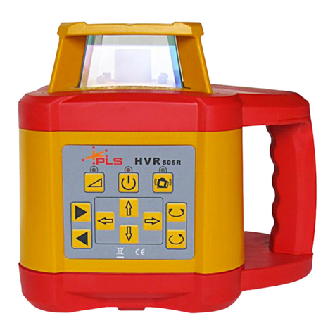
PLS HVR 505 User manual

PLS HVR 505
OPERATING
MANUAL
PACIFIC LASER
SYSTEMS
The Professional Standard

TABLE OF CONTENTS
Introduction.........................Page 1
Safety Information..............Page 2
Batteries.............................Page 3
Keypad...............................Page 4
Operation............................Page 5
Functions............................Page 6
Applications........................Page 7
Remote Control..................Page 8
Checking Calibration..........Page 9
Specifications.....................Page 10
Warranty.............................Page 11
PLS HVD Detector.............Page 12

INTRODUCTION
1
ROTATION HEAD UP BEAM
RE-CHARGING PLUG
KEYBOARD
DOWN BEAM
EXIT WINDOWS
HANDLE
The PLS HVR 505 is a fully automatic,
self-leveling laser used for height transfer
and layout. The HVR 505 R is a traditional,
visible red beam rotary laser used for both
interior and exterior layout. The HVR 505 G
is a highly visible, green beam rotary laser
ideally used for interior layout. The HVR 505
G may also be used for exterior applications.
The rechargeable PLS HVR 505 contains
micro-controlled charging technology.
CAUTION: DO NOT ATTEMPT TO CHARGE
STANDARD ALKALINE BATTERIES OR
WARRANTY WILL BE VOIDED.
The PLS HVR 505 may be used in vertical
and horizontal mode and has an up and
down plumb beam. It also has an additional
line marker (scanning) function and may
be controlled by the PLS RC 505 remote
control.
The instrument is water resistant and may
be used in the rain, if necessary. Unit may
not be submerged in water.

SAFETY INSTRUCTIONS
Laser Safety
The PLS HVR 505 R is a class II laser
according to 21CFR1040. The PLS HVR
505 G is a Class IIIA laser. Follow the
instructions on the warning labels which are
shown in the following illustrations:
PLS HVR 505 R
Laser Power:
635 nm
<1mW
Laser Class ll
Do not remove the attached warning labels.
The manufacturer and its dealers are not
liable for any defects and the consequences
from this removal.
! Attention ! The internal laser sources
comply with with laser classes II and IIIA.
Do not disassemble the instrument. In
case of inappropriate repairs, laser radiation
may arise in excess amounts of the marked
labels and liability may be incurred if there
is damage.In cases of inappropriate
processing, malfunctions are possible
without external visible damage.
The unit charger should only be used
indoors.DO NOT ATTEMPT TO CHARGE
STANDARD ALKALINE BATTERIES.
Attention: This instrument contains
nickel cadmium batteries. Nickel cadmium
batteries must be recycled or disposed of
properly. WEEE-Reg.: DE23874031
2
CAUTION
LASER RADIATION
DO NOT STARE INTO BEAM OR VIEW
DIRECTLY WITH OPTICAL INSTRUMENTS
MAX OUTPUT POWER <1mW
WAVELENGTH 635-670nm
CLASS II LASER PRODUCT
DANGER
LASER RADIATION
DO NOT STARE INTO BEAM OR VIEW
DIRECTLY WITH OPTICAL INSTRUMENTS
MAX OUTPUT POWER <1mW
WAVELENGTH 635-670nm
CLASS III A LASER PRODUCT
PLS HVR 505 G
Laser Power:
532 nm
<5mW
Laser Class lllA

The PLS HVR 505 uses rechargeable
NiMH batteries.
For on-board chargeable battery, insert
the battery re-charger receptacle plug in
the charging panel outlet of the battery
cover back.
Insert converter’s AC receptacle plug in
an AC outlet and insert the converter’s
DC receptacle plug in the charging panel’s
DC outlet.
When the charging lamp is on, charging
is in process.
When the charging lamp is green, charging
is completed.
NOTE: The charging process takes
approximately 7 hours to complete for
rechargeable batteries.
AC/DC converter’s suitable power range:
50-60Hz; voltage 85V-265V.
DO NOT USE ALKALINE BATTERIES
WITH YOUR PLS HVR 505.
If it is necessary to replace the NiMH
batteries, the battery chamber may be
removed with a Philips screwdriver.
Purchase replacement NiMH batteries
from an authorized dealer.
Use PLS HVR 505 with caution in humid
or wet weather conditions.Do not put the
laser back into the case unless it is thor-
oughly dry. Condensation may corrode the
battery connections and/or cause distortion
of beams in lighthouse.
BATTERIES
3

KEYPAD
4
1) POWER
SWITCH
ON/OFF
2) POWER
LIGHT
4) MANUAL
INDICATOR
6) DIRECTION
SCANNING
KEY
9) CLOCKWISE
STEPPING
ROTATION
KEY
11) Y AXIS
SLOPE
ADJUSTING
KEY
12) AUTOMATIC
DRIFT SYSTEM
10) X AXIS
SLOPE
ADJUSTING
KEY
7) MANUAL
KEY
8) COUNTER
CLOCKWISE
STEPPING
ROTATION
KEY
3) LOW
POWER
(BLINK)
5) ROTATIONAL
SPEED
ADJUSTMENT

1) Power switch: turn on or off unit.
2) Power light: red light, power on.
3) Low Battery lndicator:LED blinks, the
battery should be charged or replaced.
4) Manual Indicator: green LED on in
manual mode.
5) Accelerate key: variable speed, 0-60-120-600
r.p.m., press multiple times to adjust through
a cycle.
6) Scanning key: variable angle, 0-10º-45º-90º-
180º, press multiple times to adjust through
a cycle.
7) Manual/automatic key: to change from
automatic to manual leveling.
8) Counterclockwise rotation key: when rotation
is stopped, press to start scanning of orientation.
9) Clockwise rotation key: when rotation is
stopped, press to start scanning of orientation.
10) Adjustment key in X slope direction: when the
instrument is in the manual mode, press to adjust
slope of X direction.
11) Adjustment key in Y slope direction: when the
instrument is in the manual mode, press to adjust
slope of Y direction.
12) Tilt or ADS (automatic drift system) blinks
slowly when active, blinks quickly to warn user of
a change in alignment from original set up.
KEYPAD OPERATION –
FUNCTIONS AND INDICATORS
5
N
G

FUNCTIONS
Press 1 (See keypad chart) The unit is self-level-
ing and power light is lit. Press the key again and the
unit will turn off.
After laser has automatically leveled, the laser beam
stops blinking. The laser will rotate up to 600 r.p.m. If the
gradient exceeds 5º, the manual indicator will blink.
NOTE: If the unit does not level within 5 minutes,
it will shut off.
Rotation Mode
The 5 key adjusts rotation speed. Adjust through
a cycle. To stop rotation, press the 5 key.
Rotation will be clockwise.
When the 9 key is pressed, rotation will be
counterclockwise.
Scanning Mode
Adjust rotation speed until the laser stops rotating.
Press the 6 key and the unit starts scanning
mode. Press the 6 key again to adjust
scanning angle.
Press 8 clockwise or 9 counterclockwise;
key will move scanning laser line.
Setting Slope
The PLS HVR 505 can set slope on dual axes.
Press the 7. The manual indicator is on.
Setting slope of X direction: Aim X1 of
the instrument in the direction necessary
to set slope.Press 10.
The laser beam moves upwards or downwards.
Setting slope of Y direction.
AimY1 of the instrument in the direction
necessary to set slope.
Press 11.
The laser beam moves upwards or downwards.
Automatic Drift System
Press 12. Press the TILT key, the power indicator blinks
slowly.After the instrument has leveled automatically
for about 3 seconds, the ADS function is activated.The
power indicator will blink quickley, and automatic leveling
function shuts off when the instrument is disturbed by
external circumstances.At the same time, the laser
module will stop scanning and start blinking.
6
X1
X2 Y1
Y2
Power switch

Turn the instru-
ment on. The
leveling LED
is flashing and
the instrument
is self leveling.
If the
LED lights
continuously the rotary head
starts and the laser beam will be turned on. Attach the PLS
HVD 505 Detector at this reference point on a rod and move
this height to zero.Now the respective difference in levels to
the reference height can be measured on the ground. It is
useful to use a flexible rod to measure positive and negative
values simply.
Laying out Slope Using the PLS HVR 505
Fasten the PLS HVR 505 to a tripod and plumb up over the
benchmark or hub.Make certain that the PLS HVR 505 is
positioned on the tripod so that the X axis points toward where
you need slope. Auto-level the PLS HVR 505 by depressing
the top green button. Once the laser is level
and rotating at 600 rpm, attach the detector to the grade rod.
Take the grade rod with the detector attached to the end of the
needed distance (end of pipe, footing or form board). Find
level on the detector by a solid tone or by the solid line on the
LCD.Next, depress the top center button on the remote (RC
505) to engage the manual mode on the PLS HVR 505. Then
lower the detector by the correct distance
based on the needed slope.Some exam-
ples are listed below. Depressing the right
red button lowers the laser towards the
detector.Hold down the right-pointing
arrow key until the detector beeps that you
are within range.Now fine-tune the laser
adjustment by going up using the left-arrow
key or down using the right-arrow key until
the laser is locked on with a solid tone or
by the solid line on the LCD.
Examples
APPLICATIONS
7
Height
Transfer
(Leveling)
-1% Slope @100'
Lower the detector
on the grade rod
12" from level
-3% Slope @100'
Lower the detector
on the grade rod
36" from level
-1% Slope @50'
Lower the detector
on the grade rod 6"
from level
-3% Slope @50'
Lower the detector
on the grade rod
18" from level
-1% Slope @25'
Lower the detector
on the grade rod 3"
from level
-3% Slope @25'
Lower the detector
on the grade rod 9"
from level
For a positive slope layout, reverse the above examples.
..................................................
............
............

APPLICATIONS
The PLS HVR 505 should be checked, like all measuring instruments,
before use.Set the PLS HVR 505 on a stable surface - Method A.
Turn the laser on and let it level. Mount the PLS HVD 505 Detector at a
fixed distance, e.g. at 90 feet, and move it onto the laser plane.
Now turn the instrument around to each 90°point and let the instru-
ment level. In each case, measure the difference to the first height.
If the deviation is smaller than 1/8 inch, the instrument is within the
specification. In the case of larger deviations the instrument has to
be calibrated.
8
CHECKING CALIBRATION
REMOTE CONTROL
Caution !The automatic leveling is
switched off in manual mode.If the
instrument gets moved it will not turn
off.In the semi-manual mode the tilt
control is active only in X direction. We
recommend using a second detector
to control the sloped plane.
Vertical Use
The PLS HVR 505 has third
leveling axis (z-axis).Place the
instrument as shown. The plumb
beam will be leveled automatically.
The turning rotor head projects an
upright plane to the plumb beam at
an angle of 90°. To adjust the align-
ment line use the arrow keys to
move the laser beam right and left.
Right angles can then be measured simply and quickly.
..........................
The PLS HVR 505 may be used with the PLS RC 505 infrared
remote control. Point the remote in the direction of the PLS HVR
505 for remote operation. Remote distance is 70 feet indoors and
40 feet outdoors.There are 9 keys on the panel of the remote unit.
The remote panel matches the keypad of the PLS HVR 505.
Pressing any key will make the indicator lamp blink once indicating
remote signal is being sent.

A. Instrument Checking - Method B
(1) Place the instrument at the point of 90 feet in front of wall (or set a
scaleplate at the point of 90 feet away from the instrument), and then
adjust the level of the base approximately to aim the X1 to the wall (or
scaleplate) as depicted at right.
(2) After switching on the
power, use the detector
measuring the h1 of X1-
beam on the wall or scale-
plate.(3) Loosen the screw
of the tripod and then turn
the instrument 180Oto
measure the h2 of X2-beam
on the wall or scaleplate.
D-value between h1 and h2 ought to be less than 1/8 inch.
(4) Check the Y-beam in the same way.
B. Level Adjusting
If the D-value between h1 and h2 is more than 1/8 inch, adjust the
instruments according to the following steps:
1. Y-axis adjustment. (1) Press the Key ON/OFF when power indicator
lights & automatic leveling of the instrument starts up.(2) Press the key
“ ” and “Ý”simultaneously for 3 seconds; when mode indicator blinks,
the instrument enters mode of adjusting. (3) Press the key
“ ” or “ ” of Y-axis repeatedly and check the position of laser beam
when mode indicator is blinking until the D-value between h1 and h2 is
less than 1/8 inch. (4) Press the Key “ ” and “Ý”simultaneously to
hold the adjustment until mode indicator goes out. If the instrument is
set horizontally, Y-axis adjustment stands for Z-axis adjustment.
C. X-axis Adjustment
(1) Press the Key ON/OFF when power indicator lights & automatic lev-
eling of instrument starts up.(2) Press the Key “ ” and “ ” simultane-
ously for 3 seconds.When undervoltage indicator blinks, the instrument
enters mode of adjusting. (3) Press the Key “ ” or “Ý”of X-axis
repeatedly and check the position of laser beam while undervoltage
indicator is blinking till D-value between h1 and h2 is less than 1/8 inch.
(4) Press the Key “ ” and “ ” simultaneously to hold the adjustment
until undervoltage indicator goes out. If canceling the adjustment,
please shut off the instrument and then turn it on. If the adjusting range
exceeds range permitted, the power indicator will flash.
Notice: Once the D-value exceeds the error range that instrument
permits, please contract the supplier to repair the instrument.
D. Plumb Point Check
(1) Place the instrument between two walls with distance of 90 feet.
(2) Place the instrument on its side and then adjust. (3) Switch on the
power, and then measure the middle point of the laser beam on the
wall: hA, hB and hA’, hB’.
(4) 1=hA-hA’, 2=hB-hB’. D-value between 1 and 2 ought to be
less than 1/8 inch.
E. Adjusting If-D value between 1 and 2 is more than 1/8 inch,
adjust the instrument according to procedure described in B.
CHECKING CALIBRATION
9
Ý
Ý
Ý
Ý
Ý
Ý
Ý
Ý
Ý

ROTARY SPECIFICATIONS
10
PLS HVR 505:
Accuracy: +/- 1/8 inch @100 feet
3mm @ 30 meters
Down point accuracy: +/- 1/8 inch @10 feet
3mm @ 3 meters
Up point accuracy: +/- 1/8 inch @100 feet
3mm @ 30 meters
Leveling range: 5º
Operation range: Radius 500 feet w/detector
150m
Rotation speed: 0 - 600 rpm
Light source: laser diode,
wavelength 635nm, <1mW
(HVR 505 R)
wavelength532 nm, <5mW
(HVR 505 G)
Operating temperature: -4ºF (-20ºC) to
+122ºF (+50ºC)
Storage temperature: -22ºF (-30ºC) to
140ºF (60ºC)
Laser Class: II Caution (21CFR1040)
(HVR 505 R)
IIIA DANGER (HVR 505 G)
Power supply: 4 x D Size
NiMH Batteries
Operating time: approximately 20 hours
Charging time: maximum 7 hours
(NiMH ONLY)
Protection grade: IP64 (Water- resistant),
not submersable
Size / Weight:7 inch x 5 inch x 6 inch
135mm X135mm X 17mm
3.6 lbs (unit only)
3.0 kg
PLS RC 505 Remote Control:
Operating distance 70 feet
Charger LDG 2+2:
Input: 100-240V AC / 47-63Hz
Output: 12V / 1.25A
Use the charger indoors only! Do not attempt
to charge Alkaline Batteries.
Design and specifications are subject to
change without prior notice.

WARRANTY
11
In the event of a claim please contact your
PLS dealer or PLS.Attempts at repair or
detectable improper treatment will void any
warranty claim. Please use the original
transport case for shipment.
This product is warranted by PLS•Pacific
Laser Systems to the original purchaser to
be free from defects in material and work-
manship under normal use for a period of
one year from the date of purchase. During
the warranty period and upon proof of pur-
chase, the product will be repaired or
replaced (with the same or similar model at
our option) without charge for either parts or
labor through PLS.The purchaser shall
bear all shipping, packing and insurance
costs. Upon completion of the repair or
replacement, the unit will be returned to the
customer, freight prepaid. The warranty will
not apply to this product if it has been
abused or altered. Without limiting the fore-
going, battery leakage, dents or gouges to
the plastic housing, broken optic windows,
damage to the switch/LED membrane are
presumed to result from misuse or abuse.
Tampering with or removal of the caution or
certifications labels voids this warranty.
Neither this warranty nor any other warranty,
express or implied, including implied war-
ranties of merchantability, shall extend
beyond the warranty period. No responsibili-
ty is assumed for any incidental or conse-
quential damages.This warranty gives you
specific legal rights, and you may have other
rights which vary from state to state.

PLS HVD 505 DETECTOR
12
1. SPECIFICATIONS
Available Distance: From rotary PLS HVR 505 (2.0 in)
Accuracy: Precise detecting: +
_1mm ( +
_0.04in)
Rough detecting: +
_2mm ( +
_0.08in)
Detecting Indication: Bi-surface LCD, buzzer
Power:DC9V alkaline battery
Automatic Power-off Time: Approx. 20 minutes
Working Temperature: -4oF to +122oF (-20oCto +50oC)
Dimensions: 135 (L) X 65 (W) X 24.5 (H)mm
5-3/4" x 2-3/4" x 1"
Weight: 0.15kg (0.44lbs) (with battery)
2. LCD Rough Detecting
Reference Position
Display:
Precise Detecting
Reference Position
Display:
Higher than
reference
(high
frequency
beep)
In reference
line (long
beep)
Lower than
reference
(high
frequency
beep)
Poor Power: Buzzer On:
Buzzer Off:

OPERATING MANUAL
13
Buzzer ON/OFF
Once power on,
default of
buzzer is on)
Laser
Receptor
LCD (Both
on Front
Shell &
Back Shell)
Detecting
Mode
Power
Switch
Buzzer
Mark
36mm
5/12 Inches
3. PANEL
CAUTION:
The HVD 505 R + G detectors are
dedicated and unique to each HVR
505 R + G rotary laser and may not be
used with other laser tools.

PACIFIC LASER
SYSTEMS
The Professional Standard
PAC IFIC L ASER S Y S T E MS
2550 KERNERBLV D.
SAN RAFAEL, CA 94901
WWW.PLSLASER.COM
1800 6014500

PLS HVR 505
MANUAL
DE INSTRUCCIONES
PACIFIC LASER
SYSTEMS
El EstándarProfesional

ÍNDICE
Introducción Página 1
Información de seguridad Página 2
Pilas Página 3
Teclado Página 4
Funcionamiento Página 5
Funciones Página 6
Aplicaciones Página 7
Control remoto. Página 8
Verificación de la calibración Página 9
Especificaciones Página 10
Garantía Página 11
Detector PLS HVD Página 12

INTRODUCCIÓN
1
CABEZAL DE ROTACIÓN
HAZ ASCENDENTE
ENCHUFE
DE RECARGA
TECLADO
HAZ DESCENDENTE
VENTANAS DE SALIDA
MANGO
El sistema PLS HVR 505 es un láser de auto
nivelación totalmente automático que se utiliza
para transferencia de altura y replanteo.El HVR
505 R es un láser rotativo con haz rojo visible
tradicional que se utiliza para replanteos en interi-
or y exterior.El HVR 505 G es un láser rotativo
con haz verde altamente visible que se utiliza
principalmente para replanteos en interior.El
HVR 505 G también puede utilizarse para aplica-
ciones en exteriores.El PLS HVR 505 recargable
dispone de tecnología de carga microcontrolada.
PRECAUCIÓN: NO INTENTE CARGAR LAS
PILAS ALCALINAS ESTÁNDAR. HACERLO
ANULA LA GARANTÍA.
El PLS HVR 505 puede utilizarse en modo verti-
cal y horizontal y posee una plomada hacia arriba
y hacia abajo. También tiene una función adi-
cional de marcador de línea (rastreo) y puede
controlarse con el control remoto PLS RC 505.
El instrumento es resistente al agua y podría uti-
lizarse bajo la lluvia en caso necesario.La unidad
no debe sumergirse en agua.

INSTRUCCIONES DE SEGURIDAD
Seguridad del láser
El PLS HVR 505 R es un láser de clase II de
acuerdo con la norma 21CFR1040. El PLS HVR
505 G es un láser de clase IIIA. Siga las instruc-
ciones de las etiquetas de advertencia que se
muestran en las siguientes ilustraciones:
PLS HVR 505 R
Potencia del láser:
635 nm
<1 mW
Láser de clase II
No retire las etiquetas de advertencia. El fabri-
cante y sus distribuidores no se responsabilizan
de ningún defecto ni de las consecuencias de reti-
rar las etiquetas de advertencia.
Atención: Las fuentes internas del láser cumplen
con las reglamentaciones de láser de clase II y
IIIA. No desarme el instrumento.En caso de que
se realicen reparaciones inadecuadas, puede ocur-
rir una radiación láser que exceda los montos que
figuran en las etiquetas marcadas, lo que impli-
caría la responsabilidad por los daños ocurridos.El
inapropiado procesamiento puede originar un mal
funcionamiento sin daños externos visibles.
El cargador de la unidad debe utilizarse úni-
camente en interiores.
Atención: Este instrumento contiene pilas
de níquel-cadmio, las cuales deben reci-
clarse o desecharse de manera apropiada.
Reg. WEEE: DE23874031
2
PRECAUCIÓN:
RADIACIÓN LÁSER
NO MIRE FIJA O DIRECTAMENTE EL HAZ
CON INSTRUMENTOS ÓPTICOS.
MÁXIMA POTENCIA DE SALIDA <1 MW
LONGITUD DE ONDA 635-670 NM
PRODUCTO LÁSER DE CLASE II
PELIGRO
RADIACIÓN LÁSER
NO MIRE FIJA O DIRECTAMENTE EL HAZ
CON INSTRUMENTOS ÓPTICOS.
MÁXIMA POTENCIA DE SALIDA <1 MW
LONGITUD DE ONDA 635-670 NM
PRODUCTO LÁSER DE CLASE III A.
PLS HVR 505 G
Potencia del láser:
532 nm
<5 mW
Láser de clase IIIA
Other manuals for HVR 505
3
Table of contents
Languages:
Other PLS Measuring Instrument manuals