Plumbob 934172 User manual

Version date: 18.02.19 plumbob.eu
Standard Bathroom Extractor Fan 100mm (4")
FR Extracteur de salle de bain standard
DE Standard-Badezimmerabluftventilator
ES Extractor para baño
IT Aspiratore da bagno
NL Badkamer afzuigventilator
PL Wentylator łazienkowy
934172
934172_Manual.indd 1 18/02/2019 09:44

2
Fig.I
Backplate
Support arrière
Rückplatte
Placa posterior
Piastra posteriore
Rugplaat
Tylnia płytka
Front cover
Protection frontale
Vordere Abdeckhaube
Tapa frontal
Copertura frontale
Voorste afdekking
Przednia osłona
Ø 115mm
Screw
Vis
Schraube
Tornillo
Vite
Schroef
Wkręt
Fig.II
Fig.III
Glass
Verre / Vitre
Fensterglas
Cristal
Vetro
Glas
Szyba
Fan
Extracteur
Ventilator
Ventilador
Ventola
Ventilator
Wentylator
Fastening ring
Anneau de fixation
Befestigungsring
Anilla de retención
Ghiera di fissaggio
Bevestigingsring
Pierścień mocujący
Indoor
Intérieur
Innenbereich
Interior
Interno
Binnen
Wewnątrz
Outdoor
Extérieur
Außenbereich
Exterior
Esterno
Buiten
Na zewnątrz
Fastening ring
Anneau de fixation
Befestigungsring
Anilla de retención
Ghiera di fissaggio
Bevestigingsring
Pierścień mocujący
Installation hole
Trou d’installation
Installationsöffnung
Orificio de montaje
Foro di installazione
Installatieopening
Otwór instalacyjny
Glass
Verre / Vitre
Fensterglas
Cristal
Vetro
Glas
Szyba
Fan
Extracteur
Ventilator
Ventilador
Ventola
Ventilator
Wentylator
Ø 103mm Fig.IV
Fig.V Fig.VI
Brown
Marron
Braun
Marrón
Marrone
Bruin
Brązowy
Motor
Moteur
Motor
Motor
Motore
Motor
Silnik
L
N
LN
live
Sous-tension
Phaseleiter
fase
fase
live - onder spanning
Przewód pod napięci-
em
neutral
Neutre
Neutralleiter
neutro
neutro
neutraal
Przewód zerowy
Blue
Bleu
Blau
Azul
Blu
Blauw
Niebieski
Yellow / Green
Jaune / Vert
Gelb / Grün
Amarillo / Verde
Giallo / Verde
Geel / Groen
Żółty/Zielony
Thermal Link
Pont thermique
Thermische Verbindung
Fusible térmico
Collegamento termico
Thermische verbinding
Łącze termiczne
230V~50Hz
Zone 3
Zone 2
Zone 0
Zone 0
Zone 2
Zone 2
Zone 3 Zone 3
Zone 3
Zone 2
Zone 0
Zone 1
GB - Zone
FR - Zone
DE - Zone
ES - Zona
IT - Zona
NL - Zone
PL - Strefa
934172_Manual.indd 2 18/02/2019 09:44

plumbob.eu 3
English................04
Français ..............06
Deutsch ..............08
Español...............10
Italiano ...............12
Nederlands.........14
Polski ..................16
934172_Manual.indd 3 18/02/2019 09:44

4
GB
Description of Symbols
The rating plate on your tool may show symbols. These represent important
information about the product or instructions on its use.
Wear hearing protection.
Wear eye protection.
Wear breathing protection.
Wear head protection.
Wear hand protection.
Read instruction manual.
Caution!
For indoor use only
Risk of electrocution!
Correct erection angle is 1 out and 4 up
Class I construction (protective earth)
Conforms to relevant legislation and safety standards.
Environmental Protection
Waste electrical products should not be disposed
of with household waste. Please recycle where facilities exist.
Check with your local authority or retailer for recycling advice.
Specication
Extractor Fan Safety
WARNING: Always disconnect power at the service breaker before installing
or servicing
• This product is intended for installation by a qualied service person
• Means for disconnection must be incorporated in the xed wiring in accordance
with the current wiring regulations
• Do not make any live electrical connection to the extractor fan until
installation is complete
• If duct work is positioned higher than the extractor fan, a condensation trap must
be tted as close as possible to the fan to prevent water ingress
• This product is not intended for use in ambient temperatures exceeding 50°C
• Do not use this product to exhaust fumes or vapour produced from fuel burning
devices or non-electrical appliances
• Check building safety regulations before installing the extractor fan in a room
with a fuel burning device and ue to ensure it is safe to do so. If in doubt,
consult a qualied service person
• Do not locate any ON/OFF switches within distance of persons using
a shower or bath
• Ensure location of fan and structural changes in walls and windows comply with
any building regulations. If in doubt, consult a qualied professional
Intended Use
Single speed wall, window or panel mounted extractor fan suitable for bathrooms,
utility rooms and water closets. This extractor fan is intended for domestic use in
bathroom zone 3 only (Fig. I).
Unpacking Your Product
• Carefully unpack and inspect your product
• Familiarise yourself with all its features and functions
• Ensure all parts of the product are present and in good condition
• If any parts are missing or damaged, have such parts replaced before
attempting to use this product
Installation
• The extractor fan is suitable to be wall mounted (Fig. II) or window
mounted (Fig. III)
• Use suitably rated 2-core cable to connect the fan to the electrical supply
• Fits 100mm (4") duct (not supplied)
Introduction
Thank you for purchasing this Plumbob product. This manual contains information
necessary for safe and effective operation of this product. This product has unique
features and, even if you are familiar with similar products, it is necessary to read this
manual carefully to ensure you fully understand the instructions. Ensure all users of
the product read and fully understand this manual.
Original Instructions
Voltage: 230V~50Hz
Wattage: 12W
Extraction rate: 18.33l/s / 66m3/hr
IP rating: IPX0
Electrical class: I
Noise level at 1m: 45dB(A)
Prole depth: 83mm
Dimensions (L x W x H): 150 x 100 x 150mm
Weight: 0.45kg
As part of our ongoing product development, specications
of Plumbob products may alter without notice.
4x
1x
Technical Abbreviations Key
VVolts
~, a.c. Alternating current
, d.c. Direct current
W, kW Watt, kilowatt
dB(A) Decibel sound level (A weighted)
l/s Litres per second
m3/hr Cubic metres per hour
934172_Manual.indd 4 18/02/2019 09:44

5
Extractor fan location
• Install the extractor fan at the maximum height that the room size
or conditions permit
• Fit the fan securely using appropriate xtures to suit the material of
the wall or window
• Position the extractor fan the furthest distance from the main source of air
replacement (e.g. doorway) to maximise airow across the room
Wall hole preparation
WARNING: Ensure there are no pipes, cables or obstructions in the interior or
exterior of the intended installation wall area. If in doubt, consult a
qualied professional.
WARNING: Before drilling, check wall material is suitable for fan installation
and complies with regulations.
IMPORTANT: Fit duct at a downward angle away from the fan to
ensure condensation and water drains away from the fan.
Core drill hole creation
1. Mark the centre point of the installation hole position on the internal wall
2. Use the centre point to create the 115mm diameter circle suitable for the duct
3. Follow core drill bit manufacturer’s instructions to create the circular hole in the
internal wall, then repeat on the external wall
4. Cut duct to required length
5. Fit duct
6. Make necessary repairs to the wall to prevent gaps and secure duct in place
Note: Allow ller or mortar to set before continuing fan installation.
Drill bit & chisel hole creation
1. Mark the centre point of the installation hole position on the internal wall
2. Use the centre point to create the 115mm diameter circle suitable for the duct
3. Drill a single centre hole through the wall so that the hole is visible on the
external wall
4. Drill a series of shallow holes around the edge of the cutting line circle, ensuring
not to drill through the wall
5. Use a suitable bolster or uted plugging chisel to remove brick between drill
holes to create a hole in the internal wall
6. Use the single hole in the external wall as a guide to repeat the process
(see stages 3 – 5) to complete the hole
7. Cut duct to required length
8. Fit duct
9. Make necessary repairs to the wall to prevent gaps and secure duct in place
Note: Allow ller or mortar to set before continuing fan installation.
Isolating switch & cables
WARNING: Do not connect any electrical supply during or after this stage.
1. Isolate the mains supply
2. Ensure the extractor fan electrical rating matches the mains supply
3. Ensure no pipes or cables are near or behind the isolating switch location. If in
doubt, consult a qualied professional
4. Install the isolating switch and ON/OFF switch, and necessary cables
5. Make connections within isolating switch and ON/OFF switch
Wall tting the fan & backplate (Fig. II)
Positioning the backplate
1. Remove the front cover by removing the single screw at bottom
of the fan (Fig. IV)
2. Ensure the edge of the spigot is smooth and free from burrs
3. Position the backplate so the front cover holding screw is at the bottom
4. Insert into the installation hole
5. Ensure the backplate is at the appropriate horizontal angle
6. Mark the xing hole positions on the wall
7. Remove the backplate from the installation hole
8. Drill screw holes in the wall and use wall plugs or appropriate ttings for the
material, if required
Mounting the backplate
1. Feed cables through to the fan terminals
2. Insert the backplate and spigot into the installation hole, see‘positioning
the backplate’
WARNING: Do not overtighten duct onto the backplate spigot, it can restrict
fan movement.
3. Secure backplate into the wall using screws or appropriate fasteners, if required
Note: Do not overtighten screws.
Window tting the fan
& backplate (see Fig. III)
1. Cut a 103mm diameter hole
2. Remove the front cover by removing the single screw at the bottom
of the fan (Fig. IV)
3. Position the backplate so the front cover holding screw is at the bottom
4. Insert into the installation hole
5. Ensure the backplate is at the appropriate horizontal angle
6. Attach fastening ring, on the other side of the glass, to the backplate
spigot (Fig. V)
7. Feed cables through to the fan terminals
Electrical connection (see Fig. VI)
1. Ensure main electrical supply is isolated
2. Connect cables to the fan
3. Ret front cover by replacing screw (Fig. IV)
4. Connect the isolating switch to the electrical supply
5. Restore electrical supply to the extractor fan
Note: Fuses for the appliance must not exceed 5A in xed wiring circuits.
Operation
• Operate the extractor fan through an ON/OFF switch, such as a light switch or
independent switch
Maintenance
Cleaning
WARNING: Isolate the extractor fan from the main power supply before any
cleaning or maintenance. If in doubt, consult a qualied service professional.
• Remove front cover (Fig. IV) to clean
• Never use caustic agents to clean plastic parts. If dry cleaning is not sucient,
a mild detergent on a damp cloth is recommended
• Dry thoroughly before retting
Contact
For technical or repair service advice, please contact the helpline
on (+44) 1935 382 222
Web: https://www.plumbob.eu/en-GB/
Address:
Powerbox
Boundary Way
Lufton Trading Estate
Yeovil, Somerset
BA22 8HZ, United Kingdom
Disposal
Always adhere to national regulations when disposing of electrical products
that are no longer functional and are not viable for repair.
• Do not dispose of power tools, or other waster electrical and electronic
equipment (WEEE), with household waste
• Contact your local waste disposal authority for information on the correct way
to dispose of power tools or electrical and electronic equipment
plumbob.eu
934172_Manual.indd 5 18/02/2019 09:44

6
FR
Description des symboles
La plaque signalétique gurant sur votre outil peut présenter des symboles. Ces symboles
constituent des informations importantes relatives au produit ou des instructions concernant
son utilisation.
Port de protection auditive
Port de lunettes de sécurité
Port de masque respiratoire
Port de casque
Port de gants
Lire le manuel d’instructions
Attention !
Pour usage intérieur uniquement !
Risque d’électrocution !
Le bon positionnement de l'échelle devrait respecter une inclinaison d'angle
avec un ratio d'1 longueur (à l'horizontale) sur 4 (à la verticale).
Construction de classe I (Mise à la terre).
Conforme aux réglementations et aux normes de sécurité pertinentes.
Protection de l’environnement Les appareils électriques usagés ne doivent pas
être jetés avec les ordures ménagères. Veuillez les recycler dans les centres prévus
à cet effet. Pour plus d'informations, veuillez contacter votre municipalité ou point
de vente.
Introduction
Nous vous remercions d’avoir choisi cet équipement Plumbob. Ces instructions contiennent
les informations nécessaires au fonctionnement efcace et sûr de ce produit. Veuillez lire
attentivement ce manuel pour vous assurer de tirer pleinement avantage des caractéristiques
uniques de votre nouvel équipement. Gardez ce manuel à portée de main et assurez-vous que tous
les utilisateurs l’aient lu et bien compris avant toute utilisation.
Traduction des instructions originales
Consignes de sécurité relatives
aux extracteurs
AVERTISSEMENT : Toujours déconnecter l’alimentation au niveau du
disjoncteur principal avant toutes opérations d’installation ou d’entretien.
• Cet appareil doit impérativement être installé par un électricien qualié.
• Des moyens de déconnexion doivent être utilisés sur le câblage xe,
conformément aux règles relatives au câblage.
• Ne pas mettre l’extracteur sous tension an d’avoir compléter l’installation.
• Si le conduit d’air est positionné plus haut que l’extracteur, un piège à
condensation doit être installé au plus près possible de l’extracteur an de
prévenir la pénétration d’eau.
• Ce produit n’est pas prévu pour un usage sous températures ambiantes
au-delà de 50°C.
• Ne pas utiliser ce produit pour l’extraction de fumées, gaz ou vapeurs émanant de
dispositifs de combustion ou tout autres dispositifs non-électriques.
• Vériez les dispositions relatives à la construction et à la sécurité avant d’installer
cet extracteur dans une pièce équipée d’un dispositif de combustion, an de
vérier que cela peut être eectuer en toute sécurité. En cas de doute, veuillez
consulter un professionnel qualié.
• Ne pas positionner d’interrupteur marche/arrêt (ON/OFF) à portée de toute
personne utilisant une douche ou une baignoire.
• Assurez-vous quelemplacement de l’extracteur ainsi que les changements
apportés à la structure des murs et fenêtres sont conformes aux normes
de construction en vigueur. En cas de doute, veuillez consulter un
professionnel qualié.
Usage conforme
Extracteur de salle de bain à vitesse unique. Installation murale, sur fenêtre ou sur
panneau. Conçu pour les salles de bain, les buanderies et les toilettes. Cet extracteur
est conçu pour un usage domestique uniquement dans les « zones 3 » des salles de
bain (voir Fig. I).
Déballage
• Déballez le produit avec soin.
• Familiarisez-vous avec toutes les caractéristiques et fonctions du produit.
• Vériez que toutes les parties du produit sont présentes et en bon état.
• Si des pièces sont endommagées ou manquantes, faites-les réparer
ou remplacer avant d’utiliser l’appareil.
Installation
• L’extracteur est compatible avec une installation murale (voir Fig. II) ou une
installation sur fenêtre (voir Fig. III).
• Utilisez un câble à deux conducteurs adéquats pour connecter l’extracteur à
l’alimentation électrique.
• L’extracteur est compatible avec les conduits d’air de 100 mm (4") (non fourni).
4x
1x
Caractéristiques techniques
Tension : 230 V~, 50 Hz
Puissance nominale : 12 W
Capacité d’extraction : 18,33 l/s (66 m3/h)
Indice de protection : IPX0
Classe de protection électrique : I
Niveau sonore à 1 m : 45 dB(A)
Profondeur du prole : 83 mm
Dimensions (L x l x H) : 150 x 100 x 150 mm
Poids : 0,45 kg
Du fait de l’évolution constante de notre développement produit,
les caractéristiques des produits Plumbob peuvent changer
sans notication préalable.
Abréviations pour
les termes techniques
VVolt
~, a.c. Courant alternatif
, d.c. Courant continu
W, kW Watt, Kilowatt
dB(A) Puissance acoustique
en décibel (A pondéré)
l/s Litres par seconde
m3/hr Mètres cubiques par heure
934172_Manual.indd 6 18/02/2019 09:44

7
Positionnement de l’extracteur
• Installez l’extracteur à la hauteur maximale en fonction des conditions et de la
taille de la pièce.
• Installez l’extracteur en toute sécurité à l’aide de xations appropriées au
matériau du mur ou de la fenêtre.
• An d’améliorer la capacité d’extraction de l’extracteur, positionnez celui-ci le
plus loin possible de la source principale de remplacement d’air
(ex. porte principale).
Préparation de l’installation murale
AVERTISSEMENT : Vériez la présence de tuyaux, câbles et obstructions à
l’intérieur et sur l’extérieur du mur sur lequel l’installation doit être eectuée.
En cas de doute, veuillez consultez un professionnel qualié.
AVERTISSEMENT : Avant de commencer à percer, vériez que le matériau
du mur est adéquat à l’installation de l’extracteur et est conforme aux normes
en vigueur.
IMPORTANT : Positionnez le conduit d’air à un angle vers le bas à partir de
l’extracteur an que la condensation s’écoule et reste à l’écart de l’extracteur.
Préparation à l’aide d’une scie trépan
1. Marquez le point central du trou à eectuer sur le mur interne.
2. Utilisez le point central an de dessiner un cercle de 115 mm de diamètre
pour le conduit d’air.
3. Suivez les instructions du fabricant de la scie trépan an de percer à travers
le mur interne, puis répétez cette étape sur le mur externe.
4. Coupez le conduit d’air à la longueur requise.
5. Installez le conduit d’air.
6. Eectuez les réparations nécessaires sur le mur an de sécuriser le conduit d’air
en place. Remarque : Laissez sécher le mortier avant de continuer l’installation
de l’extracteur.
Perçage à l’aide d’un foret et d’un ciseau
7. Marquez le point central du trou à eectuer sur le mur interne.
8. Utilisez le point central an de dessiner un cercle de 115 mm de diamètre
pour le conduit d’air.
9. Percez un trou à travers le mur interne de manière à ce que celui-ci soit visible sur
le mur externe.
10.Percez une série de trous peu profonds sur le bord de la ligne de coupe, en vous
assurant de ne pas traverser le mur externe.
11.À l’aide d’un ciseau de maçon ou d’un ciseau à rainurer, retirez le matériau de la
zone de perçage an de créer un trou sur le mur interne.
12.Utilisez le trou sur le mur externe comme guide, puis répétez les étapes 3 à 5
ci-dessus an de créer un trou sur le mur externe.
13. Coupez le conduit d’air à la longueur requise.
14. Installez le conduit d’air.
15. Eectuez les réparations nécessaires sur le mur an de sécuriser le conduit
d’air en place.
Remarque : Laissez sécher le mortier avant de continuer l’installation
de l’extracteur.
Interrupteur d’isolement et câbles
AVERTISSEMENT : Ne pas connecter l’alimentation électrique pendant ou
après cette étape.
1. Isolez l’alimentation électrique.
2. Vériez que l’indice de protection électrique de l’extracteur corresponde à celui
de l’alimentation.
3. Vériez la présence de tuyaux ou câbles à proximité ou derrière l’emplacement
de l’interrupteur d’isolement. En cas de doute, veuillez consulter un
professionnel qualié.
4. Installez l’interrupteur d’isolement, l’interrupteur marche/arrêt (ON/OFF) et les
câbles nécessaires.
5. Eectuez les connexions nécessaires au niveau de l’interrupteur d’isolement et
l’interrupteur marche/arrêt (ON/OFF).
Installation murale de l’extracteur
et du support arrière (Fig. II)
Positionnement du support arrière
1. Retirez la protection frontale en retirant la vis unique présente en bas de
l’extracteur (Fig. IV).
2. Assurez que le bord à l’arrière de l’extracteur soit lisse et sans bavures.
3. Positionnez le support arrière de manière à ce que le trou de xation de la
protection frontale soit positionné en bas.
4. Insérez le support arrière dans le trou mural prévu à cet eet.
5. Vériez que le support arrière soit positionné correctement à l’horizontale.
6. Marquez la position des trous de xation sur le mur.
7. Retirez le support arrière hors du mur.
8. Percez les trous en fonction des marquages puis insérez des chevilles ou des
xations appropriées au matériau du mur.
Installation du support arrière
1. Passez les câbles à travers an de les positionner à proximité des bornes de
l’extracteur.
2. Insérez le support arrière dans le trou prévu à cet eet, voir « Positionnement du
support arrière ».
AVERTISSEMENT : Ne pas trop serrer le conduit d’air sur le support arrière, cela
pourrait limiter le mouvement de l’extracteur.
3. Sécurisez le positionnement du support arrière dans le mur à l’aide de vis ou de
xations appropriées.
Remarque : Ne pas trop serrez les vis.
Installation sur fenêtre de l’extracteur et du
support arrière (Fig. III)
1. Coupez un trou de 103 mm de diamètre.
2. Retirez la protection frontale en retirant la vis unique présente en bas de
l’extracteur (Fig. IV).
3. Positionnez le support arrière de manière à ce que le trou de xation de la
protection frontale soit positionné en bas.
4. Insérez le support arrière dans le trou prévu à cet eet.
5. Vériez que le support arrière soit positionné correctement à l’horizontale.
6. Attachez l’anneau de xation à l’arrière du support, de l’autre côté de
la fenêtre (voir Fig. V).
7. Passez les câbles à travers an de les positionner à proximité des bornes
de l’extracteur.
Connexion électrique (Fig. VI)
1. Vériez que l’alimentation électrique principale est isolée.
2. Connectez les câbles aux bornes de l’extracteur.
3. Replacez la protection frontale à l’aide de la vis (Fig. IV).
4. Connectez l’interrupteur d’isolement à l’alimentation électrique.
5. Restaurez l’alimentation électrique.
Remarque : Les fusibles utilisés avec l’appareil ne doivent pas excéder 5 A sur
les circuits à câblage xe.
Instructions d’utilisation
• Mettez l’extracteur en marche à l’aide de l’interrupteur marche/arrêt (relié à
l’interrupteur éclairage par exemple), ou à l’aide d’un interrupteur indépendant
Entretien
Nettoyage
AVERTISSEMENT : Isolez l’extracteur de la source d’alimentation principale
avant toutes opérations d’entretien ou de nettoyage. En cas de doute, veuillez
consulter un professionnel qualié.
• Retirez la protection frontale (voir Fig. IV) pour nettoyer l’appareil.
• N’utilisez jamais d’agent caustique pour nettoyer des pièces en plastique. Si le
nettoyage à sec n’est pas susant, nettoyez à l’aide d’un chion humide et d’un
détergent doux.
• Séchez complètement l’appareil avant de le réinstaller.
Contact
Pour tout conseil technique ou réparation, veuillez nous contacter :
- Téléphone : (+44) 1935 382 222
- Site web : https://www.plumbob.eu/fr-FR/
- Adresse : Powerbox
Boundary Way
Lufton Trading Estate
Yeovil, Somerset
BA22 8HZ, United Kingdom (Royaume-Uni)
Recyclage
Lorsque l’appareil n’est plus en état de fonctionner et qu’il n’est pas réparable,
recyclez celui-ci conformément aux réglementations nationales.
• Ne jetez pas les outils électriques, batteries et autres déchets d’équipements
électriques ou électroniques (DEEE) avec les ordures ménagères.
• Contactez les autorités locales compétentes en matière de gestion des déchets
pour vous informer de la procédure à suivre pour recycler les outils électriques.
plumbob.eu
934172_Manual.indd 7 18/02/2019 09:44

8
DE
Sicherheitshinweise für
Abluftventilatoren
WARNUNG! Vergewissern Sie sich, dass die Sicherung ausgeschaltet ist, bevor
Sie das Gerät installieren oder Wartungs- und Reinigungsarbeiten durchführen.
• Dieses Produkt ist für die Installation durch einen qualizierten
Servicetechniker/Elektriker vorgesehen.
• Die Installation muss eine geeignete Vorrichtung zur elektrischen
Trennung vorsehen und mit gültigen, örtlichen Bestimmungen zu
Elektro-Verkabelungen übereinstimmen.
• Schließen Sie das Gerät erst dann an die Stromversorgung an, wenn die
Installation abgeschlossen ist.
• Wenn die Abzugsrohre höher als der Abluftventilator angeordnet sind, muss
ein Kondensatableiter so nahe wie möglich am Ventilator installiert werden,
um Eindringen von Wasser zu vermeiden.
• Dieses Produkt ist nicht für die Nutzung bei Umgebungstemperaturen von mehr
als 50 °C vorgesehen.
• Verwenden Sie dieses Produkt nicht zum Abzug von Abgasen oder Dämpfen, die
von brennstobetriebenen Motoren oder Geräten erzeugt werden.
• Überprüfen Sie die Sicherheitsvorschriften für das Gebäude, bevor Sie den
Abluftventilator in einem Raum mit brennstobetriebenem Gerät installieren,
um eine sichere Installation zu gewährleisten. Im Zweifelsfall wenden Sie sich an
einen qualizierten Servicetechniker.
• Installieren Sie den Ein-/ Ausschalter nicht in unmittelbarer Nähe von Duschen
oder Badewannen.
• Vergewissern Sie sich, dass die Installation des Ventilators und die damit
verbundenen baulichen Veränderungen an Wänden oder Fenstern mit den
örtlichen gültigen Bauvorschriften übereinstimmen. Im Zweifelsfall wenden Sie
sich an einen qualizierten Fachmann.
Bestimmungsgemäße
Verwendung
Abluftventilator für Installation an Wand- oder Fenstermontage in Badezimmern,
Hauswirtschaftsräumen und Toiletten. Dieser Ventilator ist nur für den häuslichen
Gebrauch in Badezimmerzonen 3 bestimmt (Abb. I).
Auspacken des Gerätes
• Packen Sie Ihr Werkzeug vorsichtig aus und überprüfen Sie es.
• Machen Sie sich vollständig mit all seinen Eigenschaften und
Funktionen vertraut.
• Vergewissern Sie sich, dass sämtlicheTeile des Werkzeugs vorhanden und in
ordnungsgemäßem Zustand sind.
• Sollten Teile fehlen oder beschädigt sein, lassen Sie diese ersetzen, bevor Sie das
Werkzeug verwenden.
Installation
• Dieser Ventilator ist für die Montage an der Wand (Abb. II) oder am Fenster
(Abb. III) geeignet.
• Das Gerät muss mit einem zweidrahtigen Netzkabel mit Strom versorgt werden.
• Passend für 100-mm-Lüftungsschläuche (nicht mitgeliefert).
Übersetzung der Originalbetriebsanleitung
Symbolerklärung
Auf dem Typenschild des Werkzeugs sind möglicherweise Symbole abgebildet.
Sie vermitteln wichtige Informationen über das Produkt oder dienen
als Gebrauchsanweisung.
Gehörschutz tragen
Augenschutz tragen
Atemschutz tragen
Kopfschutz tragen
Schutzhandschuhe tragen
Bedienungsanleitung sorgfältig lesen
Achtung, Gefahr!
Nur für den Innengebrauch!
Stromschlaggefahr!
Der korrekte Anstellwinkel (horizontal zu vertikal) beträgt 1:4
Schutzklasse I (Schutzleiter)
Erfüllt die einschlägigen Rechtsvorschriften und Sicherheitsnormen
(gilt nur für EU-Modell)
Umweltschutz
Elektroaltgeräte dürfen nicht über den Haushaltsmüll entsorgt
werden. Nach Möglichkeit bitte über entsprechende Einrichtungen
entsorgen. Lassen Sie sich bezüglich der sachgemäßen Entsorgung
von Elektrowerkzeugen von der zuständigen Behörde oder dem
Händler beraten.
Einleitung
Vielen Dank, dass Sie sich für dieses Plumbob-Produkt entschieden haben. Die
vorliegende Anleitung enthält wichtige Informationen für die sichere und eektive
Nutzung dieses Produkts. Selbst wenn Sie bereits mit ähnlichen Geräten vertraut
sind, lesen Sie diese Anleitung bitte sorgfältig durch, um den größtmöglichen
Nutzen aus diesem Produkt ziehen zu können. Bewahren Sie diese Anleitung
gribereit auf und stellen Sie sicher, dass alle Benutzer dieses Geräts sie gelesen
und verstanden haben.
4x
1x
Verzeichnis der technischen
Symbole und Abkürzungen
VVolt
~, a.c. Wechselstrom
, d.c. Gleichstrom
W, kW Watt, Kilowatt
dB(A) Schallpegel in Dezibel (A-bewertet)
l/s Liter pro Sekunde
m3/hr Kubikmeter pro Stunde
Technische Daten
Spannung: 230 V~50 Hz
Wattleistung: 12 W
Abzugsleistung: 18,33 l/s / 66 m3/hr
Schutzgrad: IPX0
Schutzklasse: I
Geräuschpegel bei 1-m-Abstand: 45 dB(A)
Proltiefe: 83 mm
Abmessungen (L x H x B): 150 x 150 x 100 mm
Gewicht: 0,45 kg
Aufgrund der fortlaufenden Weiterentwicklung unserer Produkte
können sich die technischen Daten von Plumbob-Produkten ohne
vorherige Ankündigung ändern.
934172_Manual.indd 8 18/02/2019 09:44

9
Anschlussstelle
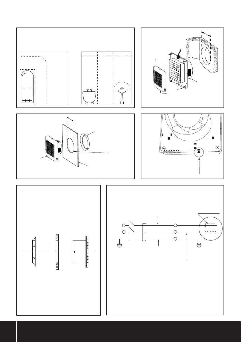
• Installieren Sie den Abluftventilator in der nach Raumgröße oder-bedingungen
zugelassenen höchsten Stelle.
• Verwenden Sie je nach Befestigungsart die für Wand- oder Fenstermontage
geeigneten Halterungen.
• Positionieren Sie den Ventilator so weit wie möglich von der Hauptluftquelle
(z.B. Türönung) entfernt, um den Luftstrom durch den Raum zu maximieren
Vorbereitung zur Wandmontage
WARNUNG! Vergewissern Sie sich, dass sich im vorgesehenen Montagebereich
der Innen- bzw. Außenwand keine Rohre, Leitungen oder Hindernisse benden.
Im Zweifelsfall wenden Sie sich an einen qualizierten Fachmann.
WARNUNG! Prüfen Sie vor dem Bohren, ob sich die Wandbeschaenheit für die
Installation eignet und den Bauvorschriften entspricht.
WICHTIG: Installieren Sie den Lüftungsschlauch in einem nach unten gerichteten,
vom Lüfter abweisenden Winkel, um sicherzustellen, dass Kondenswasser und
Wasser vom Lüfter abießen.
Installationsönung mit Kernbohrer bohren
1. Markieren Sie den Mittelpunkt der Installationsönung an der Innenwand.
2. Markieren Sie mit Hilfe des Mittelpunkts einen für den Lüftungsschlauch
passenden Kreis mit 115-mm-Durchmesser.
3. Folgen Sie den Anweisungen des Kernbohrer-Herstellers, um ein kreisförmiges
Loch in der Innenwand zu erstellen, und wiederholen Sie den Vorgang auf
der Außenwand.
4. Schneiden Sie den Lüftungsschlauch auf die gewünschte Länge zu.
5. Installieren Sie den Lüftungsschlauch.
6. Führen Sie notwendige Ausbesserungsarbeiten an der Wand durch, wie z.B.
das Ausfüllen von Lücken und xieren Sie den Lüftungsschlauch sicher an Ort
und Stelle.
Hinweis: Lassen Sie Füll- und Dichtungsmaterialien vollständig durchtrocknen,
bevor Sie mit der Installation des Abluftventilators fortfahren.
Bohrer und Meißelbohrung
1. Markieren Sie den Mittelpunkt der Installationsönung an der Innenwand.
2. Markieren Sie mit Hilfe des Mittelpunkts einen für den Lüftungsschlauch
passenden Kreis mit 115-mm-Durchmesser.
3. Bohren Sie eine einzelne Mittelbohrung durch die Wand, bis das Bohrloch auf der
Außenwand sichtbar ist.
4. Bohren Sie eine Reihe acherer Bohrlöcher um den Rand des Kreises herum,
achten Sie dabei darauf, dieWand nicht durchzubohren.
5. Verwenden Sie zur Entfernung von Mörtel zwischen den einzelnen Bohrungen
einen geeigneten Hand- oder Mörtelmeißel, um die Installationsönung an der
Innenwand zu erstellen.
6. Wiederholen Sie mit Hilfe der Mittelbohrung auf der Außenwand nun die Schritte
3 – 5, um die Installationsönung fertigzustellen.
7. Schneiden Sie den Lüftungsschlauch auf die gewünschte Länge zu.
8. Installieren Sie den Lüftungsschlauch.
9. Führen Sie notwendige Ausbesserungsarbeiten an der Wand durch,
wie z.B. das Ausfüllen von Lücken und xieren Sie den Lüftungsschlauch
sicher an Ort und Stelle.
Hinweis: Lassen Sie Füll- und Dichtungsmaterialien vollständig durchtrocknen,
bevor Sie mit der Installation des Abluftventilators fortfahren
Trennschutzschalter und Kabel anbringen
WARNUNG! Vergewissern Sie sich, dass die Stromversorgung während des
gesamten Installationsdurchgangs unterbrochen bleibt.
1. Trennen Sie die Stromversorgung.
2. Stellen Sie sicher, dass die elektrische Leistung des Abzugsventilators mit der
Netzversorgung übereinstimmt.
3. Achten Sie darauf, dass sich keine Leitungen und Rohre in unmittelbarer Nähe
des Trennschutzschalters benden. Im Zweifelsfall wenden Sie sich an einen
qualizierten Fachmann.
4. Installieren Sie den Trennschutzschalter und den Ein-/ Ausschalter sowie die
erforderlichen Kabel.
5. Stellen Sie die Verbindungen zwischen dem Trennschutzschalter und
dem Ein-/ Ausschalter her.
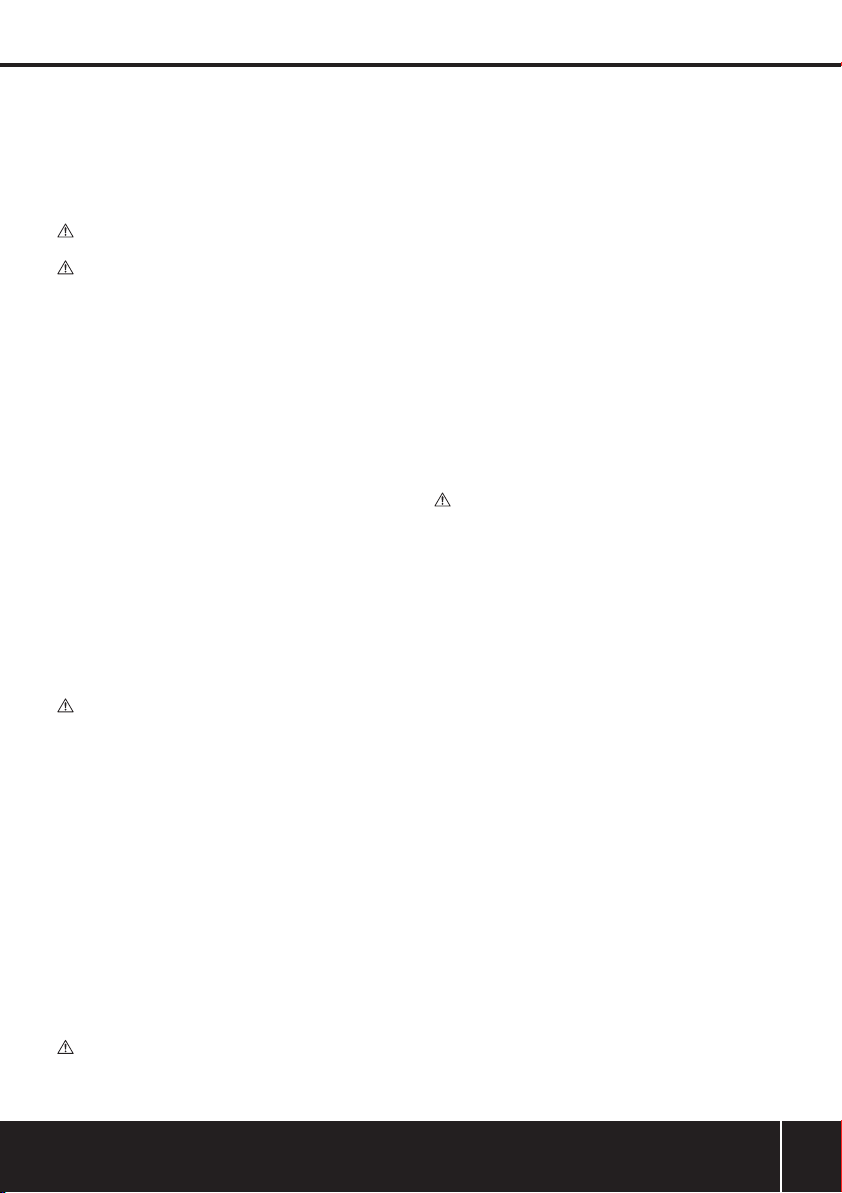
Wandmontage des Ventilators und der Rückplatte (Abb. II)
Positionierung der Rückplatte
1. Lösen Sie die Schraube auf der Unterseite des Abluftventilators und entfernen
Sie die Abdeckhaube (Abb. IV).
2. Vergewissern Sie sich, dass der Stutzen glatt und gratfrei ist.
3. Positionieren Sie die Rückplatte so, dass die Halteschraube der Abdeckhaube
nach unten zeigt.
4. Fügen Sie sie nun in die Installationsönung.
5. Achten Sie darauf, dass sich die Rückplatte im korrekten horizontalen
Winkel bendet.
6. Markieren Sie die Befestigungspunkte auf der Wand.
7. Entfernen Sie die Rückplatte.
8. Bohren Sie die Befestigungslöcher in die Wand und verwenden Sie geeignete
Wanddübel und Schrauben.
Befestigung der Rückplatte
1. Führen Sie die Kabel in die Anschlussklemmen des Ventilators
2. Setzen Sie die Rückplatte und den Stutzen in die Installationsönung, siehe
„Positionierung der Rückplatte“.
WARNUNG! Befestigen Sie den Lüftungsschlauch nicht zu fest an den Stutzen
der Rückplatte, da dies die Bewegung des Ventilators beeinträchtigen kann.
3. Fixieren Sie die Rückplatte mit Schrauben oder anderen geeigneten
Befestigungsmitteln an der Wand.
Hinweis: Ziehen Sie die Schrauben nicht zu fest an.
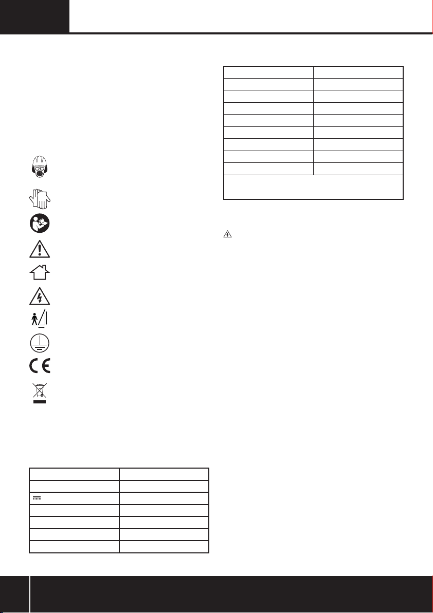
Fenstermontage des Ventilators und
der Rückplatte (Abb. III)
1. Schneiden Sie eine 103 mm große Önung in das Fensterglas
2. Lösen Sie die Schraube auf der Unterseite des Abluftventilators und entfernen
Sie die Abdeckhaube (Abb. IV).
3. Positionieren Sie die Rückplatte so, dass die Halteschraube der Abdeckhaube
nach unten zeigt.
4. Fügen Sie sie nun in die Installationsönung.
5. Achten Sie darauf, dass sich die Rückplatte im korrekten horizontalen
Winkel bendet.
6. Fixieren Sie den Befestigungsring von der anderen Seite des Fensterglases an
den Stutzen der Rückplatte (Abb. V).
7. Führen Sie die Kabel in die Anschlussklemmen des Ventilators.
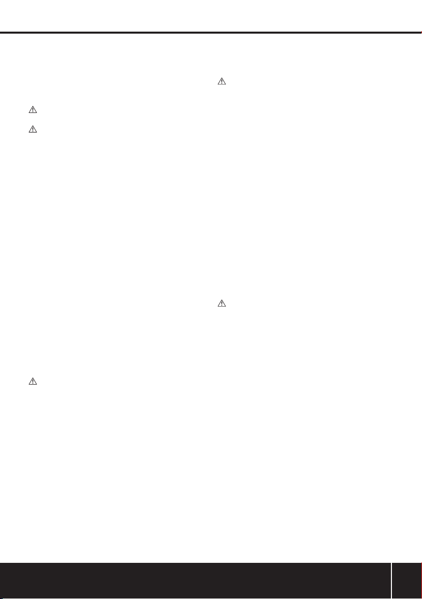
Elektrischer Anschluss (siehe Abb. VI)
1. Stellen Sie sicher, dass die Stromversorgung unterbrochen ist.
2. Schließen Sie die Stromkabel an die Anschlussklemmen des Ventilators an.
3. Setzen Sie die Abdeckhaube auf und schrauben diese fest (Abb. IV).
4. Schließen Sie den Trennschutzschalter an die Stromversorgung an.
5. Stellen Sie die Stromversorgung des Abluftventilators wieder her.
Hinweis: Sicherungen für fest angeschlossene Geräte dürfen 5 A
nicht überschreiten.
Betrieb
• Betreiben Sie den Abluftventilator über den Ein- /Ausschalter, z.B. einen
Lichtschalter oder einen unabhängigen Schalter.
Wartung und Pege
Reinigung
WARNUNG! Trennen Sie den Abluftventilator von der Stromversorgung, bevor
Sie Wartungs- oder Reinigungsarbeiten durchführen. Im Zweifelsfall wenden Sie
sich an einen qualizierten Kundendienst.
• Entfernen Sie die Abdeckhaube (Abb. IV) und reinigen Sie sie.
• Reinigen Sie Kunststoteile niemals mit Ätzmitteln. Falls eine Trockenreinigung
nicht ausreichend ist, sollte ein mildes Reinigungsmittel auf einem feuchten
Lappen verwendet werden.
• Vergewissern Sie sich vor dem erneuten Gebrauch, dass das Gerät wieder
vollkommen trocken ist.
Kontakt
Informationen zu Reparatur- und Kundendiensten erhalten Sie unter der
Rufnummer (+44) 1935/382222.
Webseite: https://www.plumbob.eu/de-DE/
Postanschrift:
Powerbox
Boundary Way
Lufton Trading Estate
Yeovil, Somerset
BA22 8HZ
Entsorgung
Beachten Sie bei der Entsorgung von defekten und nicht mehr reparablen
Elektrowerkzeugen die geltenden Vorschriften und Gesetze.
• Elektrowerkzeuge und andere elektrische und elektronische Altgeräte nicht über
den Hausmüll entsorgen.
• Lassen Sie sich von der zuständigen Behörde bezüglich der ordnungsgemäßen
Entsorgung von Elektrowerkzeugen beraten.
plumbob.eu
934172_Manual.indd 9 18/02/2019 09:44

10
ES
Instrucciones de seguridad
para extractores
ADVERTENCIA: Desconecte el extractor del suministro eléctrico antes de
instalarlo o realizar cualquier tarea de mantenimiento.
• Este producto está diseñado para ser instalado por un técnico cualicado.
• Se deben incluir instrucciones para desconectar el cableado jo. Las
instrucciones de cableado suministradas deberán seguir las normas de
conexionado vigentes.
• No realice ninguna conexión eléctrica con el extractor hasta completar
la instalación.
• Si el tubo de extracción se coloca más alto que el extractor, se debe colocar
una trampa de condensación lo más cerca posible del ventilador para evitar el
contacto del agua con el extractor.
• Este producto no está diseñado para su uso en temperaturas ambiente
superiores a 50° C.
• No utilice este producto para extraer los humos o vapores producidos por
dispositivos que queman combustible o aparatos no eléctricos.
• Para mayor seguridad, verique las normas de seguridad del edicio antes de
instalar el extractor en una habitación con un dispositivo con funcionamiento a
combustible o con chimenea. En caso de duda, consulte a un técnico cualicado.
• No coloque ningún interruptor de encendido/apagado cerca de personas que
usen una ducha o baño.
• Asegúrese de que la ubicación del extractor y los cambios estructurales en las
paredes y ventanas cumplan con las regulaciones vigentes. En caso de duda,
consulte a un profesional.
Aplicaciones
Extractor de baño para instalar en paredes o ventanas. Indicado para usar en baños,
lavaderos y lavabos. Este producto está indicado solamente para uso en baños
domésticos – zona 3 (Fig. I).
Desembalaje
• Desembale e inspeccione la herramienta con cuidado.
• Familiarícese con todas sus características y funciones.
• Asegúrese de que el embalaje incluya todas las piezas y compruebe que estén
en buenas condiciones.
• Si faltan piezas o están dañadas, sustitúyalas antes de utilizar esta herramienta.
Instalación
• Este extractor puede instalarse en la pared (Fig. II) o en la ventana (Fig. III).
• Use un cable bilar adecuado para conectar el ventilador a la fuente de
alimentación eléctrica.
• Compatible con tubos de extracción de 100 mm (4") (no incluido).
Traducción del manual original
Descripción de los símbolos
Los símbolos siguientes pueden aparecer en la placa de características de su
herramienta. Éstos representan información importante sobre el producto o
instrucciones relativas a su uso.
Lleve protección auditiva
Lleve protección ocular
Lleve protección respiratoria
Lleve un casco de seguridad
Lleve guantes de seguridad
Lea el manual de instrucciones
¡Peligro!
Solo para uso en interiores.
¡Riesgo de electrocución!
La posición correcta debe tener un ratio 1 x 4 (horizontal y vertical)
Protección clase I
Conforme a las normas de seguridad y la
legislación correspondiente.
Protección medioambiental
Los productos eléctricos usados no se deben mezclar con la basura
convencional. Por favor, recicle el producto en las instalaciones
correspondientes. Solicite información a su ayuntamiento o
distribuidor sobre las opciones de reciclaje.
Introducción
Gracias por adquirir este producto Plumbob. Estas instrucciones contienen la
información necesaria para utilizar este producto de forma segura y ecaz. Lea
atentamente este manual para obtener todas las ventajas y características únicas de
su nueva herramienta. Conserve este manual a mano y asegúrese de que todas las
personas que utilicen esta herramienta lo hayan leído y entendido correctamente.
4x
1x
Abreviaturas de términos técnicos
VVoltio/s
~, a.c. Corriente alterna
, d.c. Corriente continua
W, kW Vatio/s, kilovatio/s
dB(A) Nivel de decibelios (ponderada A)
l/s Litros por segundo
m3/hr Metros cúbicos por hora
Características técnicas
Tensión: 230 V, 50 Hz
Potencia: 12 W
Flujo de extracción: 18,33 l/s / 66 m3/h
Grado de protección: IPX0
Clase de protección: I
Nivel de ruido a 1 m: 45 dB(A)
Ancho del perl: 83 mm
Dimensiones (L x An x A): 150 x 100 x 150 mm
Peso: 0,45 kg
Como parte de nuestra política de desarrollo de productos, los datos técnicos
de los productos Plumbob pueden cambiar sin previo aviso.
934172_Manual.indd 10 18/02/2019 09:44

11
Montaje de la placa posterior
1. Introduzca los cables a través de los terminales del extractor.
2. Inserte la placa posterior y la espiga en el oricio de instalación, consulte
'Ubicación de la placa posterior'.
ADVERTENCIA: No apriete demasiado el tubo de extracción en la espiga de la
placa posterior, ya que puede restringir el movimiento del ventilador del extractor.
3. Fije la placa posterior en la pared utilizando tornillos o elementos
de jación apropiados.
Nota: No apriete los tornillos excesivamente.
Montaje en ventanas y la placa posterior
(ver Fig. III)
1. Realice un agujero de 103 mm de diámetro.
2. Retire la tapa frontal retirando el único tornillo en la parte inferior del ventilador
(Fig. IV).
3. Coloque la placa posterior de modo que el tornillo de sujeción de la tapa frontal
quede en la parte inferior.
4. Introduzca el extractor en el oricio de instalación.
5. Asegúrese de que la placa posterior esté en el ángulo horizontal apropiado.
6. Coloque el anillo de jación, en el otro lado del cristal, a la espiga de la placa
posterior (Fig. V).
7. Introduzca los cables a través de los terminales del extractor.
Conexión eléctrica (ver g. VI)
1. Asegúrese de que el suministro eléctrico principal esté desconectado.
2. Conecte los cables al extractor.
3. Vuelva a colocar la tapa frontal y el tornillo (Fig. IV).
4. Conecte el interruptor de aislamiento al suministro eléctrico.
5. Vuelva a conectar el suministro eléctrico al extractor.
Nota: Los fusibles para este aparato en circuitos de cableado jo nunca deben
superar los 5 A.
Funcionamiento
• Encienda y apague el extractor mediante el interruptor de encendido de las luces
del baño o mediante un interruptor independiente.
Mantenimiento
Limpieza
ADVERTENCIA: Asegúrese de desconectar el extractor de la fuente de
alimentación antes de instalar o realizar cualquier tipo de mantenimiento. En caso
de duda, consulte con un electricista.
• Retire la tapa frontal (Fig. IV) para limpiar este producto.
• Nunca utilice productos abrasivos, líquidos cáusticos o alcohol para
limpiar la tapa.
• Seque este producto antes de volver a utilizarlo.
Contacto
Servicio técnico de reparación Plumbob – Tel: (+44) 1935 382 222
Web: https://www.plumbob.eu/es-ES/
Dirección:
Powerbox
Boundary Way
Lufton Trading Estate
Yeovil, Somerset
BA22 8HZ, Reino Unido
Reciclaje
Deshágase siempre de las baterías y cargadores adecuadamente respetando las
normas de reciclaje indicadas en su país.
• No deseche las herramientas y aparatos eléctricos junto con la
basura convencional.
• Póngase en contacto con la autoridad local encargada de la gestión de
residuos para obtener más información sobre cómo reciclar este tipo de
herramientas correctamente.
Ubicación del extractor
• Instale el extractor a la altura máxima según el tamaño o las condiciones de la
zona de montaje.
• Instale el extractor de forma segura utilizando los accesorios adecuados para
adaptarse al material de la pared o ventana.
• Coloque el extractor a la distancia más alejada de la fuente principal de aire (por
ejemplo, una puerta) para maximizar el ujo de aire.
Preparación del agujero de la pared
ADVERTENCIA: Asegúrese de que no haya tuberías, cables u obstrucciones en
el interior o exterior de la pared. En caso de duda, consulte a un profesional.
ADVERTENCIA: Antes de perforar, verique que el material de la pared sea
adecuado para la instalación del ventilador y cumpla con las regulaciones vigentes.
IMPORTANTE: Coloque el tubo de extracción en un ángulo hacia abajo, lejos del
extractor para evitar la condensación y el agua cerca del extractor.
Perforación del oricio de extracción usando una corona perforadora
1. Marque el punto central de la posición del oricio de instalación en la pared.
2. Utilice el punto central para crear el círculo de 115 mm de diámetro adecuado
para el tubo de extracción.
3. Siga las instrucciones del fabricante de la corona perforadora para crear el oricio
circular en la pared interna, a continuación, repita el mismo procedimiento en la
pared externa.
4. Corte el tubo de extracción a la longitud requerida.
5. Coloque el tubo de extracción.
6. Haga las reparaciones necesarias en la pared para evitar huecos y jar el tubo de
extracción en el lugar requerido.
Nota: Deje que el cemento o mortero se seque antes de continuar con la
instalación del extractor.
Perforación del oricio de extracción usando una broca y cincel
1. Marque el punto central de la posición del oricio de instalación en la pared.
2. Utilice el punto central para crear el círculo de 115 mm de diámetro adecuado
para el tubo de extracción.
3. Perfore un oricio central a través de la pared para que el oricio sea visible en la
pared externa.
4. Perfore una serie de oricios poco profundos alrededor del borde del círculo de
la línea de corte, asegurándose de no perforar a través de la pared.
5. Utilice un cincel de albañil para retirar los restos de ladrillo situado entre los
agujeros para para poder crear un agujero en la pared interna.
6. Use el único oricio en la pared externa como guía para repetir el proceso
(consulte los pasos 3 a 5) para completar el oricio.
7. Corte el tubo de extracción a la longitud requerida.
8. Coloque el tubo de extracción.
9. Haga las reparaciones necesarias en la pared para evitar huecos y jar el tubo de
extracción en el lugar requerido.
Nota: Deje que el cemento o mortero se seque antes de continuar con la
instalación del extractor.
Interruptor de aislamiento y cables
ADVERTENCIA: No conecte el extractor al suministro eléctrico durante o
después de esta etapa.
1. Desconecte el suministro eléctrico.
2. Asegúrese de que la clasicación eléctrica del extractor coincida con las
especicaciones la fuente de alimentación.
3. Asegúrese de que no haya tuberías o cables cerca o detrás de la ubicación del
interruptor de aislamiento. En caso de duda, consulte a un electricista.
4. Instale el interruptor de aislamiento y el interruptor de encendido/apagado y los
cables necesarios.
5. Haga las conexiones dentro del interruptor de aislamiento y el interruptor de
encendido/apagado.
Montaje en pared y la placa posterior (Fig. II)
Ubicación la placa posterior
1. Retire la tapa frontal retirando el único tornillo en la parte inferior
del ventilador (Fig. IV).
2. Asegúrese de que el borde de la espiga sea liso y no tenga rebabas.
3. Coloque la placa posterior de modo que el tornillo de sujeción de la tapa
frontal quede en la parte inferior.
4. Introduzca el extractor en el oricio de instalación.
5. Asegúrese de que la placa posterior esté en el ángulo horizontal apropiado.
6. Marque las posiciones de los oricios de jación en la pared.
7. Retire la placa posterior del oricio de instalación.
8. Realice los oricios para tornillos en la pared. Utilice tacos de pared o accesorios
apropiados para el material requerido.
plumbob.eu
934172_Manual.indd 11 18/02/2019 09:44

12
IT Traduzione delle istruzioni originali
Descrizioni dei simboli
La targhetta sul dispositivo può mostrare dei simboli. Questi rappresentano
importanti informazioni sul prodotto o istruzioni sul suo utilizzo.
Indossare la protezione acustica
Indossare una protezione per gli occhi
Indossare una protezione respiratoria
Indossare un casco protettivo
Indossare la protezione delle mani
Leggere il manuale di istruzioni
Attenzione!
Uso solo interno
Rischio di fulminazione!
La posizione giusta della scala deve avere una angolo rispettando
un ratio di 1 (orizzontale) per 4 (verticale)
Costruzione di Classe (doppio isolamento per
protezione supplementare)
Conforme alla normativa e relative norme di sicurezza.
Tutela dell’ambiente
I riuti di apparecchiature elettriche non devono essere smaltiti con
i riuti domestici. Riciclare presso le strutture adeguate. Per ottenere
informazioni sul riciclaggio, contattare le autorità o il rivenditore locale.
Introduzione
Grazie per avere acquistato questo prodotto Plumbob. Questo manuale contiene
le informazioni necessarie per il funzionamento sicuro ed ecace di questo
prodotto. Questo prodotto ha caratteristiche uniche e, anche se si ha familiarità con
prodotti simili, è necessario leggere attentamente questo manuale per assicurarsi
di comprendere appieno le istruzioni. Assicurarsi che tutti gli utenti del prodotto
leggano e comprendano pienamente questo manuale.
4x
1x
Legenda delle
abbreviazioni tecniche
VVolt
~, c.a. Corrente alternata
, c.c. Corrente continua
W, kW Watt, Kilowatt
dB(A) Livello sonoro in decibel (A ponderato)
l/s Litri al secondo
m3/h Metri cubi per ora
Sicurezza dell’aspiratore
ATTENZIONE: Scollegare l'alimentazione dall'interruttore di servizio
prima di interventi di installazione o riparazione
• Questo prodotto deve essere installato da una persona qualicata
• I mezzi per lo scollegamento devono essere incorporati nel cablaggio sso
secondo le norme di cablaggio vigenti
• NON collegare l’aspiratore a connessioni elettriche vive no a
installazione completata
• Se il condotto è posizionato più in alto dell’aspiratore, un sistema di raccolta
della condensa deve essere installato il più vicino possibile all’aspiratore, per
evitare che l’umidità entri a contatto con le parti elettriche
• Questo prodotto non può essere usato in ambienti con temperature
superiori a 50°C
• NON utilizzare il prodotto per estrarre fumi o vapori prodotti dalla combustione
di carburante o da applicazioni non elettriche
• Controllare le norme vigenti prima dell’installazione dell’aspiratore in una stanza
con un apparecchio che brucia carburante o che produce gas di scarico. Se si
hanno dei dubbi, consultare un tecnico qualicato
• Non posizionare nessun interruttore ON/OFF vicino a doccia o vasca da bagno
• Assicurarsi che la posizione dell’aspiratore e i cambiamenti strutturali di mura
e nestre osservino le norme vigenti di costruzione. Se si hanno dei dubbi,
consultare un tecnico qualicato
Uso previsto
Aspiratore da montare a pareti sottili, nestre e pannelli, adatto a bagni, ripostigli e
servizi igenici. L’aspiratore è destinato all’uso domestico in bagni, SOLO in
zona 3 (Fig. I).
Disimballaggio del prodotto
• Disimballare e ispezionare con cautela il prodotto
• Familiarizzare con tutte le sue caratteristiche e funzioni
• Assicurarsi che tutte le parti del prodotto siano presenti e in buone condizioni
• Se delle parti sono mancanti o danneggiate, sostituirle prima di tentare di
utilizzare questo prodotto
Installazione
• L’aspiratore è adatto al ssaggio a muro (Fig. II) o su una nestra (Fig. III)
• Utilizzare cavi elettrici bipolari adatti all’installazione alla sorgente principale
di corrente
• Supporta condotti da 100 mm (non inclusi)
Posizione dell’aspiratore
• Installare l’aspiratore alla massima altezza permessa dalle dimensioni e la
disposizione della stanza
• Installare l’aspiratore in modo sicuro usando le attrezzature adatte al materiale
del muro o della nestra
• Posizionare l’aspiratore alla distanza maggiore possibile dall’altra fonte di entrata
di aria nella stanza (per esempio, una porta) per massimizzare il ricambio d’aria
Speciche tecniche
Tensione: 230V~ 50Hz
Potenza: 12 W
Portata di estrazione: 18.33l/s / 66m3/h
Protezione ingresso: IPX0
Classe elettrica: I
Livello sonoro a 1m: 45dB(A)
Prolo di profondità: 83 mm
Dimensioni (L x P x A): 150 x 100 x 150mm
Peso: 0,45 kg
Nell’ambito del nostro continuo sviluppo del prodotto, le speciche tecniche
dei prodotti Plumbob possono subire variazioni senza preavviso.
934172_Manual.indd 12 18/02/2019 09:44

13
Preparazione del foro da muro
AVVERTENZA: Assicurarsi che non ci siano tubature, cavi o ostruzioni nella
parte interna o esterna dell’aria di installazione. Se si hanno dei dubbi, consultare
un tecnico specializzato.
AVVERTENZA: Prima di trapanare, controllare che il materiale della parete sia
adatto all’installazione di aspiratori e rispetti le norme vigenti
IMPORTANTE: Installare il condotto ad un’angolazione che va verso il basso, così da
assicurarsi che la condensa e l’umidità drenino lontano dall’aspiratore.
Forare con la carotatrice
1. Segnare il punto centrale del foro di installazione sul muro interno
2. Usare il punto centrale per creare un cerchio di diametro 115 mm adatto
al condotto
3. Seguire le istruzioni della carotatrice come da manuale del produttore, per
creare un foro circolare sulla parete interna, poi ripetere l’operazione sulla
parete esterna
4. Tagliare il condotto alla lunghezza richiesta
5. Installare il condotto
6. Riparare il muro dove necessario per evitare spazi vuoti e ssare il
condotto in postazione
Nota bene: Se si usano materiali di riempimento o malta, lasciare asciugare prima
dell’installazione.
Forare con trapano a punta e scalpello
1. Segnare il punto centrale del foro di installazione sul muro interno
2. Usare il punto centrale per creare un cerchio di diametro 115 mm adatto
al condotto
3. Creare un foro centrale con il trapano attraverso il muro cosicchè sia visibile
dalla parte esterna
4. Creare una serie di fori poco profondi intorno al foro centrale, assicurandosi di
non trapanare attraverso il muro
5. Usare uno scalpello da muratore o uno scalpello per scalanatura per rimuovere
i mattoni tra i fori già creati, per formare un foro sulla parete interna
6. Usare il foro singolo sul muro esterno come guida per ripetere il processo
(vedi punti da 3 a 5) e completare il foro più grande
7. Tagliare il condotto alla lunghezza desiderata
8. Installare il condotto
9. Riparare il muro dove necessario per evitare spazi vuoti e ssare il
condotto in postazione
Nota bene: Se si usano materiali di riempimento o malta, lasciare asciugare prima
dell’installazione.
Isolare interruttori e cavi
AVVERTENZA: Non connettere sorgenti elettriche durante o dopo questa fase.
1. Isolare la sorgente elettrica
2. Assicurarsi che le caratteristiche elettriche dell’aspiratore siano adatte alla
sorgente elettrica principale
3. Assicurarsi che non ci siano tubature o cavi vicino o dietro all’interruttore isolato.
Se si hanno
dei dubbi, contattare un elettricista qualicato.
4. Installare l’interruttore ON/OFF, e i cavi necessari
5. Connettere l’interruttore isolato all’interruttore ON/OFF
Fissare l’aspiratore e la piastra
posteriore al muro (Fig. II)
Posizionare la piastra posteriore
1. Rimuovere la copertura frontale (Fig. IV)
2. Assicurarsi che le estremità del raccordo siano lisce e prive di bave
3. Posizionare la piastra posteriore cosicchè le viti siano ssate alla base della
copertura frontale
4. Inserire al foro di installazione
5. Assicurarsi che la piastra posteriore sia ad un angolo orizzontale appropriato
6. Segnare la posizione del foro sul muro
7. Rimuovere la piastra posteriore dal foro di installazione
8. Fissare le viti con il trapano e usare prese da muro o appropriate al materiale,
se necessario
Fissare la piastra posteriore
1. Far passare i cavi attraverso i terminali dell’aspiratore
2. Inserire la piastra posteriore e il raccordo nel foro di installazione, vedi sezione
“posizionare la piastra posteriore”
AVVERTENZA: Non ssare il condotto troppo stretto al raccordo della piastra
posteriore, potrebbe ostruire i movimenti dell’aspiratore
3. Assicurare l’aspiratore al muro con le viti o il metodo più appropriato,
se necessario
Nota bene: Non ssare le viti troppo strette.
Fissare l’aspiratore e la piastra posteriore
a una nestra (vedi Fig. III)
1. Tagliare un foro di diametro 103 mm
2. Rimuovere la piastra posteriore attraverso la rimozione della vite singola
alla base (Fig. IV)
3. Posizionare la piastra posteriore cosicchè le viti siano ssate alla base della
copertura frontale
4. Inserire al foro di installazione
5. Assicurarsi che la piastra posteriore sia ad un angolo orizzontale appropriato
6. Fissare la ghiera di ssaggio, dalla parte opposta del vetro, al raccordo della
piastre posteriore (Fig. V)
7. Far passare i cavi attraverso i terminali dell’aspiratore
Connessioni elettriche (vedi Fig. VI)
1. Assicurarsi che la sorgente di elettricità principale sia isolata
2. Connettere i cavi all’aspiratore
3. Fissare di nuovo la copertura frontale sostituendo le viti (Fig. IV)
4. Connettere la presa isolata alla sorgente di elettricità principale
5. Riconnettere l’elettricità all’aspiratore
Nota bene: I fusibili per questo dispositivo non devono eccedere 5 A in circuiti a
cablaggio sso.
Funzionamento
• Accendere l’aspiratore con l’interruttore ON/OFF, come si farebbe con una presa
della luce.
Manutenzione
Pulizia
AVVERTENZA: Assicurarsi che l'aspiratore sia scollegato dalla sorgente di
elettricità principale prima di interventi di pulizia e manutenzione. Se si hanno dei
dubbi, consultare un tecnico specializzato.
• Rimuovere la copertura frontale (Fig. IV) per pulire
• Non usare sostanze abrasive, liquidi caustici o alcol per pulire le parti.
Se la pulitura a secco non è abbastanza, stronare con un panno umido
e detergente delicato.
• Lasciare asciugare prima di riposizionarlo
Contatti
Per assistenza tecnica o riparazioni, contattare il Servizio Clienti al
numero (+ 44) 1935 382 222
Sito Web: https://www.plumbob.eu/it-IT/
Indirizzo:
Powerbox
Boundary Way
Lufton Trading Estate
Yeovil, Somerset
BA22 8HZ, Regno Unito
Smaltimento
Rispettare sempre le normative nazionali per lo smaltimento dei prodotti elettrici
che non sono più funzionali e non sono vitali per la riparazione.
• Non gettare utensili elettrici, o altri riuti di apparecchiature elettriche ed
elettroniche (RAEE), con i riuti domestici
• Contattare l'autorità locale di smaltimento riuti per informazioni sul modo
corretto di smaltire elettroutensili o apparecchiature elettriche ed elettroniche.
plumbob.eu
934172_Manual.indd 13 18/02/2019 09:44

14
NL
Veiligheid extractieventilator
WAARSCHUWING: Koppel de voeding steeds ter hoogte van de
hoofdschakelaar los alvorens het apparaat te installeren of te repareren
• Dit product dient geïnstalleerd te worden door een gekwaliceerde monteur
• Middelen om de voeding los te koppelen dienen opgenomen te zijn in de vaste
bedrading, in overeenstemming met de huidige regelgeving met betrekking
tot de bedrading
• Breng geen onder spanning staande verbinding met de ventilator tot stand
alvorens de installatie volledig is afgerond
• Indien er leidingen hoger dan de ventilator gepositioneerd zijn, dient er zo dicht
mogelijk bij de ventilator een condensatieval aangebracht te worden om de
indringing van water te voorkomen.
• Dit product is niet bedoeld om gebruikt te worden in omgevingstemperaturen
die hoger liggen dan 50 ºC.
• Gebruik dit product niet om gassen of dampen af te voeren die het gevolg zijn
van de werking van een brander of van niet-elektrische apparaten.
• Controleer de veiligheidsvoorschriften van het gebouw alvorens de
extractieventilator te installeren in een ruimte waarin een inrichting aanwezig is
die brandstof verbrandt en dus rookgassen produceert. Indien u twijfelt, neem
dan contact op met een gekwaliceerde servicetechnicus.
• Plaats geen AAN/UIT-schakelaars binnen handbereik van personen die een
douche of een bad nemen.
• Zorg ervoor dat de plaats van opstelling van de ventilator en eventuele
structurele wijzigingen in wanden en vensters voldoen aan eventuele
bouwregelgeving. Indien u twijfelt, neem dan contact op met een expert.
Voorzien gebruik
Afzuigventilator met een enkele snelheid, te monteren in een wand, venster, of
paneel, geschikt voor badkamers, faciliteitsruimten, en wc´s. Deze ventilator is
enkel bedoeld voor huishoudelijk gebruik in badkamerzone 3 (Afb. I).
Het uitpakken van
uw gereedschap
• Pak uw toestel/gereedschap uit.
• Inspecteer het en zorg dat u met alle kenmerken en functies vertrouwd raakt.
• Controleer of alle onderdelen aanwezig zijn en in goede staat verkeren.
• Als er onderdelen ontbreken of beschadigd zijn, zorg dan dat deze vervangen
worden voor u dit toestel/gereedschap gebruikt.
Installatie
• De extractieventilator is geschikt voor montage in of op de wand (afb. II) of in
een venster (afb. III).
• Gebruik de juiste 2-aderige kabels om de ventilator te verbinden met de
elektrische voeding.
• Geschikt voor 100 mm leiding (niet meegeleverd)
Vertaling van de originele instructies
Beschrijving symbolen
Op het typeplaatje van uw gereedschap kunnen symbolen voorkomen. Deze
vertegenwoordigen belangrijke informatie met betrekking tot het product of
instructies met betrekking tot het gebruik ervan.
Draag gehoorbescherming
Draag een veiligheidsbril
Draag een stofmasker
Draag een veiligheidshelm
Draag handschoenen
Lees de handleiding
Voorzichtig!
Enkel geschikt voor binnen gebruik!
Gevaarlijke elektrische spanning!
De juiste ladderhoek: 4 stappen omhoog, 1 stap uitwaards
Beschermingsklasse I (aardgeleiding)
Voldoet aan de relevante wetgeving en veiligheidsnormen
Milieubescherming
Elektrische producten mogen niet met het normale huisvuil worden
weggegooid. Indien de mogelijkheid bestaat, dient u het product
te recyclen. Vraag de plaatselijke autoriteiten of winkelier om advies
betreende recyclen.
Inleiding
Hartelijk dank voor de aanschaf van dit Plumbob-product. Deze instructies bevatten
informatie die u nodig hebt voor een veilige en doeltreende bediening van dit
product. Dit product heeft een aantal unieke eigenschappen. Lees deze handleiding
aandachtig door, ook al bent u bekend bent met soortgelijke machines, zodat u alle
voordelen van dit unieke ontwerp kunt benutten. Houd deze handleiding bij de
hand en zorg ervoor dat alle gebruikers van dit gereedschap de handleiding voor
gebruik hebben gelezen en volledig hebben begrepen.
4x
1x
Technische afkortingen
en symbolen
VVolt
~, a.c. Wisselspanning
, d.c. Gelijkspanning
W, kW Watt, kilowatt
dB(A) Decibel geluidsniveau (A-gewogen)
l/s Liters per seconde
m3/hr Kubieke meter per uur
Specicaties
Spanning: 230 V~50 Hz
Vermogen: 12 W
Extractiedebiet: 18,33 l/s / 66 m3/hr
Beschermingsgraad: IPX0
Beschermingsklasse: I
Geluidsniveau op 1 m: 45 dB(A)
Proeldiepte: 83 mm
Afmetingen (L x B x H): 150 x 100 x 150 mm
Gewicht: 0,45 kg
In het kader van onze voortgaande productontwikkeling kunnen
de specicaties van Plumbob-producten zonder voorafgaande
kennisgeving worden gewijzigd.
934172_Manual.indd 14 18/02/2019 09:44

15
Op de wand of muur bevestigen van de
ventilator en de rugplaat (afb. II)
Positioneren van de rugplaat
1. Verwijder de voorste afdekking door de enige schroef onderaan de ventilator
te verwijderen (afb. IV)
2. Zorg ervoor dat de rand glad is en vrij van bramen
3. Plaats de rugplaat op een zodanige wijze dat de schroef die de voorste
afdekking vasthoudt, zich onderaan bevindt
4. Positioneer in het installatiegat
5. Zorg ervoor dat de rugplaat zich onder de vereiste horizontale hoek bevindt
6. Verbind de bevestigingsring, langs de andere zijde van het glas, op de
rugplaat (afb. V)
7. Breng de kabels aan door de klemmen van de ventilator
Elektrische verbindingen (zie afb. VI)
1. Zorg ervoor dat de elektrische voeding is geïsoleerd
2. Verbind de kabels met de ventilator
3. Breng de voorste afdekking opnieuw aan met behulp van de schroef (afb. IV)
4. Verbind de isolatieschakelaar met de voeding
5. Verbind de elektrische voeding opnieuw met de extractieventilator
Opmerking: De zekeringen voor het apparaat mogen niet hoger zijn dan 5 A in
circuits met vaste bedrading.
Werking
• Gebruik de extractieventilator met behulp van de AAN/UIT-schakelaar, net zoals
een lichtschakelaar.
Onderhoud
Schoonmaak
WAARSCHUWING: Isoleer de ventilator van de elektrische voeding alvorens
hem schoon te maken of te repareren. Indien u twijfelt, neem dan contact op met
een gekwaliceerde servicetechnicus.
• Verwijder de voorste afdekking (afb. IV) om schoon te maken
• Gebruik nooit bijtende middelen om plastic onderdelen schoon te maken. Indien
een droge schoonmaak niet voldoende is, verdient een zachte detergent op een
vochtige doek de voorkeur
• Droog grondig alvorens opnieuw te monteren.
Contact
Voor technische ondersteuning of voor reparatieadvies, gelieve contact op te
nemen met de hulplijn op (+44) 1935 382 222
Web: https://www.plumbob.eu/nl-NL/
Adres:
Powerbox
Boundary Way
Lufton Trading Estate
Yeovil, Somerset
BA22 8HZ, Verenigd Koninkrijk
Afvoer
Bij het buiten gebruik stellen en de afvoer van elektrische machines die niet
langer werken en die niet gerepareered kunnen worden, neemt u de nationale
voorschriften in acht
• Elektrische en elektronische apparaten (WEEE) mogen niet met huishoudelijk
afval worden weggegooid
• Neem contact op met uw gemeente voor informatie betreende de verwijdering
en afvoer van elektrisch gereedschap
Positie extractieventilator
• Installeer de extractieventilator op de maximale hoogte die de grootte van de
ruimte of de omstandigheden toestaat of toestaan.
• Breng de ventilator correct aan door gebruik te maken van bevestigingsmiddelen
die geschikt zijn voor het materiaal van de wand of het venster.
• Positioneer de extractieventilator zo ver mogelijk verwijderd van de hoofdbron
van luchtverversing (bijvoorbeeld een deur) om zodoende de luchtstroming
door de ruimte te maximaliseren.
Voorbereiding opening in de muur of wand
WAARSCHUWING: Zorg ervoor dat er geen buizen, kabels, of obstructies
aanwezig zijn, inwendig of uitwendig aan de beoogde installatieplaats. Indien u
twijfelt, neem dan contact op met een expert.
WAARSCHUWING: Alvorens te boren, dient u te controleren of het materiaal
van de wand of muur geschikt is voor de installatie van de ventilator en voldoet
aan de regelgeving.
BELANGRIJK: Breng leiding aan onder een neerwaartse helling, weg van de
ventilator, teneinde er zeker van te zijn dat eventuele condensatie en water de
ventilator niet kunnen bereiken.
Aanbrengen van de opening met behulp van een kernboor
1. Markeer het centrum van de installatieopening op de interne wand of muur.
2. Gebruik het centrum om een cirkel met een diameter van 115 mm te creëren
voor de leiding.
3. Volg de instructies van de producent van de kernboor om het cirkelvormige gat
aan te brengen in de interne wand of muur, en doe vervolgens hetzelfde voor de
externe wand of muur.
4. Zaag de leiding op de vereiste lengte af.
5. Plaats de leiding.
6. Voer de nodige herstellingen uit aan de muur of wand om spleten en openingen
weg te werken, en bevestig de leiding stevig op haar plaats.
Opmerking: Laat plamuur of mortel uitharden alvorens de installatie van de
ventilator verder te zetten.
Aanbrengen van het gat met behulp van een boorbit en beitel
1. Markeer het centrum van de installatieopening op de interne wand of muur.
2. Gebruik het centrum om een cirkel met een diameter van 115 mm te creëren
voor de leiding.
3. Boor een enkel gat door de muur of wand, zodat het gat zichtbaar is op de
externe wand of muur.
4. Boor een reeks ondiepe gaten rond de rand van de snijcirkel, waarbij u erop
dient te letten dat er niet door de wand of muur wordt geboord.
5. Gebruik een geschikte beitel om het materiaal tussen de geboorde gaten te
verwijderen, om zodoende een gat in de interne wand of muur te creëren.
6. Gebruik het enkele gat in de externe wand of muur als geleiding om het proces
te herhalen (zie stappen 3-5) om het gat volledig te maken.
7. Zaag de leiding op de vereiste lengte af.
8. Plaats de leiding.
9. Voer de nodige herstellingen uit aan de muur of wand om spleten en openingen
weg te werken, en bevestig de leiding stevig op haar plaats.
Opmerking: Laat plamuur of mortel uitharden alvorens de installatie van de
ventilator verder te zetten.
Isolatieschakelaar en kabels
WAARSCHUWING: Verbind geen elektrische voeding tijdens of na deze fase.
1. Isoleer de elektrische voeding
2. Vergewis u ervan dat de elektrische kenmerken van de extractieventilator
overeenstemmen met deze van de voeding
3. Zorg ervoor dat er geen buizen of kabels aanwezig zijn in de buurt van of achter
de plaats van de isolatieschakelaar. Indien u twijfelt, neem dan contact op met
een expert.
4. Instaleer de isolatieschakelaar en de aan/UIT-schakelaar alsook de vereiste kabels
5. Breng de verbindingen tot stand in de isolatieschakelaar
en de AAN/UIT-schakelaar
plumbob.eu
934172_Manual.indd 15 18/02/2019 09:44

16
PL
Opis symboli
Tabliczka znamionowa na narzędziu może zawierać pewne symbole.Symbolizują
one określone informacje o produkcie lub przedstawiają
instrukcje jego użycia.
Należy nosić środki ochrony słuchu
Należy nosić okulary ochronne
Należy nosić środki ochrony dróg oddechowych
Należy używać kasku ochronnego
Należy nosić rękawice ochronne
Należy w całości przeczytać instrukcję obsługi
Uwaga!
Wyłącznie do użytku w pomieszczeniach
Ryzyko porażenia prądem!
Prawidłowy kąt wznoszenia wynosi 1 na zewnątrz i 4 na górę
Konstrukcja klasy I (podwójnie izolowana w celu
dodatkowej ochrony)
Urządzenie zgodne z odpowiednimi przepisami
i normami bezpieczeństwa.
Ochrona środowiska
Nie należy wyrzucać zużytych produktów elektrycznych wraz
z odpadami komunalnymi. Jeśli jest to możliwe, należy przekazać
produkty do punktu recyklingu. W celu uzyskania wskazówek
dotyczących recyklingu należy skontaktować się z władzami lokalnymi
lub sprzedawcą.
Wprowadzenie
Dziękujemy za zakup produktu marki Plumbob. Niniejsza instrukcja obsługi zawiera
informacje niezbędne dla bezpiecznej i wydajnej obsługi produktu. Produkt posiada
szereg unikalnych funkcji, dlatego też, nawet jeśli jesteś zaznajomiony z podobnymi
produktami, przeczytanie tego podręcznika jest niezbędne w celu pełnego
zrozumienia instrukcji obsługi. Upewnij się, że wszyscy użytkownicy narzędzia
przeczytali i w pełni zrozumieli instrukcję obsługi.
Bezpieczeństwo korzystania
z wentylatora
OSTYRZEŻENIE : Należy pamiętać, aby zawsze odłączyć zasilanie przed
przystąpieniem do instalacji , bądź serwisem.
• Ten produkt jest przeznaczony do instalacji przez wykwalikowanego
pracownika serwisowego
• Środki do odłączenia muszą zostać włączone do stałego okablowania zgodnie z
aktualnymi przepisami dotyczącymi okablowania
• Nie wykonuj żadnych elektrycznych połączeń z wentylatorem wyciągowym,
dopóki instalacja nie zostanie zakończona
• Jeśli kanał jest położony wyżej niż wentylator wyciągowy, pułapka kondensatu
musi być zamontowana jak najbliżej wentylatora, aby zapobiec przedostawaniu
się wody
• Ten produkt nie jest przeznaczony do użytku w temperaturach otoczenia
przekraczających 50 ° C
• Nie należy używać tego produktu do odprowadzania spalin lub oparów
wytwarzanych przez urządzenia do spalania paliwa lub urządzeń
nieelektrycznych
• Sprawdź przepisy bezpieczeństwa budynku przed instalacją wentylatora
wyciągowego w pomieszczeniu z urządzeniem do spalania paliwa i spalin, aby
zapewnić maksimum bezpieczeństwa. W razie wątpliwości skonsultuj się z
wykwalikowanym pracownikiem serwisu
• Nie umieszczaj żadnych włączników ON / OFF w odległości od osób Urządzenia
odcinające zasilane muszą zostać włączone do stałego okablowania zgodnie z
aktualnymi przepisami dotyczącymi instalacji elektrycznych
Zastosowanie zgodne
z przeznaczeniem
Pojedynczej prędkości wentylator do montażu na ścianie, oknie bądź panelu w
łazienkach, toaletach, bądź pomieszczeniach gospodarczych. Niniejszy produkt jest
przeznaczony do domowego użytku, wyłącznie w stree łazienkowej 3 (Rys. I).
Rozpakowanie urządzenia
• Ostrożnie rozpakuj i sprawdź produkt.
• Zapoznaj się ze wszystkimi mechanizmami i funkcjami.
• Upewnij się, że produkt zawiera wszystkie części i są one w dobrym stanie.
• Jeśli brakuje pewnych części lub są one uszkodzone, należy uzupełnić lub
wymienić je przed rozpoczęciem korzystania z produktu.
Instalacja
• Wentylator jest przeznaczony do montażu na ścianie (Rys. II), bądź oknie (Rys. III)
• Użyj dwużyłowego kabla w celu podłączenia wentylatora do źródła zasilania
• Pasuje do kanału wielkości 100 mm (4") (brak w zestawie)
Tłumaczenie oryginalnej instrukcji
4x
1x
Kluczowe skróty techniczne
VWolt
~, a.c. Prąd przemienny
, d.c. Prąd stały
W, kW Wat, kilowat
dB(A) Poziom hałasu w decybelach
(A mierzony)
l/s Litry na sekundę
m3/hr Metry sześcienne na godzinę
Dane techniczne
Napięcie: 230 V ~ 50 Hz
Zasilanie: 12 W
Wskaźnik ekstrakcji: 18,33 l/s / 66 m3/hr
Stopień ochrony IP: IPX0
Klasa ochrony I
Poziom hałasu w odległości 1 m: 45 dB (A)
Głębokość prolu: 83 mm
Wymiary (Dł. x Szer. xWys.): 150 x 100 x 150mm
Waga: 0,45 kg
W wyniku nieprzerwanego procesu rozwojowego produktów specykacje
produktów Plumbob mogą ulec zmianie bez uprzedniego powiadomienia.
934172_Manual.indd 16 18/02/2019 09:44

17
Lokalizacja wentylatora
• Zainstaluj wentylator na maksymalnej wysokości pokoju, bądź na tyle ile
warunki pozwalają
• Zamontuj wentylator korzystając z odpowiedniego mocowania, przeznaczonego
do ściany, bądź okna
• Ustaw wentylator możliwie najdalej od źródła wymiany powietrza (np. drzwi),
aby zmaksymalizować przepływ powietrza w pomieszczeniu
Przygotowanie otworu w ścianie
OSTRZEŻENIE: Upewnij się, że w ścianie nie ma żadnych rur, kalbi ani innych
przeszkód wewnątrz i na zewnątrz ściany, na której ma być zainstalowany produkt.
W razie wątpliwości, należy się skonsultować z wykwalikowaną osobą.
OSTRZEŻENIE: Przed przystąpieniem do wiercenia, sprawdź czy, materiał,
z którego jest wykonana ściana nadaje się do montażu wentylatora i jest zgodny
z regulaminem.
WAŻNE: Dopasuj kanał pod kątem skierowanym w dół od wentylatora, aby
zapewnić kondensację i odprowadzenie wody z wentylatora.
Wykonanie otworu przy użyciu wiertła rdzeniowego
1. Zaznacz środek otworu, który ma być nawiercony na wewnętrznej części ściany
2. Przy użyciu punktu środkowego stwórz okrąg o średnicy 115 mm odpowiedni
dla kanału
3. Postępuj zgodnie z instrukcjami producenta wiertła rdzeniowego, aby
wykonać okrągły otwór na wewnętrznej ścianie, po czym powtórz kroki
na zewnętrznej ścianie
4. Wytnij kanał na wymaganą długość
5. Umieść kanał
6. Wykonaj niezbędne naprawy w ścianie, aby zapobiec powstawaniu szczelin i
zabezpieczyć kanał
Uwaga: Odczekaj, aż wypełniacze, bądź tynk wyschną przed kontynuowaniem
instalacji wentylatora.
Wykonanie otworu przy użyciu wiertła i dłuta
1. Zaznacz środek otworu, który ma być nawiercony na wewnętrznej części ściany
2. Przy użyciu punktu środkowego stwórz okrąg o średnicy 115 mm odpowiedni
dla kanału
3. Wywierć jeden otwór przez całą grubość ściany, tak, aby była widoczna po
drugiej stronie
4. Wykonaj serię płytkich otworów na granicy średnicy otworu, upewniając się, że
nie nawiercamy całej grubości ściany
5. Użyj przecinaka murarskiego, bądź dłuta do usuwania starej zaprawy, aby usunąć
tynk znajdujący się pomiędzy nawierconymi otworami do stworzenia otworu na
kanał w wewnętrznej ścianie
6. Użyj pojedynczego otworu w zewnętrznej części ściany, aby powtórzyć cały
proces (patrz kroki 3 – 5) do wykonania kanału
7. Wytnij kanał na wymaganą długość
8. Umieść kanał
9. Wykonaj niezbędne naprawy w ścianie, aby zapobiec powstawaniu szczelin i
zabezpieczyć kanał
Uwaga: Odczekaj, aż wypełniacze, bądź tynk wyschną przed kontynuowaniem
instalacji wentylatora.
Wyłącznik i przewody izolacyjne
OSTRZEŻENIE: Nie należy podłączać źródła zasilania podczas, bądź po
zakończeniu tych kroków.
1. Odłącz zasilanie sieciowe
2. Upewnij się, że parametry elektryczne wentylatora jak i zasilania sieciowego
są odpowiednie
3. Upewnij się, że żadne rury ani kable nie znajdują się za wyłącznikiem. W razie
jakichkolwiek wątpliwości należy się skonsultować z wykwalikowaną osobą
4. Zamontuj wyłącznik wraz z przełącznikiem On/O oraz konieczne kable
5. Połącz ze sobą wyłącznik sieciowy oraz przełącznik On/O
Montaż wentylatora w ścianie oraz
tylnej płytki (Rys. II)
Ustawienie tylnej płytki
1. Zdejmij przednią osłonę poprzez wykręcenie pojedynczego wkrętu na dole
wentylatora (Rys. IV)
2. Upewnij się, że krawędzie króćca są gładkie bez zadziorów
3. Ustaw tylną płytkę, tak aby przednia osłona trzymała dolny wkręt
4. Umieść w otworze instalacyjnym
5. Upewnij się, że tylna płytka znajduje się pod odpowiednim kątem nachylenia
6. Zaznacz otwór do mocowania na ścianie
7. Zdejmij tylna płytkę z otworu instalacyjnego
8. Nawierć otwory w ścianie korzystając z zatyczek do kołków, bądź
odpowiednich mocowań przeznaczonych do materiału, na którym ma
być zamontowany wentylator
Montaż tylnej płytki
1. Zdejmij pokrywę i wsuń kable przez terminale wentylatora
2. Umieść tylną płytkę oraz króciec w otworze instalacyjnym, patrz podrozdział
“ustawienie tylnej płytki”
OSTRZEŻENIE: Nie należy zbyt mocno dokręcać kanału do króćca tylnej płytki,
może to doprowadzić do ruszania się wentylatora.
3. Przymocuj tylną płytkę korzystając z wkrętów przeznaczonych do użycia w
ścianie, bądź podobnego mocowania
Uwaga: Nie dokręcaj zbyt mocno wkrętów.
Montaż wentylatora oraz tylnej płytki w oknie
(patrz Rys. III)
1. Wytnij otwór o średnicy 103 mm
2. Zdejmij przednią osłonę poprzez wykręcenie pojedynczego wkrętu na dole
wentylatora (Rys. IV)
3. Ustaw tylna płytkę, tak aby przednia osłona trzymała dolny wkręt
4. Umieść w otworze instalacyjnym
5. Upewnij się, że tylna płytka znajduje się pod odpowiednim kątem nachylenia
6. Podłącz pierścień mocujący, po drugiej stronie szyby, do króćca tylnej
płytki (Rys. V)
7. Wprowadź kable przez terminale wentylatora
Podłączenie elektryczne (patrz Rys. VI)
1. Upewnij się, że żródło łównego zasilania jest wyłączone
2. Podłącz kable do wentylatora
3. Zamontuj przednia osłonę przez wkręcenie wkrętu (Rys. IV)
4. Podłącz wyłącznik do źródła zasilania
5. Podłącz źródło zasilania do wentylatora
Uwaga: Bezpieczniki nie mogą przekraczać 5A w przewodach
obwodu elektrycznego.
Obsługa
• Uruchom wentylator za pomocą przełącznika On/O
Konserwacja
Czyszczenie
OSTRZEŻENIE: Przed przystąpieniem do instalacji i obsługi upewnić się, że
wyłącznik zasilania jest wyłączony.
• Zdjąć pokrywę (Rys. IV) i wyczyścić
• Nigdy nie używać środków ściernych, żrących płynów lub alkoholu do
czyszczenia pokrywy.
• Wysusz przed ponownym zamontowaniem.
Kontakt
W celu uzyskania porady technicznej lub dotyczącej naprawy,
należy skontaktować się z infolinią pod numerem (+44) 1935 382 222
Strona internetowa: https://www.plumbob.eu/pl-PL/
Adres:
Powerbox
Boundary Way
Lufton Trading Estate
Yeovil, Somerset
BA22 8HZ, United Kingdom
Utylizacja
Należy zawsze przestrzegać przepisów krajowych dotyczących utylizacji
elektronarzędzi, które nie są już funkcjonalne i nie nadają się do naprawy.
• Nie wyrzucać elektronarzędzi lub innych odpadów elektrycznych i
elektronicznych (WEEE) wraz z odpadami komunalnymi.
• Skontaktować się z władzami lokalnymi zajmującymi się utylizacją odpadów,
aby uzyskać informacje na temat prawidłowego sposobu utylizacji urządzeń
elektrycznych i elektronicznych.
plumbob.eu
934172_Manual.indd 17 18/02/2019 09:44

18
Notes:
934172_Manual.indd 18 18/02/2019 09:44

19
Notes:
plumbob.eu
934172_Manual.indd 19 18/02/2019 09:44

plumbob.eu
934172_Manual.indd 20 18/02/2019 09:44
Table of contents
Languages:
Popular Ventilation Hood manuals by other brands

White-Westinghouse
White-Westinghouse HV 930 series installation instructions

Faber
Faber HIGH-LIGHT 91 W user manual

Günter & Hauer
Günter & Hauer LEONA 7 manual

Franke
Franke FDFPL 905 W XS user manual

Bosch
Bosch HCP36E51UC/01 installation instructions

Monogram
Monogram GE Monogram ZVC42 installation instructions