Plura RUBIDIUM Series User manual


Option “P” Biphase to Time Code Converter Page 3
CONTENTS
A1 REVISION HISTORY 4
A2 COPYRIGHT 4
A3 GENERAL REMARKS 4
1FUNCTIONAL DESCRIPTION 5
1.1 OVERVIEW 5
1.2 CONFIGURING THE RUBIDIUM MODULE 6
1.3 SPECIFICATION 13
2CONNECTIONS 14
2.1 GPI: INPUT FOR BIPHASE AND FOR RESET/SET CONTROL 14
3APPLICATIONS 15
3.1 BIPHASE TO LTC CONVERSION FOR SYNCHRONIZING PURPOSES 15
3.2 TIME, FOOTAGE COUNTER AND FRAME COUNTER IN A TIME CODE FORMAT
17
3.3 TIME, FOOTAGE COUNTER AND FRAME COUNTER VISIBLY INSERTED ON A
VIDEO MONITOR 17
3.4 TWO PROJECTORS CONNECTED VIA A SWITCHING BOX 18

Page 4 Option “P” Biphase to Time Code Converter
A1 Revision History
No.
Date
Subject
0.n
Preliminary documents, changes without notice.
1.0
March 01, 2007
First released document.
1.1
January 02, 2008
- Revised.
- Chapter “Two Projectors Connected via a Switching Box” added.
1.2
May 05, 2011
Adapted to XT modules.
2.0
November 06, 2012
Phase shift of LTC with respect to biphase.
2.1
September 30, 2019
Changed address of Plura Europe GmbH.
2.2
December 3, 2020
Re-formatted in new design.
A2 Copyright
Copyright © Plura Europe GmbH 2007-2020. All rights reserved. No part of this publication
may be reproduced, translated into another language, stored in a retrieval system, or
transmitted, in any form or by any means, electronic, mechanical, photocopying, recording, or
otherwise without the prior written consent of Plura Europe GmbH.
Printed in Germany.
Technical changes are reserved.
All brand and product names mentioned herein are used for identification purposes only and
are trademarks or registered trademarks of their respective holders.
Information in this publication replaces all previously published information. Plura GmbH
assumes no responsibility for errors or omissions. Neither is any liability assumed for
damages resulting from the use of the information contained herein.
For further information please contact your local dealer or:
Plura Europe GmbH
Binger Weg 12
D- 55437 Ockenheim
Phone: +49 6725 918 006-70
Fax: +49 6725 918 006-77
E-Mail: info@plurainc.com
Internet: http://www.plurainc.com
A3 General Remarks
This manual is a supplement to the “Functional Description & Specifications” of the
appropriate module (AT or DT or HT or XT).
It describes a special function of the module realized by an optional firmware.
A module with this special option may have not all the functions as there are in a standard
module.

Option “P” Biphase to Time Code Converter Page 5
1 Functional Description
1.1 Overview
The “Option P” for a RUBIDIUM Time Code Module (AT, DT, HT or XT) has been developed
for “film and time code” applications.
This special RUBIDIUM Module accepts biphase signals at its GPI inputs. These pulses will be
converted to a time (HH:MM:SS:FF), to a film frame counter and to a footage counter. These
data can be output in a time code format and can visibly be displayed on a video window.
Choose the Rubidium module according to the video system:
RUB AT: CVBS analogue video 525/60 (NTSC) or 625/50 (PAL).
RUB DT: Digital video channel (SD).
RUB HT: HD or SD digital video channel.
RUB XT: 3G or HD or SD digital video channel.
The special RUBIDIUM module transfers the data in a time code format to further RUBIDIUM
modules, so the time can visibly insert on different video channels. External time code reader
units are able to decode and display the data.
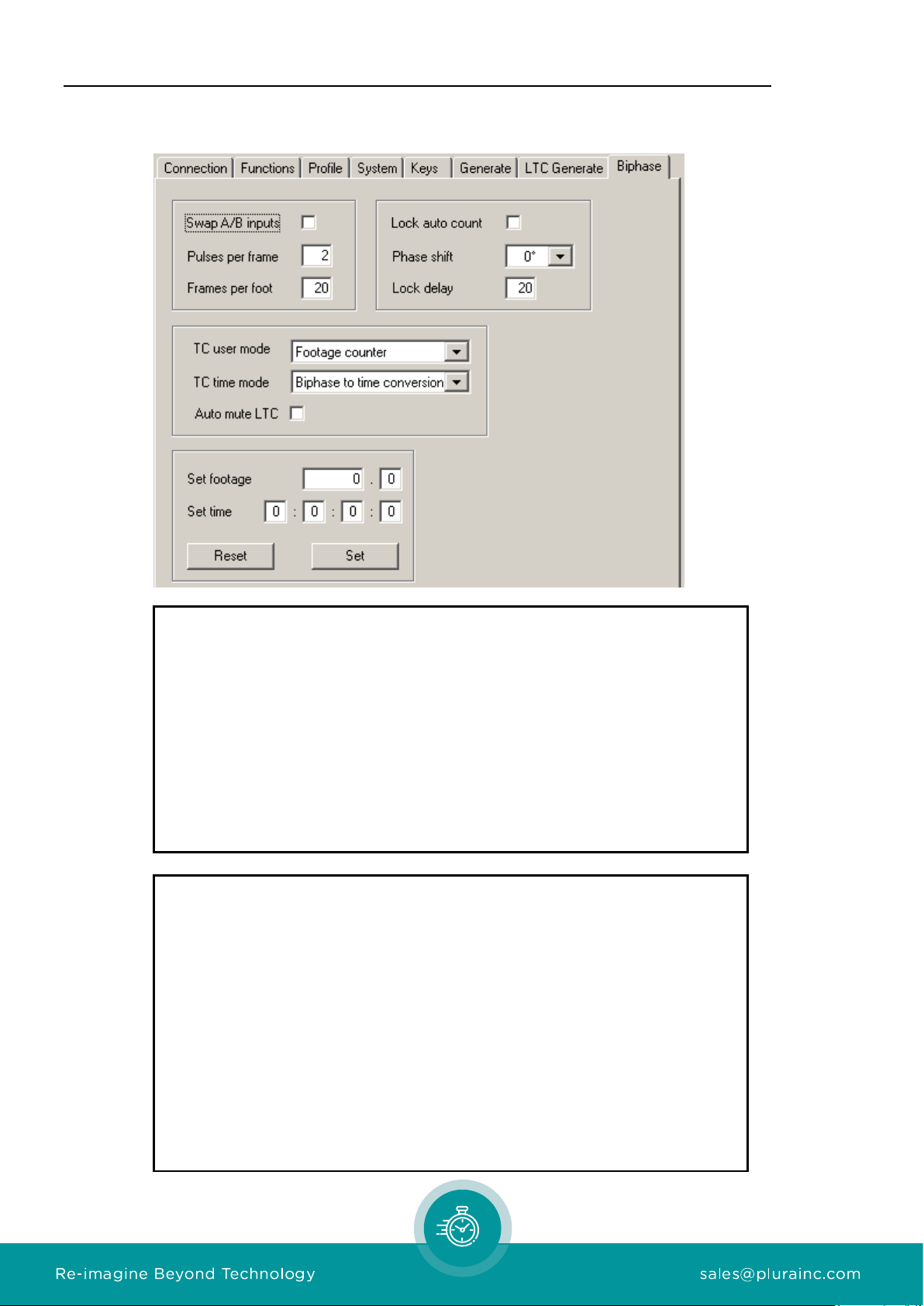
These are the key features of the system:
•Biphase pulses with 1 to 255 pulses per frame.
•Film frame counter: ± 0 to ± 99 999 999.
•Film frame rate selectable 10 to 100 frames per foot.
•Film footage counter: ± 0 to ± 999 999·99. A start value can be set.
•Biphase to time converter. A start value can be set.
•Start values can be programmed utilizing any of our configuration tools. The values can be
set pressing a front button or using a GPI input (SET and RESET function).
•Time code frame rate selectable: 24/25/30/30drop.
•The module generates LTC and/or VITC (as well as D-VITC, ATC - depending on the type
of the module). The time code generator can be genlocked to biphase, to video, to
external LTC or to internal crystal.
•The time information of the time code can contain the film frame counter (biphase to time
conversion) or a free-running counter.
•The binary groups (user bits) of the time code can contain the film frame counter, the film
footage counter, the time converted from the biphase, or a fixed programmed value.
•The film frame counter, the film footage counter and the time converted from the biphase
can visibly be inserted on a video monitor. The video windows can be positioned over the
entire screen. Size, brightness, background mask, … , can be adjusted.

Page 6 Option “P” Biphase to Time Code Converter
1.2 Configuring the RUBIDIUM Module
Upon delivery the RUBIDIUM module has got a setup to a basic configuration. The following
guide describes the most important setups and enables you to find the configuration for your
special environment. This example shows screen shots of the PC program tabs configuring an
AT module.
1. “Factory Settings”: Start the configuration after a “Reset” of the module.
Activate the “Profile” page and select: Profile: Factory Settings
Click on the OK button.
2. Select Functions:
If the “Factory Settings” has been applied the following functions now are
activated/deactivated:
To enable further functions, click on the applicable Edit and/or Use check boxes.

Option “P” Biphase to Time Code Converter Page 7
3. Basic set-up of the time code generator:
The following adjustment will be important for a biphase to time conversion:
Frame Rate: Select the frame rate of the time code: 24/25/30df/30. For a frame
accurate biphase to time code conversion this frame rate has to
correspond to the number of film frames per second. 30df
corresponds to 29.97 Hz.
Sync: Select the genlock source:
Internal internal crystal
Video at VIDEO IN connected video signal
LTC Read at LTC_IN_A / LTC_IN_B connected LTC
Biphase at GPI_1 / GPI_2 connected biphase signal

Page 8 Option “P” Biphase to Time Code Converter
4. Biphase and film parameter:
Swap A/B inputs: In case that all counters (time, footage counter, frame
counter) are counting in the wrong direction, the input
signals A and B (“R” and “S”) probably have been reversed.
Instead of changing the connection you can swap A with B
(“R” with “S”) activating this check box.
Pulses per Frame: Number of biphase pulses each film frame.
Range: 1 –255.
Example: Choice = “2”corresponds to a nominal
frequency of 50 Hz/25 fps or 60 Hz/30 fps respectively.
Frames per Foot: Number of film frames per foot. Range: 10 –100. This
enables to calculate the film length.
Lock auto count: As soon as the unit detects nominal biphase frequency (film
frame = time code frame), a “Lock” state will be indicated.
Having this check box activated the counting of time,
footage, and frames will be done automatically during
“Lock” state. This guaranties a “clean” time code output
with a continuous ±1 counting without drop-outs or jumps,
even if the biphase input signal jitters.
Lock Delay: Number of frames needed to enter the “Lock” state. Range:
10 –100.
For further details to these items please refer to chapter “Biphase to LTC
Conversion for Synchronizing Purposes”.
Phase shift: Select between: 0°, 90°, 180°, and 270°.
As default, the LTC frame is synchronized to the leading

Option “P” Biphase to Time Code Converter Page 9
edge of signal at GPI 1 (signal A or R); this corresponds to
0°. Any change to 90°, 180°, or 270° will shift the LTC
frame as shown in the diagram:
LTC: 0°
LTC: 90°
LTC: 180°
LTC: 270°
GPI1:A(R)
GPI2: B (S)
This entry mainly is relevant where “Pulses per Frame = 1”
has been selected.
TC user mode: Select the data content of the binary groups (user bits) of
the time code from the drop-down list:
No counter: Binary groups contain a fixed programmed
value (‘Set User’, refer to the “Generate“ function).
Frame counter: Binary groups contain the 8-digits film
frame counter (BCD), without sign.
Footage counter: Binary groups contain the BCD 6-digits
footage counter and 2-digits frame counter (film length),
without sign.
Biphase to time conversion: Binary groups contain the
time converted from the biphase, in a HH:MM:SS:FF
format.
TC time mode: Select the data content of the time information of the time
code from the drop-down list:
Free running: Time generated independently from the
biphase. A start value can be set (‘Set Time’, refer to the
“Generate“ function).
Biphase to time conversion: The time information
contains the time converted from the biphase, in a
HH:MM:SS:FF format.
Auto mute LTC: If this check box is activated the LTC output will be switched
off if the biphase stops. Valid only if “TC time mode =
Biphase to time conversion“ has been selected.
Utilizing the RUBIDIUM CONFIGURATION PC program, you enter a number
pressing the tabulator key at the PC’s keyboard afterwards.
Set footage: Start value for the footage counter.

Page 10 Option “P” Biphase to Time Code Converter
Range: 0.0 –999 999.99. Please stop the biphase before
setting a start value. Click on the Set button to transfer the
start value to the module.
Set time: Start value for the time converted from the biphase.
Please stop the biphase before setting a start value. Click
on the Set button to transfer the start value to the module.
Set: A click on this button transfers the current start values (‘Set
footage’ and ‘Set time’) to the module. This resets the film
frame counter to zero. This function is available for any of
the module’s function keys or for GPI_3 or GPI_4.
Reset: A click on this button resets all counters in the module: film
frame counter, footage counter and the time converted
from the biphase. This function is available for any of the
module’s function keys or for GPI_3 or GPI_4.

Option “P” Biphase to Time Code Converter Page 11
5. Adjust the video windows:
The video window can be adjusted according to your needs.
You may find the following windows suitable for your “film and time code”
application. Please notice the ‘Source’ and ‘Format’ selection.
Displaying the time of the time code (the time converted from the biphase). For
example, as “Window 1“:
Displaying the footage counter. For example, as “Window 2“:
Displaying the film frame counter. For example, as “Window 3“:

Page 12 Option “P” Biphase to Time Code Converter
6. Keys, LEDs and GPI:
The following functions for the keys are provided for a “film and time code”
application:
Biphase Reset: Resets all counters in the module: film frame counter, footage
counter and the time converted from the biphase.
Biphase Set: Transfers the current start values (‘Set footage’ and ‘Set time’)
to the module. This resets the film frame counter to zero.
These functions are available for GPI_3 or GPI_4 as well. Select from the drop-
down list.
The following functions for the LEDs are provided for a “film and time code”
application:
Gen Sync Status Indicates the state of biphase synchronisation (if ‘Sync =
Biphase’ has been selected, refer to the “Generate“ function):
LED lights up = genlock.
LED flashes slowly = fine trim procedure.
LED flashes fast = synchronization is lost.
Biphase Lock LED lights up during the “Lock“ state.
Biphase Signal LED lights up as long as any biphase signal is present.

Option “P” Biphase to Time Code Converter Page 13
1.3 Specification
The following technical data supplement or replace data presented in the manual “Functional
Description & Specifications” of the appropriate module (AT, DT, HT or XT):
GPI:
GPI_1 ... GPI_4:
Input specification
Input “Low“: -2.0 to +1.0 V
Input “High“: +3.0 to +24.0 V
Impedance: 4.7 kΩ
Frequency: 0 –1 MHz
Biphase Synchronisation:
Frequency range of the frame pulse signal
(= biphase frequency / pulses pro frame)
to obtain a phase lock of the time code.
Nominal time code frequency ± 1,5 %
at frame rate 24: 23,6 –24,4 Hz
at frame rate 25: 24,6 –25,4 Hz
at frame rate 30: 29,4 –30,6 Hz

Page 14 Option “P” Biphase to Time Code Converter
2 Connections
2.1 GPI: Input for Biphase and for Reset/Set Control
At the rear of the RUBIDIUM module you will find the 9-pins DSUB female GPI/LTC IN. Two
inputs have been reserved for the biphase signals; two inputs may be used for external push
buttons:
GPI_1
Biphase Signal A (“R”)
GPI_2
Biphase Signal B (“S”)
GPI_3
programmable, e.g. as RESET (‘Biphase Reset’ function)
GPI_4
programmable, e.g. as SET (‘Biphase Set’ function)
The switching characteristic for the RESET and SET inputs is equal to a push button, so a short
impulse (short circuit to GND) will give a trigger.
RUB
AT/DT/HT/XT
DSUB9
1: GPI_1
2: GPI_2
3: GPI_3
4: GPI_4
5: GND
1
1
GPI
SERIAL
RESET
SET
BIPHASE "A" ("R")
BIPHASE "B" ("S")

Option “P” Biphase to Time Code Converter Page 15
3 Applications
In all applications it is necessary to correctly select the parameters:
Pulses per frame,
Frames per foot.
Further it is assumed that time code and film run 1:1, i.e. film frame frequency during PLAY
corresponds to the time code frequency.
3.1 Biphase to LTC Conversion for Synchronizing
Purposes
This application requires a “clean” LTC. The time code output - synchronized to the biphase -
should be continuous without drop-outs or jumps.
With a stable biphase signal no problems are to expect. Please verify that the module accepts
the biphase signal for synchronisation doing the following simple test:
Select the basic setup:
Sync = Biphase refer to the “Generate“ function,
TC time mode = Biphase to time conversion refer to the “Biphase“ function,
LED SIGNAL = Gen Sync Status refer to the “Keys“ function,
LED SET = Biphase lOCK refer to the “Keys“ function.
With biphase at nominal frequency the LEDs SIGNAL and SET must light up –after a
run-up time of a few seconds. Once light up there should be no flashing in between!
If this test has been passed the biphase seems to have no disturbing jitter. In this case it is
recommended to work with Sync = Biphase. The ‘Lock auto count’ check box can be
activated or deactivated.
If this test fails the biphase seems to have a disturbing jitter, no long-term synchronization can
be achieved. In this case it is recommended to try out the following operating modes and to
compare the results:
Sync = Biphase and Lock auto count activated.
Sync = Biphase and Lock auto count deactivated.
Sync = Video (if present) or Sync = Internal.Lock auto count activated.
The Lock auto count mode works as follows: as soon as the unit detects nominal biphase
frequency (frequency of the film frames = frequency of the time code frames), the generator
enters the “Lock” state – after a programmable delay (Lock Delay). Now the time code
generator counts all the counters (time, footage counter, frame counter) independent. This
guaranties a “clean” time code output, with a continuous +/- 1 counting without drop-outs or
jumps. Small deviations from the nominal frequency of the biphase will not terminate the
“Lock” state, but a stop or a fast forward or reverse frequency will do. Having the time code
not phase-locked to the biphase and after a long period it is possible that a difference is built
up between the count values and the real film frames. Returning to the normal mode (“Lock”

Page 16 Option “P” Biphase to Time Code Converter
state off) all counters will get an update, if there has been any difference before now the count
values will match with the real film frames.
Having Lock auto count activated the ‘Lock Delay’ parameter has to be noticed. This value
represents a time period (in units of time code frames) during which the system should reach a
stable state (Stop →Play run-up time). A small value leads to entering the “Lock” state early.
If the film transport runs not stable at that point and the module works in the ‚Lock auto count’
mode already there is a risk to immediately have all counters not in coincidence with the real
film frames.
Selecting ‘Lock delay’ to 100 (= maximum value), the delay time equals for example to four
seconds (frame rate = 25). Only in case that the genlock source is the biphase signal (Sync =
Biphase) the “Lock” state will additionally be delayed until the phase locked has been
achieved. The ‘Lock delay’ parameter delays the termination of the “Lock” state as well.

Option “P” Biphase to Time Code Converter Page 17
3.2 Time, Footage Counter and Frame Counter in a
Time Code Format
In an application where external time code readers (time code displays) are used to visualise
the counters (time converted from the biphase, footage counter, frame counter), it is recom-
mended to deactivate the Lock auto count mode. The module can output LTC and video time
code formats –dependent on the type of module.
The data content of the time information of the time code can be the time converted from the
biphase pulses (film duration):
TC time mode = Biphase to time conversion (refer to the “Biphase“ function).
The data content of the binary groups (user bits) of the time code can be the time converted
from the biphase pulses (film duration):
TC user mode = Biphase to time conversion,
or the footage counter (film length):
TC user mode = Footage counter,
or the film frame counter:
TC user mode = Frame counter.
3.3 Time, Footage Counter and Frame Counter Visibly
Inserted on a Video Monitor
The film frame counter, the film footage counter and the time converted from the biphase can
visibly be inserted on a video monitor. Utilize the “Insert” function of one of the configuration
tools to adjust as follows:
Source
Format
Representation
Time converted
from the biphase
Generate
Time, HH:MM:SS:FF
Example:
15:56:59:13
Footage counter
Biphase Footage
Biphase Footage
6-digits footage and 2-digits
frames, with sign:
+123456.12
Film frame counter
Biphase Counter
Biphase Counter
8-digits with sign:
+12345678

Page 18 Option “P” Biphase to Time Code Converter
3.4 Two Projectors Connected via a Switching Box
The “Plura BIPHASE SWITCHER” box enables to connect two biphase sources (film projectors).
The box automatically detects the source and feeds these signals to the RUBIDIUM module,
which still counts the pulses from one projector only. During switching one count pulse will be
lost, so a “Reset” should be done if a switching has been occurred.
The connected RUBIDIUM module supplies this box with power. There is a latching relay in the
box which remains in its last position during power-off, so immediately after power-on the
signals will be passed same way as before.
The green LEDs “Select” indicate whether the signals at IN1 or at IN2 will be passed to the
OUT connector. Only one green LED lights up.
The red LEDs “Signal” indicate that pulses are present and passed to the OUT connector. One
or none of these red LEDs will light up.
RUB
AT/DT/HT/XT
+ Option P
1
1
GPI
SERIAL
Projector 1
Projector 2
1
IN1
1
IN2
1
OUT
BIPHASE SWITCHER
- - Signal - -
- - Select - -
12
DSUB9 1:1
PinAssignment IN1/IN2
DSUB9 female
1: BiphaseA("R")
2: Biphase B ("S")
5: GND
PinAssignment OUT
DSUB9 male
1: BiphaseA("R")
2: Biphase B ("S")
5: GND
6: DCIN
Specifications:
Operating voltage
12 - 30 VDC
Power consumption
Max. 0.5 W
Weight
≈ 440 g
Dimensions
103 (B) x 42 (H) x 172 (T) mm; 4.06 (B) x 1.65 (H) x 6.77 (T) inch
Material of housing
Aluminium

Other manuals for RUBIDIUM Series
7
This manual suits for next models
2
Table of contents
Other Plura Media Converter manuals