PMT AS7.M100.001 User manual

User Guide
www.precisionmounts.com
Description
Part Number
PMT Motion Manager
AS7.M100.001
1 Foot USB Cable A
-Mini B
USB2HABM1FT
Patent Pending
V2.0_04/2016 for software 1v304 and higher

Description
Motion Manager is a distracted driving solution that limits the functionality
of mobile computers while the vehicle is moving. Motion Manager helps to
prevent distracted driving to:
•comply with legislation and corporate safety policies
•reduce risk
•minimize organization liability
•provide a safer workplace
Motion Manager is a microcontroller-based peripheral that incorporates
sensor technology to detect vehicle motion. When connected, via a USB
port, to a Microsoft Windows computer with Motion Manager software
Motion Manager system can be set-up to blank the display when the
sensed vehicle motion is above the configured threshold.
The Motion Manager system consists of:
•Sensor hardware
•Detects vehicle motion
•USB A to Mini B cable
•Connects the Sensor Hardware to the computer / docking station
•Proprietary Software
•Resides on the Windows computer
•Communicates with the Sensor Hardware

Mini USB Port
Rugged Aluminum Case
LED Status Indicator Light
Mounting Plate
with holes (x2)
Dimensions
1.20” x 1.00” x 0.50 excluding mounting plate
2.10” x 1.00” x 0.50 including mounting plate
Mounting Manager Hardware Sensor
Parts and Layout

Motion Manager Features Overview
Basic function
Detects vehicle motion and blanks screen
Product Description
Microcontroller
-based peripheral with integrated motion
sensor, USB cable
System requirements
•
Operating system: MS Windows XP (SP3), Vista, 7 , 8
or 10
•
USB port
Data Logging
Administrator configurable:
•
Exports to CSV file
Mounting
Compact, robust aluminum case with mounting holes
Usage / working
environment
Unit
can be configured based on variety of driving
situations; has fast screen refresh
Key Features
In Motion Options
•
Blank display
•
Viewable display with disabled user inputs (note: user must
have administrator rights)
Screen Activation Options
•User interaction: Prevents screen from becoming active
when stopped temporarily
•
Screen automatically refreshes on stop after set time
threshold
Undocked
Computer Options
•
Computer functions as normal
•
Blanks display

Operation
•Once the administrator completes the installation and configurations
the operation of Motion Manager requires no user interaction for start
up.
•The Motion Manager Sensor Hardware can remain connected to a USB
port on the dock at all times or it can be connected when required.
•The Motion Manager Sensor Hardware will start automatically as soon
as it becomes receives power.
•When properly installed in the Start-up menu of the computer, the
Motion Manager software will automatically start when the computer
is started.
•When the software detects the hardware a connection is automatically
established and the Motion Manager system will function.
•The Motion Manager Sensor Hardware is equipped with a LED status
indicator light:
•Blinking green: Motion sensed is below the configured threshold
•Blinking red: Motion sensed is above the configured threshold

Installation
1) Software
•Sign on to the computer under a user with Administrator credentials.
•Locate the exe file “BlackWhiteController1vXXX.exe” provided by PMT
or your equipment provider (possibly in a zip file that will need to be
extracted before proceeding.
•In the Program Files (x86) folder
•Create a “PMT” folder and in that folder create a “BWC” folder
•Place the exe file in the “BWC” folder
•Place a shortcut to the exe file into the Startup folder of the Windows
Start menu.
•Under Win7
•Click on the Start button
•Right-click on the All Programs item and select “Open All
Users”
•Double-click on the Programs Folder
•Double-click on the Start up Folder
•Place a shortcut to the application in the Start-up folder
•Give the program the ability to run as an administrator for
all users by right clicking on the shortcut and using
Properties -> Compatibility -> Change settings for all users
•Under Windows XP the procedure is similar
•Under Windows 8 and 10 locate the user Startup folder and
place a shortcut to the exe file

Installation
2) Drivers
•In order for Motion Manager to communicate with the computer you
will need a driver for the UART communication port to the Motion
Manager Sensor Hardware.
•In most cases the computer will automatically download the driver.
•Ensure that the computer has Internet connectivity before connecting
the Motion Manager Sensor Hardware
•Connect the Motion Manager Sensor Hardware
•Plug the Motion Manager Sensor Hardware into a USB port on
the computer OR dock the computer in a dock equipped with the
Motion Manager Sensor Hardware
•After the driver has finished loading, restart the computer. This will
properly start the PMT Motion Manager Controller.
•If your computer doesn’t download the driver automatically, the driver
is also provided by PMT in 32 bit and 64 bit or it can be manually
downloaded at http://www.ftdichip.com/Drivers/VCP.htm

Installation
3) Sensor Hardware
Note: If you have purchased a PMT vehicle dock that has been integrated
with Motion Manager then skip this step.
•Select a position on the vehicle that will allow the Motion Manager
Sensor Hardware to sense motion of the vehicle. Positions where the
Motion Manager will sense movement of the operator should be
avoided.
•The Motion Manager Sensor Hardware may be screwed down or fixed
into position with industrial strength double sided tape or Velcro. For
best results ensure that the Motion Manager Sensor Hardware is not
mounted to anything that will absorb vibrations . A good solid mount
to something connected to the chassis is recommended.
•The orientation of the Motion Manager Sensor Hardware is not
important. Orient the Motion Manager Sensor Hardware to make
cable placement efficient.
•Connect the sensor to one of the dock’s USB Ports.
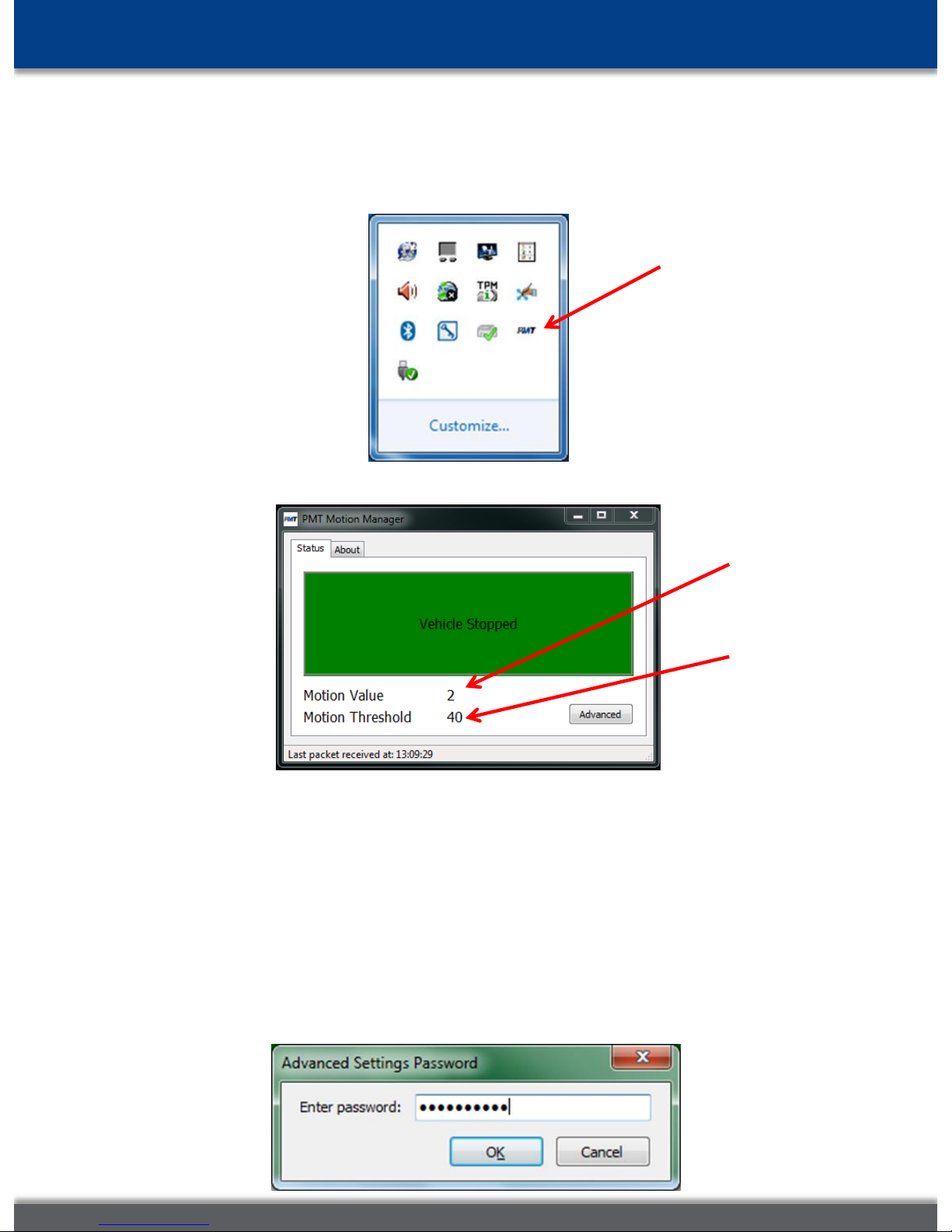
4) Configuration
•When first installed, you will need to configure the sensor through the
Motion Manager software. Complete configuration instructions are
included with this User Guide
•After applying the completed configuration, close the configuration
window and minimize the status window. The system will save the
settings to a file on that computer. Each time the system starts it will
recall the last saved configuration.
•If you change computers you will have to install the software and set
the configurations again.

Configuration
•Open the System Tray and double click on the PMT icon.
•Double clicking the PMT icon will open the status window.
•The status window will show one of the following
•Vehicle Stopped
•Vehicle Moving
•Waiting to search
•Hunting
•Configuring
•Click the advanced button and enter the password “MMAdmin14”
•Click OK
Current detected
motion
Current motion
threshold

Configuration Continued
•This will open the PMT Motion Manager Settings window
•As a starting point, set values to match those shown above
•Note: Communications Port value can be different based on the
system that Motion Manager is connected to.

Configuration Tab Definitions & Settings
•Communications: Port
•The Motion Manager software is programmed to automatically
detect the USB port in use with the Motion Manager Sensor
Hardware. User setting is usually not required.
•USB serial port can be located using the device manager. It will
be the last entry in the Ports (Com & LPT) list.
•Each time the computer starts up it will search for the device and
download the last configuration when found. (Note: On the first
start-up after the controller software is installed it will download
the default configuration)
•Communications: Status Rate
•The time between communications from the sensor to the
computer. The sensor collects data at 400Hz and processes it to
determine the motion status, but only updates the motion
status to the computer as often as set by the status rate setting.
•The units for the number in this field is X*10 milliseconds
•1 equals 10 milliseconds equals 1/10 second
•50 equals 500 milliseconds equals ½ second
•100 equals 1000 milliseconds equals 1 second
•Setting the update rate to a long period will increase the time
required for the screen to turn on after a stop as it waits for the
sensor to send the current status. With a long setting it is
possible to miss a very short stop which is very desirable. (Note:
The duration settings are also designed to limit false starts and
stops)
•Communications: Speed
•User setting not required.
•Leave at 38400

Configuration Tab Definitions & Settings
•Detection Parameters: Motion Threshold
•The amount of sensor movement that is considered to be vehicle
motion.
•Higher values require more vehicle motion to trigger the screen
shut down.
•Detection Parameters: Exp Period
•The amount of smoothing of the sensor signal. Higher values
create a smoother signal.
•For most applications we recommend 7 for this value.
(smoothing over ~1/3 sec)
•Detection Parameters: Trigger Duration & Clear Duration
•Trigger and clear duration settings are used to limit false signals
by requiring a number of samples to be above or below the
threshold value.
•The Trigger Duration value sets the number of data samples
required to be above the threshold before blanking the display.
•The Clear Duration value sets the number of data samples
required to be below threshold before turning on the display.
•Detection Parameters: Scale Factors
•User setting not required.
•Leave at 256

Configuration Tab Definitions & Settings
•Actions: On Motion
•Sets what happens once motion threshold is exceeded
•Options are:
•No action
•Nothing happens and computer functions are
normal
•Blank Display
•Screen goes blank (black)
•Block Input
•Display remains viewable and user input is disabled
•Actions: No Sensor
•Sets what happens when the sensor hardware is not detected
(sensor unplugged or computer undocked)
•Options are:
•No action
•Nothing happens and computer functions are
normal
•Blank Display
•Screen goes blank (black)
•Actions: Restore screen when stopped
•When this box is checked the screen will automatically reactivate
from blank (black) once the vehicle is stopped (recommended for
forklift applications)
•When this box is unchecked the user has to manually reactivate
the screen by pressing a key on the keyboard, touching a touch
screen or touching a touch pad (recommended for automobile
applications)
•Actions: Test “On Motion” Option
•By pressing this button the system will simulate exceeding the
motion threshold and display the configured actions

Configuration Tab Definitions & Settings
•PMT Banner
•Use this option to display and position a banner that reads
•“PMT Motion Manager Active”
•The banner will help to inform the user that the Motion Manager
is active and is particularly useful when the action is set to Block
Input
•Change Password
•Change password from default
•Apply
•When making changes to the settings always press Apply before
Close

Status Tab Definitions & Settings
•Section 1 shows transmitted data status and the firmware version.
•Section 2 shows the active configuration settings
•Section 3 shows the actual data being measured by the sensor
•Section 4 check box sends measurement data to the log page
1
2
3
4

Log Tab Definitions & Settings
•By default this tab shows a running log of actions and status
•To add data to the log
•Check the “Enable logging of status packets” box on the Status tab
•The log automatically starts when the computer starts and is erased when
the computer is powered down.
•The Log to File function allows the log to be automatically saved to a file
making the data available for future review
•This function can be used to determine if and when the Motion Manager
has been disconnected from the computer
•Browse to set the file location and check the “Enabled” box
•The data file can be saved to a local file or mapped network file
Table of contents
Other PMT Automobile Accessories manuals
Popular Automobile Accessories manuals by other brands

Alpine
Alpine i509-WRA-JK installation manual

Big Country
Big Country 372901 installation instructions

Flash Cover
Flash Cover MN012 installation manual

Westfalia
Westfalia 305 407 300 107 Installation and operating instructions

Holley
Holley Terminator Stealth EFI installation manual

Menabo
Menabo JUZA Fitting instructions

Muncie
Muncie OMNI-SYSTEM PLUS OPERATION AND CONFIGURATION MANUAL

Polaris
Polaris 2879373 quick start guide

Circutor
Circutor Wallbox eNext Series installation guide

Westin
Westin 27-1585 instructions

Western
Western 96500 WIDE-OUT operating instructions

Kuda-Phonebase
Kuda-Phonebase 084400 Installation instruction