JT Innovations Toucan User manual

Page
1
Toucan Touchscreen Gauge and CAL Selection Unit
User Guide (Generic) V1.96A
For Toucan Firmware Version 1.96 and above, all ECUs
Disclaimer
support@JTi.uk.com
www.JTi.uk.com
+44 (0) 1305 534535
© JT Innovations Ltd. 2022
Disclaimer
Although every care is taken with the design of this product, JT Innovations Ltd. can in no
way be held responsible for any consequential damage resulting from the use of Toucan in
your vehicle.
Always operate your vehicle safely and do not allow yourself to be distracted by your
Toucan display while driving. Minimise the amount of time you spend viewing the screen.
Do not access any function requiring prolonged use of the menus whilst driving.

Page
2
Contents
Introduction............................................ 2
Installation.............................................. 2
Before You Start ................................. 2
Installation.......................................... 3
Connectors...................................... 3
Power.............................................. 3
CAL Switch –Grey Wire .................. 4
Data Connector............................... 4
Multiway Connector ....................... 4
In-vehicle Mounting........................ 5
Initial Toucan Configuration ............... 5
CAL switch configuration ................ 5
Doesn’t work?................................. 6
Datastream Configuration ...................... 7
Link (and Vi-PEC)................................. 7
Gauge Data Setup........................... 7
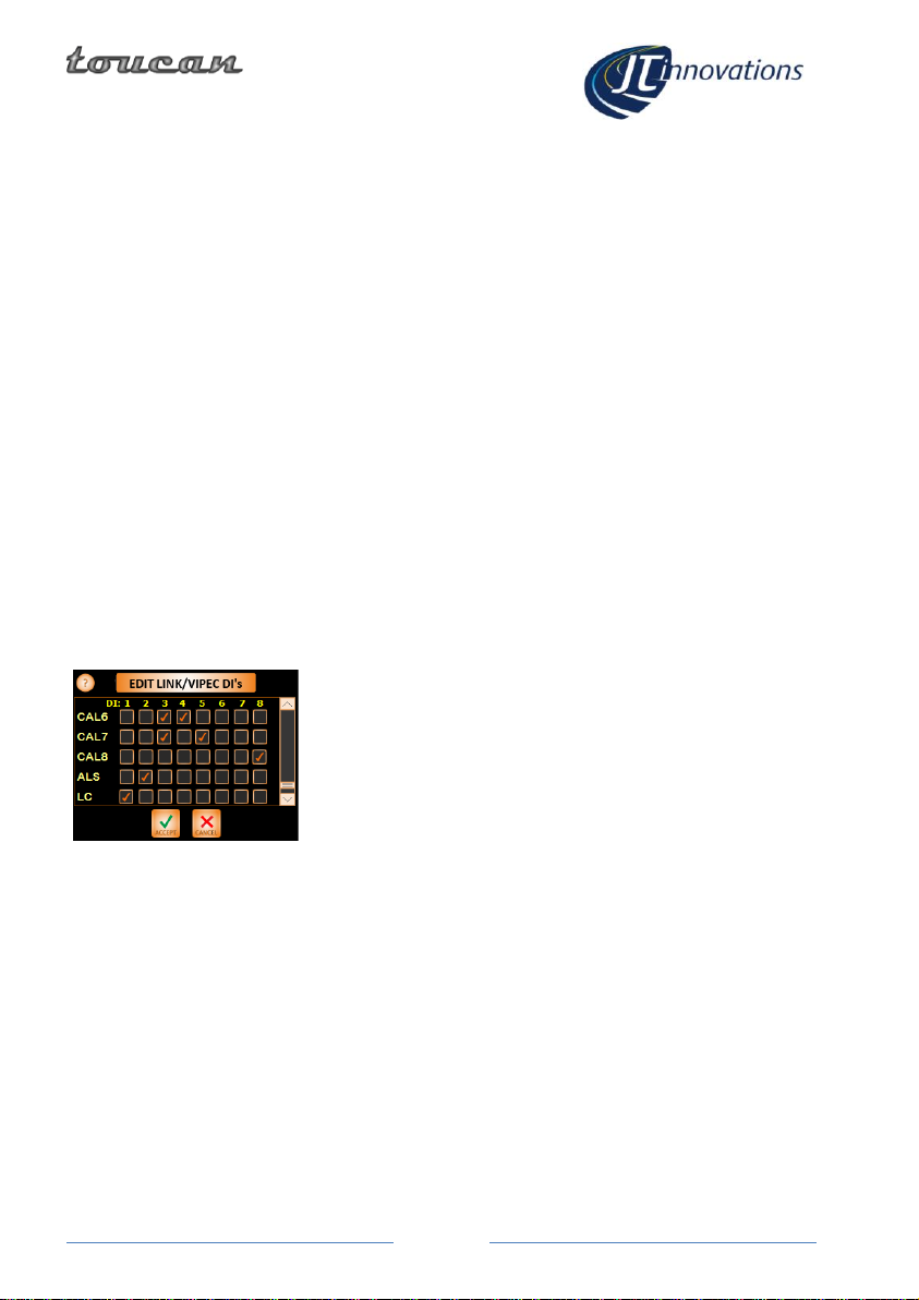
CAN DI Control Functions ............... 8
ECU Configuration –Anti-Theft ...... 8
Syvecs/Life Racing............................... 9
Toucan Receive (RX) Modes ........... 9
Toucan Transmit (TX) Modes........ 10
SCal Configuration for “Generic
Receive”, S7 using CAN2, or S8/12 10
5V Output Modes ......................... 11
Additional Features .......................... 12
Sensor Alarms............................... 12
Changing Frame/Slot Assignments
(except S7 CAN1 which is Fixed)... 12
Turning Parameters Off ................ 13
Extended Gauge Set...................... 13
Status Indicators........................... 13
Launch RPM .................................. 13
Emtron.............................................. 14
Configuring the Gauge Datastream
...................................................... 14
Haltech and ECUMaster.................... 15
Trim Switch ................................... 15
MoTeC M1 ........................................ 16
MoTeC Control Functions ............. 16
AlcaTek.............................................. 17
Simtek............................................... 17
CANbus Termination......................... 17
Menus and Operation........................... 18
Gauge Screens .................................. 18
Settings Menu................................... 19
Setup Menu ...................................... 19
Gauge Layout.................................... 20
CAL Selection Menu.......................... 20
Traction Control Selection Menu...... 20
Editing CAL Text ............................ 21
CAL Voltage Adjustment ................... 21
CAL PIN Protection............................ 22
Alarm Configuration ......................... 23
Available AlarmsError! Bookmark
not defined.
Shiftlight Configuration..................... 24
“More” Menus.................................. 25
Keypad.................................................. 26
Firmware Updates ................................ 26
Technical............................................... 27
CAN ID Ranges and Toucan Auto-detect
.............................................................. 28
Introduction
Thank you for purchasing a Toucan display. We hope it will be easy to install and configure,
and we suggest that you read this guide before installation.
Installation
Before You Start
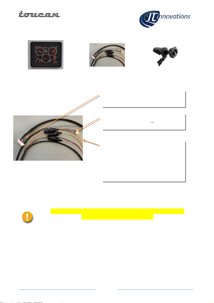
Please check the box contents to ensure nothing is missing. You should have:
Unit
Cable Harness
Mount

Page
3
Installation
Connectors
ENSURE THE CAR BATTERY IS DISCONNECTED BEFORE ATTEMPTING TO
INSTALL YOUR TOUCAN DISPLAY UNIT
IF IN DOUBT, PLEASE CONSULT A QUALIFIED AUTOMOTIVE ELECTRICIAN
Power
Each power feed has an inline fuse holder pre-fitted with a 1 Amp 20mm glass fuse.
Ensure a good ground connection is provided to the BLACK wire.
To allow Toucan to power up quickly, it is recommended that a connection to both a
permanent and switched (i.e., only live when the ignition is on) vehicle battery feeds are
made. When the ignition is off, Toucan will consume about 40 milliamps from the
BLACK Power Ground
YELLOW Permanent +12V
PINK Switched +12V
ORANGE Lighting circuit
GREY CAL Switch
Multiway Connects to Toucan
unit
5 pin ECU data connector

Page
4
permanent connection –a typical, healthy, 40 amp-hour vehicle battery will last over a
month before being run completely flat by Toucan: but it’s your choice.
If you decide not to connect the YELLOW permanent +12 Volt, please make sure it is
wired along with the PINK connection to the switched ignition feed; otherwise, Toucan
may not start up when you turn on the ignition.
Toucan will take about 6 seconds to start if the permanent +12 Volt feed is not connected
compared to less than a second when the permanent connection is made.
A connection to the vehicle lighting circuit may be made using the ORANGE connector –
this will allow the Toucan unit to automatically dim when the vehicle lights are turned on.
If not required, please insulate the unused wire to prevent damage to the unit or vehicle.
CAL Switch –Grey Wire
The long GREY wire may be connected to an ECU input for analogue (0-5V) CAL/MAP
switching if required –if not, please make sure the bare end is insulated.
-Syvecs. The grey wire may be used, connected to a 0-5V input configured as a
CAL switch but in most cases, switching will be via CANbus (see later)
-Link, AlcaTek, SimTek, ECUMaster, Emtron. Not generally used.
-Haltech –may be used if supported and required
-MoTeC M1 –some variants do not support CAN receive, so this wire can be
used if required.
Data Connector
The Toucan cable is pre-fitted with a 5-way white connector suitable for Link G4+/G4X
plugin ecus. If other ECUs are used this connector can be cut off and connections made
directly to the ECU.
Cable Colour
Function
Violet
RS232 RX
Blue
RS232 TX
White
CAN HI
Green
CAN LO
If used with a Syvecs Subaru Impreza PnP model then the PnP module is fitted with an
RJ11 MODEM-style connector. An combined adapter and 1m extension cable for this is
available from us.
Multiway Connector
This connects to the rear of the Toucan unit. Note that it has a latching tab that must be
depressed before the connector and cable can be detached.
The connector is intended to allow occasional removal of the unit from the car to allow,
for example, firmware updates to be applied.

Page
5
When detaching the unit, take care not to put unnecessary strain on the
wires otherwise they may be damaged.
In-vehicle Mounting
Toucan is fitted with a mounting plate using the AMPS mounting hole pattern (common
to many phone and satnav mounting systems). The plate suits the Arkon dual-T mounting
system, and a vent mount is included. Alternatives are available online - search for “Arkon
Mount” and then look for “dual-T” compatible mounts.
Initial Toucan Configuration
Having checked the installation of your Toucan, ensuring all connectors are fully home
and especially that the power wiring is correct, reconnect the vehicle battery and turn on
the ignition. After a few seconds, Toucan should power up and display the main gauge
screen.
CAL switch configuration
If Toucan is being used to select calibrations via the grey wire rather than CANbus (see
later), it is necessary to check that the voltage thresholds configured in the ECU match
those of your Toucan. Toucan supports 8 or 12 CAL positions. Analogue rotary CAL
switches vary, and your mapper may have adjusted the ECU values to match your specific
switch. These are typical threshold values:
8 CAL POSITIONS
CAL
ECU threshold
Toucan
Voltage
1
<0.36V
0.00V
2
>0.36V, <1.07V
0.70V
3
>1.07V, < 1.68V
1.40V
4
>1.68V, < 2.19V
1.95V
5
>2.19V, <2.79V
2.50V
6
>2.79V, <3.20V
3.00V
7
>3.20V, <3.61V
3.40V
8
>3.61V
4.00V
Other manuals for Toucan
1
Table of contents
Popular Automobile Accessories manuals by other brands

ULTIMATE SPEED
ULTIMATE SPEED 279746 Assembly and Safety Advice

SSV Works
SSV Works DF-F65 manual

ULTIMATE SPEED
ULTIMATE SPEED CARBON Assembly and Safety Advice

Witter
Witter F174 Fitting instructions

WeatherTech
WeatherTech No-Drill installation instructions

TAUBENREUTHER
TAUBENREUTHER 1-336050 Installation instruction