Pneumax 140-SP User manual

PTO-Driven Compressor Kit Installation Guide
Page 1of 36
PTO-Driven Compressor Kit Installation Guide
Applies to the Pneumax models
140-SP
200-SP
FOR INSTALLATION CENTER USAGE ONLY
Pneumax, Inc.
8557 North 78th Ave.
Peoria, Arizona 85345
623-979-3398
Fax: 623-979-6949
www.pneumaxcafs.com

Pneumax PTO-Driven Compressor Kit Installation Guide
Page 2of 36
Table of Contents
Installation Overview.........................................................................................................................4
Power take-off suggestions ...............................................................................................................5
PTO installation.................................................................................................................................6
Air compressor installation.................................................................................................................7
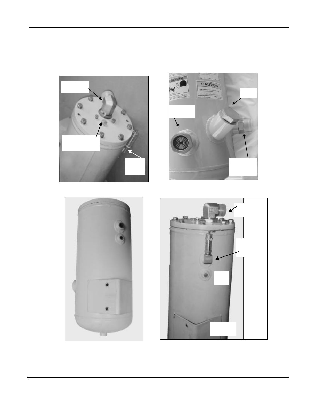
Air-oil sump installation......................................................................................................................8
Oil Temperature Gauge (all sumps).................................................................................................11
Separator/filter installation............................................................................................................... 12
Air Compressor Cooler and Hydraulic Filter Installation....................................................................13
Auto-Sync....................................................................................................................................... 15
1. UNLOAD Mode Adjustment.....................................................................................15
2. FIXED Mode Adjustment .........................................................................................16
3. AUTO Mode Adjustment..........................................................................................17
Suggested components for CAFS discharges:.................................................................................18
Discharge kits...............................................................................................................18
Air distribution manifold: ...............................................................................................18
Suggested air hose ......................................................................................................18
Air Pressure Gauge......................................................................................................18
Compressor System........................................................................................................................19
Schematics and Dimensional Drawings...........................................................................................23
Basic Compressed Air Foam System (CAFS) Schematic..............................................23
80-SP with 8-inch Vertical Sump, Hydraulic Schematic.................................................24
140/200-SP with 10-inch Vertical Sump, Hydraulic Schematic......................................25
80-SP Manual Auto-Sync Valves, Air and Water Connections.......................................26
140/200-SP Manual Auto-Sync Valves, Air and Water Connections..............................27
Compressor Installation Angles....................................................................................28
Eight-Inch Vertical Sump..............................................................................................29
Ten-Inch Vertical Sump................................................................................................30
80-P Heat Exchanger (Oil cooler).................................................................................31
140/200-SP Heat Exchanger (Oil Cooler) .....................................................................32
80-SP Separator Filter..................................................................................................33
140/200-SP Oil and Separator Filters ...........................................................................34
Balance Valve and Auto-Sync Controls, Panel Cutout...................................................35
Companion Flange.......................................................................................................36

Pneumax PTO-Driven Compressor Kit Installation Guide
Page 3of 36
Warnings, Cautions, and Notes
Warning A warning alerts you to a procedure, practice or condition that may result in death or
long-term injury to personnel or destruction of equipment.
Caution A caution alerts you to a procedure or condition that may result in serious damage to
equipment or its failure to operate as expected.
Note: A note points out important information. Failure to read the note will not result in
physical harm to personnel or equipment. It may waste time and money.
Revision History
Revision Date Issued Comments
1.0 3/1/04 Original Release
2.0 5/4/04 2nd Release

Pneumax PTO-Driven Compressor Kit Installation Guide
Page 4of 36
PNEUMAX PTO-driven Compressor Installation
Guide
Installation Overview
This guide is for installation of the compressor system. There may be some variables
depending on specific applications. Since there are many ways to which discharges can be
configured, if the application on a particular vehicle is not covered in this guideline, we will
be happy to assist with specific needs of the customer in the design of the system.
Note: Air is always injected after the water/solution valve. This will give each discharge the
best performance possible.

Pneumax PTO-Driven Compressor Kit Installation Guide
Page 5of 36
Power take-off suggestions
There are many PTO suppliers and various types of transmissions available, and the choice
of PTO will in part depend on what can be installed in the vehicle. "Hot Shift" PTOs are
commonly used.
Make sure that there will be room to install the air compressor on a bracket close to the
PTO, with their drive angles matched.
Caution: The driveline angles MUST be matched to prevent serious damage to the compressor,
PTO, or transmission.
Specific gear ratios vary among the different transmissions and PTO suppliers. The ratios
suggested below are a guide for selecting the PTO. With these ratios, the rated CFM is
usually achieved with the engine speed between 1400 to 1600 RPM.
Caution: A higher speed on the PTO means the CAFS system will reach the desired CFM at
lower engine speeds. Exceeding the compressor's rated RPM can damage the
compressor, and void the warranty. In such applications, an over speed cut-out
should be installed on the PTO to protect the compressor.
DO NOT engage PTO above 1000 Engine RPM.
To calculate the possible compressor RPM, use this equation:
Engine RPM x gear ratio on PTO x compressor gear ratio = compressor RPM
80-SP Compressor
CFM required PTO speed HP average
80 160% HI 22
80 184% HI 22
140/200-SP Compressor
CFM required PTO speed HP average
120-140 143% HI 32-40
200 160% HI 55-60
Some applications may require a PTO running faster than typical requirements, for
example:
200 187% HI 55-60

Pneumax PTO-Driven Compressor Kit Installation Guide
Page 6of 36
PTO installation
Follow the PTO manufacturer's installation guidelines.
Caution: Because the compressor is cooled by water from the water pump, we strongly
suggest that the compressor is only engaged while the water pump is engaged. This
is accomplished by using the "OK to PUMP" circuit to trigger the PTO system.
Wiring the PTO switch circuit in parallel with the "OK to Pump" light is one way to ensure
that the PTO and compressor cannot be activated unless the fire pump is engaged.
From
“OK to Pump”
“OK to
Pump”
Light
PTO
Switch
Ground To PTO

Pneumax PTO-Driven Compressor Kit Installation Guide
Page 7of 36
Air compressor installation
Compressor mounting bracket is supplied with kit. Mounting bolts of the proper size are
provided with the Compressor Kits since these are metric thread. The installer can
manufacture a mounting bracket for the Compressor if so desired.
Caution: The air compressor cannot be installed on its side. It must remain upright, with the
air intake on the top.
Once again, remember that the driveline angles on the compressor need to match the
driveline angles on the Power train.If driveline angles are not matched, this could
result in bad vibration issues that could lead to driveline failure or cause the Air
Compressor to fail.
If you have questions concerning driveline angles, please contact your driveline
supplier.
The air inlet on the Air Compressor can be turned to any direction, as the bolt pattern is
symmetrical. This way the air inlet can be turned any direction to ease installation of the air
filter.
The air filter is supplied with the kit along with a T-Bolt clamp. For basic installation, the air
inlet tubing supplied to connect the filter to the air inlet is steel tubing and rubber.
Remember it is an air inlet, just as in an engine. The easiest thing we have found is
aluminum or steel tubing thin wall. DO NOT use flexible exhaust tubing or anything water or
dirt can easily penetrate.

Pneumax PTO-Driven Compressor Kit Installation Guide
Page 8of 36
Air-oil sump installation
Note: Pneumax will not be responsible for systems where the sump and sight glass are
installed such that the oil level cannot be checked or does not display the correct oil
level due to improper installation.
The sump works best when it is installed so that the sight glass opening is at or below the
level of the Air Compressor.
In some cases, finding room for the sump can be difficult. It is acceptable to mount the oil
sump up to 12 inches higher than the air compressor; however this may require the
installation of an oil inject check valve to prevent oil from flooding the compressor. It is
usually fine, though, without this check valve. Oil inject check valve may be ordered from
Pneumax when ordering the system or can be installed after the system has been tested.
Suggested part numbers for this check valve are available through Pneumax.
The oil fill-sight glass on the Oil Sump is next to the oil fill port. It is necessary to locate the
sight glass in an accessible location for ease of checking or adding oil, usually near a door.
It is the responsibility of the installer to make sure the oil can be reasonably checked and
added if necessary.
Suggested oil to be used in the system:
•ISO 68 wt Hydraulic Low Foaming Anti-Foaming

Pneumax PTO-Driven Compressor Kit Installation Guide
Page 9of 36
80-SP Vertical Sump
The Safety Pressure Relief valve may be installed in either of the ports. The remaining ports
have no options.
Vertical sump, top view Vertical sump, side view
Out to
Separator Filter
Safety
Pressure Relief
Inlet from
Compressor
Oil Level
Sight Glass
Oil Drain
Oil out to
Filter
Oil
Fill

Pneumax PTO-Driven Compressor Kit Installation Guide
Page 10 of 36
140/200-SP Vertical Sump
The Safety Pressure Relief valve may be installed in either of the ports. The remaining ports
have no options.
From
Compressor
Safety Pressure
Relief (alternate
installation point)
Safety
Pressure
Relief
Vertical sump, top fittings Vertical sump, lower fittings
Not
Used
Mounting
Bracket
Safety
Pressure
Relief
From
Compressor
Vertical sump, rear view Vertical sump, rear view
Oil Level
Sight Glass
Oil Fill
Air/Oil
from
Compressor

Pneumax PTO-Driven Compressor Kit Installation Guide
Page 11 of 36
Oil Temperature Gauge (all sumps)
Mount the gauge on the pump operator's control panel where it will be easy to monitor.
•The gauge connects to the larger of the two prongs on
the sender.
•The smaller prong, which is labeled "WK", may be used
to activate an oil temperature warning light or alarm (not
provided). Pneumax recommends installing an over-
temperature device.
This prong is one side of a temperature sensitive switch
that will close at 250°F. The other side is grounded
through the metal of the sump.
The prong can be connected to the negative side of an
audible alarm or warning light.
•Follow the installation instructions in the temperature
gauge box to connect the sender to the gauge and the
optional warning light.
Audible
Alarm
Basic Wiring Schematic for Oil Temperature Gauge
Temperature sender, on
Sump

Pneumax PTO-Driven Compressor Kit Installation Guide
Page 12 of 36
Separator/filter installation
The separator filter can be installed anywhere there is room to securely mount it and run the
hydraulic and air lines. The only requirements are to make sure that the filter element can be
serviced reasonably and that the assembly is installed properly.
•Install it vertically, with the housing up, the filter element down.
•Make sure there is room to remove and replace the filter element.
Oil Scavenger
to Compressor
(behind bracket)
To Balance Valve and
Fixed/Manual Regulator
To Air
Manifold
From
Sump
Separator/filter side view with fittings
Oil Scavenger
to Compressor
From
Sump
Separator/filter and bracket detail

Pneumax PTO-Driven Compressor Kit Installation Guide
Page 13 of 36
Air Compressor Cooler and Hydraulic Filter Installation
Caution: Do not install a shutoff valve in the heat exchanger water supply. This will result in
system overheat and failure, and void the manufacturer’s warranty.
The oil returning to the compressor is cooled by passing it through a water-cooled heat
exchanger, usually called the cooler.
Compressor Cooler Assembly
•Hydraulic filter functions as the oil inlet. Oil outlet is the #8JIC fitting on the other end.
•Hook up incoming water line to the wye strainer. Water outlet is just to the left of the
Wye strainer. The drain is the lower 3/8” FNPT fitting.
•Install the cooler so that it can be drained to prevent freeze damage.
•The cooler must be installed horizontally (COOLER CANNOT STAND ON END),
with the drain at the lowest point, and with a slight slope toward the water drain end.
•The drain hose should be 0.500”I.D. minimum to provide proper drainage.
•The outlet of the drain hose must be lower than the cooler's drain outlet and the drain
hose should be a continuous downward run (no goosenecks) to allow proper
drainage.
To mount the cooler on the side of a compartment, unbolt the brackets from the ends
and reattach them so the cooler can be installed with the drain at the lowest point.
# 8 JIC
Fitting
Hydraulic
Filter Wye Strainer
Drain
3/8” FNPT

Pneumax PTO-Driven Compressor Kit Installation Guide
Page 14 of 36
Connecting the cooler water lines and wye-strainer
The cooler water is supplied by diverting water through the wye-strainer supplied by
Pneumax from the discharge side of the fire pump (see the Hydraulic Schematic). The
cooling water supply hose should be 0.5”to 0.625 I.D. for the 140/200-SP to supply the
proper flow for cooling the system. The cooler discharge water may be routed back to the
booster tank fill tower or returned to the inlet side of the pump.
Normally, coolant water is returned to the booster tank and a check valve is installed in-line
to prevent backflow from the tank through the cooler and so as not to interrupt drafting
operations (A ½” check valve is supplied with the kit). However, during drafting and hydrant-
supplied operations, the booster tank may overflow because of the cooler water return. If
this is objectionable, route the return line to the inlet side of the pump. In this case, it is not
necessary to install an in-line check valve, but it will be necessary for the pump operator to
open the tank fill valve during operation to prevent overheating the fire pump.
Wye Strainer for Cooler
A wye-strainer is installed to strain water before it enters the cooler's water supply inlet. The
wye strainer is a service item and should be in an accessible location for service and/or
cleaning.
Caution: Pneumax is not responsible for damage due to plugged strainers. If the customer’s
water system contains excessive debris, or the vehicle relies on drafting for its water
supply, it may be necessary to install a larger strainer and/or a clean-out valve on the
wye-strainer.
Without good water flow through the heat exchanger, the compressor will overheat.
Compressor performance will be inadequate, and it may fail completely.
Omitting the Wye-strainer or removing the screen from the Wye does not improve
water flow. It will allow debris into the cooler, which can clog the tiny heat exchanger
tubes and restrict water flow.
Hydraulic Filter Installation
Caution: This is a one-way filter. Oil must flow in the direction indicated by the arrows on the
top of the filter.
The hydraulic filter should be mounted to the compressor cooler. This eliminates the need to
find a mounting location and simplifies the system hosing. It is best to keep the hydraulic
hose runs as short as possible, especially for the #8 lines from the sump to the filter/cooler
and to the oil inject at the compressor.
•Make sure there is enough room so the filter can be removed and replaced.
•Make sure the direction of oil flow is correct.

Pneumax PTO-Driven Compressor Kit Installation Guide
Page 15 of 36
Installation and Adjustment of the Auto-Sync Air
Balancing System
Colored hoses and fittings are supplied with the compressor kit for the average installation.
The schematic is color coded to simplify installation. This also makes future service issues
easier to resolve, provided suggested hose colors are used.
CAFS retrofit kits and any other system shipped as separate components will need
calibrating after installation.
Note: Before you make any adjustments, make sure the oil level in the sump is correct, and
the air lines do not have leaks or obstructions. Do not adjust the Auto-Sync
components to compensate for problems elsewhere in the CAF system.
Always start by adjusting UNLOAD mode, then FIXED, then AUTO.
Auto-Sync
1. UNLOAD Mode Adjustment
1. Set the controls on the Auto-Sync control panel to FIXED and UNLOAD. (UNLOAD for
electric valves)
Manual Valve Control
2. Close all air discharges.
3. Locate the Air Inlet Trim Valve, near the air inlet on the compressor.
Air Inlet
Trim Valve
Fixed/Manual Pressure
Regulator
Compressor adjustment points

Pneumax PTO-Driven Compressor Kit Installation Guide
Page 16 of 36
4. Turn the valve clockwise until it is completely closed, then open it three full turns.
5. Locate the Piloted Balance Valve (PBTV), and turn the needle valve counterclockwise to
full open.
PBT
Valve
Piloted Balance Trim Valve (PBTV)
6. Start the fire pump, and with the engine at idle, establish water flow through a discharge
or tank recirculation.
7. Engage the PTO.
Caution: Do not engage the PTO above 1000 engine RPM.
8. With 140/200-SP systems, the main pressure gauge should read approximately 40 PSI
with all discharges closed. Some systems may read lower. This is acceptable.
2. FIXED Mode Adjustment
The usual pressure for a newly installed PTO retrofit kit is about 110 PSI. It must be
adjusted to 150 PSI.
1. Locate the Fixed/Manual Pressure Regulator on the compressor and loosen the lock nut
on the adjustment screw.
2. Place the controls on the Auto-Sync control panel to FIXED and RUN. Wait until the
compressor pressure stabilizes.
3. The target operating pressure is 145-150 PSI. Monitor the air pressure reading as you
adjust the regulator screw. Give the system several seconds to stabilize between
adjustments, and make partial turns of the screw to avoid overshooting the target
pressure.
•Turning the screw IN (CW) will increase pressure.
•Turning the screw OUT (CCW) will decrease pressure.
4. After the desired fixed pressure is achieved, tighten the lock nut.
5. Verify that the fixed regulator is performing properly by varying the engine speed as you
watch the air pressure gauge. The pressure should remain steady at the setting you
made. Repeat steps 2 through 7 of previous step if needed.
Turn the control to UNLOAD and back to RUN (To UNLOAD and back to FIXED for
electric valves). The air pressure should rise to the fixed pressure. It may overshoot
and drop back to the target pressure, but that is normal.
After the FIXED mode is adjusted, proceed to AUTO mode adjustment.

Pneumax PTO-Driven Compressor Kit Installation Guide
Page 17 of 36
3. AUTO Mode Adjustment
The pressure for the FIXED mode must have been correctly set before you attempt to adjust
the AUTO mode.
1. Make sure the fire pump is operating at 100 PSI at the main discharge, with minimal
flow.
2. Place the controls on the Auto-Sync control panel to AUTO and RUN.
3. Read the main air pressure and water discharge pressure gauges.
4. The air pressure reading should be equal or up to 5% higher than the water pressure. If
the readings are in this range, go to step 7 and verify the operation at other pressures.
5. If the air pressure is not within +5% of the water pressure, adjust it as follows:
•If the air pressure is too high, turn the Air Inlet Trim Valve clockwise in 1/2 turn
increments to close it, checking air and water pressure after each 1/2 turn.
•If the air pressure is too low, turn the Air Inlet Trim Valve counterclockwise 1/2 turn to
open it and check pressures. If the air pressure is still too low, open the valve
another 1/2 turn and check the pressures again.
Do not open the Air Inlet Trim Valve more than this. Use the PBTV if the pressure
remains too low.
6. If the air pressure remains too low, close the needle valve on the Piloted Balance Trim
Valve (PBTV) one full turn clockwise and check the pressure gauges.
Repeat closing the PBTV one full turn until the air pressure is equal to or up to 5%
higher than the water pressure.
If the air pressure is too high after a full-turn of the PBTV, turn the Air Inlet Trim Valve
clockwise to lower the pressure until the air pressure is equal to or up to 5% higher than
the water pressure.
7. Verify the Auto-Sync system settings by varying the fire pump discharge pressure and
monitoring the water and air pressure gauges. The air pressure should rise and fall with
the water pressure, matching it within 5%.
Pressures should match at static pressure only. It is normal for the pressures to be
unmatched when flowing water, air, or solution.

Pneumax PTO-Driven Compressor Kit Installation Guide
Page 18 of 36
Suggested components for CAFS discharges:
Discharge kits
Kits are available for most of the valve types (Waterous, Akron, Elkhart) or suggested
components lists are also available. Please contact Pneumax for assistance.
Fittings on all hoses should be 37 JIC.
Air distribution manifold:
Suggest NPT fittings with appropriate number and size ports.
Suggested air hose
The interior diameter (I.D.) of the hose is the most important factor, and any hose with the
correct I.D. and rated to withstand the expected air system pressures (500 PSIG burst
pressure) may be used.
We have found the most cost-effective hose is the push-on type hose, which is made by
Weatherhead. Their H101 or H201 general-purpose hose has an acceptable working
pressure. Also, Dayco, Parker and Aeroquip brands will suffice. All of these hoses come in
a variety of colors for color-coding the lines by purpose.
For the Hydraulic Circuit of the Compressor system, it is necessary to use SAE100R1 or
SAE100R5 at minimum or equivalent.
Hose sizes necessary for installation are:
80-SP 140/200-SP
#4 for the scavenger from the separator filter
#6 for the oil inject and cooler
#8 for the oil inject and cooler
#16 for the air out to the sump and sump to
separator filter
#24 for the air out to the sump and sump to
separator filter
Air Pressure Gauge
Installer will need to supply air pressure gauge to show system pressures. This gauge is not
supplied in standard kits, since there are many different configurations and brands.

Pneumax PTO-Driven Compressor Kit Installation Guide
Page 19 of 36
Troubleshooting
Compressor System
Observed Symptom Probable cause Suggested fix
Lack of air pressure from
compressor
Lack of air supply to clutch
(for air-clutch systems) Repair air leak or re-establish air supply
Compressor not engaging No PTO engagement Confirm OK TO PUMP light is on, if not check
wiring for damage or disconnected wire,
check PTO.
Confirm 40 PSI in UNLOAD position (200
CFM systems) and 50+ in run position.
Smaller compressors have lower UNLOAD
pressures.
Auto-Sync switches not in
correct position.
Verify when in FIXED/RUN whether pressure
reflects 145-150 PSI
Air discharge solenoid not working
Repair/replace solenoid
(electric valves) Verify there is
power to the air solenoid and
check operation of solenoid. Air solenoid working -leak between solenoid
and discharge. Repair leak.
Air check valve defective Replace or correct installation.
Trim valve out of adjustment Refer to trim valve instructions
Restricted minimum pressure
valve Clean rust or debris from valve
Air plumbed before discharge
valve seal Relocate to discharge side of discharge valve
Compressor engaging.
No air supply to discharges or
insufficient air supply.
Incorrect air line size Size according to discharge and replace line
with correct size.
System functioning correctly,
pressure gauge reading obviously
incorrect.
Gauge malfunction, air line
detached Check for air leaks, replace gauge
FIXED has pressure but AUTO has
no pressure No water supply to balance
valve.
Check line for proper installation, with no
kinks or obstructions.
Refer to trim valve instructions.
Air discharge pressure too high Red hose circuit
(compressed air control) has
leak or is disconnected.
Repair leak or attach hose

Pneumax PTO-Driven Compressor Kit Installation Guide
Page 20 of 36
Observed Symptom Probable cause Suggested fix
Inadequate water flow
through cooler Ensure adequate water flow through pump
Check Y strainer for obstruction, clean and
reinstall
Drain and flush cooler water tubes
On-board tank used for cooling for a
prolonged period -water too hot to effectively
cool the compressor. Locate source of lower
temperature water.
Low compressor oil level: Check oil level -
Adjust level to half of the sight glass on level
surface.
Check the hydraulic lines for kinks
Change oil filters
System overheating
Adequate water flow through
cooler.
Temperature sending unit and or gauge circuit
malfunction. Check wire connections at
sending unit
High Oil Consumption
Overfull compressor oil
Excess of 200 CFM air flow
Air/oil Separator Filter torn or
damaged (could be caused
by air flow of higher than
200CFM)
Adjust level to half of the sight glass on level
surface.
Back down RPM's and flow CAFS to relieve
pressure, then recheck
Replace Air/Oil Separator Filter
"Excessive" compressor bleed
down time on shutoff Systems vary in bleed down
time. If Auto-Sync is operating correctly, and
compressor output is within spec, do nothing.
Engine stalls upon compressor
engagement
Engaging compressor while
under load
Running system without
flowing air causes oil to
accumulate in compressor
acting like hydraulic pump
Underrated engine
horsepower
Auto-Sync in FIXED/RUN
setting
High oil level
Compressor locked up
Allow compressor to bleed down before re-
engagement
Bleed down air, restart compressor, and move
air
Raise engine RPM
Engage in AUTO/UNLOAD, then switch to
FIXED/RUN
Check oil level, adjust level to half of the sight
glass with vehicle parked on a level surface
Repair/replace compressor
This manual suits for next models
1
Table of contents