PNEUTREND 24290 User manual

Operation Manual
2014/08

NeuTorq®
OPERATING INSTRUCTIONS
SAFETY
IMPORTANT: DO NOT OPERATE THE TOOL BEFORE READING THESE NSTRUCTIONS.
FAILURE TO DO SO MAY RESULT IN PERSONAL INJURY OR DAMAGE TO THE TOOL.
This tool is intended for use with threaded fasteners.
The use of ear & eye protectors is recommended.
Do not use these tools in potentially explosive atmosphere as they contain grease,
which may cause an explosion hazard in the presence of pure oxygen.
These tools also contain aluminum alloy components which may cause a hazard in
certain explosive environments.
Keep hands away from tool output.
Keep loose clothing, hair, etc. from being caught in any rotating part of the tool.
Ensure all hoses are correctly fitted before switching on the mains air supply. This
avoids the risk of injury by whipping air hoses.
Unexpected direction of drive square movement can cause a hazardous situation.
Use only impact sockets and adaptors which are in good condition and are intended
for use with power tools.
NeuTorq®Wrenches are impacting, torque-controlled tightening tools and must
always be operated with the following:-
1. Clean & dry air supply with a minimum flow of 19 L/sec (40 SCFM)
2. Impact sockets
3. Working Pressure : 6.2 Bar (90 PSI)
4. 10 mm (3/8”) ID air supply hose
INTRODUCTION
The NeuTorq®tools are air driven power tools designed for applying torque to
threaded fasteners.
Tightening Torque Setting : 90 /110 / 135 / 160 Nm (65 / 80 / 100 / 118 ft-lb)
FEATURES AND FUNCTIONS
AIR MOTOR
* The durable design of air motor provides long service life.
P.1/6

TRIGGER
* The trigger controls the air flow. The more the trigger is pressed down, the more air
flows into the tool. This allows for slow positioning of socket. Once positioning is
complete, the trigger must be fully pressed for correct torque application.
IMPACT
* For quick change for wheel bolts & nuts
DIRECTION
* Easy change of direction bar for forward and reverse. Maximum reverse power 880 Nm
(650 ft-lb) for bolt loose
CONNECTING AIR SUPPLY
WARNING: TO AVOID HAZARD FROM WHIPPING AIR HOSES, MAKE SURE OF WELL
CONNECTIONS TO THE TOOL BEFORE TURNING ON THE AIR SUPPLY.
1. Make sure all hoses are clean, in good condition and free from dirt / water.
2. Connect to the main air supply using a minimum hose size of 3/8” bore (10 mm).
Avoid using 3/8” bore hoses of longer than 10 meters from the supply to tool as this
will reduce the performance of the tool.
3. Turn on air supply and check for air leaks.
TORQUE DIGITAL GAUGE
DISPLAY
The display shows an accurate reading of the torque applied.
MEANING of SIGNAL LAMP
* The consistency of Pre-set Torque and Actual Torque Displayed depends on
3 factors : (1). Constant air supply at 6.2 Bar (90 PSI)
(2).Constant air flow at19 L/sec.(40SCFM)
(3). Release the trigger once the indicator light turns green.
*Working Torque Range : 75 ~ 178 Nm (55 ~ 131 ft-lb). While it is out of range, the
indicator light will turn red. Please check for above 3 factors.
* When the tightening torque is below 60 Nm (44 ft-lb), it shows red signal and “---“.
Please check for above 3 factors.
* If the displayed torque can not fit your needs, please check for above 3 factors.
P.2/6
Instruction for Digital Display
1. Press the button to turn on or turn off the digital meter.
2. Press the button longer to convert Nm and ft-lb.
3. Please replace the batteries while the "Lob" is displayed.

TIP : The operator can take steps to reduce the amount of maintenance
required.
1. Use the tool in a clean environment.
2. Use an air compressor fitted with a dryer.
Figure 2 – Tool Dimensions
SPECIFICATIONS
* Accuracy of Displayed Value : ± 10%
* Working Pressure : 6.2 Bar (90 PSI)
* Working Torque Range : 75 ~ 178 Nm (55 ~ 131 ft-lb)
* Temperature Range: 0 ~ 45 °C (operating)
OPERATION PROCESS
1. Torque Range Selection
2. Tightening
3. Release the trigger once the indicator light turns on.
4. Check the torque value.
MAINTENANCE
All maintenance and repair should be carried out by Pneutrend or Pneutrend distributor.
Maintenance intervals will depend on the tool usage and the environment in which it is
being used.
Environment: Stored in a clean & dry environment
Due to our continuous improvement, all specifications are subject to change without
prior notice.
P.3/6

SUPPLEMENTARY INFORMATION
1.TighteningorLoosing 2.EasyChange Direction Bar
3.Lubrication 4.Battery
P.4/6

Safety Information
Before using this tool, all operators must be fully trained in its use and be aware of
these safety rules.
As soon as the green indicator light aluminates, stop tightening the lug nut
immediately to avoid the wheel stud be stretched or fractured or brake components
be damaged.
Do not exceed the maximum working air pressure of 90 PSI/6.2 bar .
Use personal safety equipment.
Use only compressed air at the recommended conditions.
If the tool appears to malfunction, remove from use immediately and arrange for
service and repair.
If the tool is used with a balancer or other support device, ensure that it is securely
fixed.
Always keep hands away from the working attachment fitted to the tool.
The tool is not electrically insulated. Never use the tool if there is any chance of
coming into contact with live electricity.
When using the tool, always adopt a firm footing and/ or position and grip the tool
firmly to be able to counteract any forces or reaction forces that may be generated
whilst using the tool.
Use only correct spare parts. Do not improvise or make temporary repairs.
Do not lock tape, wire, etc. the on/off valve in the run position. The trigger/lever etc.
must always be free to return to the 'off' position when it is released.
Always shut off the air supply to the tool, and depress the trigger/lever etc. to
exhaust air from the feed hose before fitting, adjusting or removing the working
attachment.
Check hose and fittings regularly for wear. Replace them if necessary. Do not carry
the tool by its hose and always ensure the hand is well away from the on/ off control
when carrying the tool with the air supply connected.
Take care against entanglement of moving parts of the tool with clothing, ties, hair,
cleaning rags, etc. This will cause the body to be drawn towards the tool and can be
very dangerous.
Do not install the tool unless an easily accessible and easily operable on/ off valve is
incorporated in the air supply.
Take care that the tool exhaust air does not cause a problem or blows on another
person.
Never lay a tool down unless the working attachment has stopped moving.
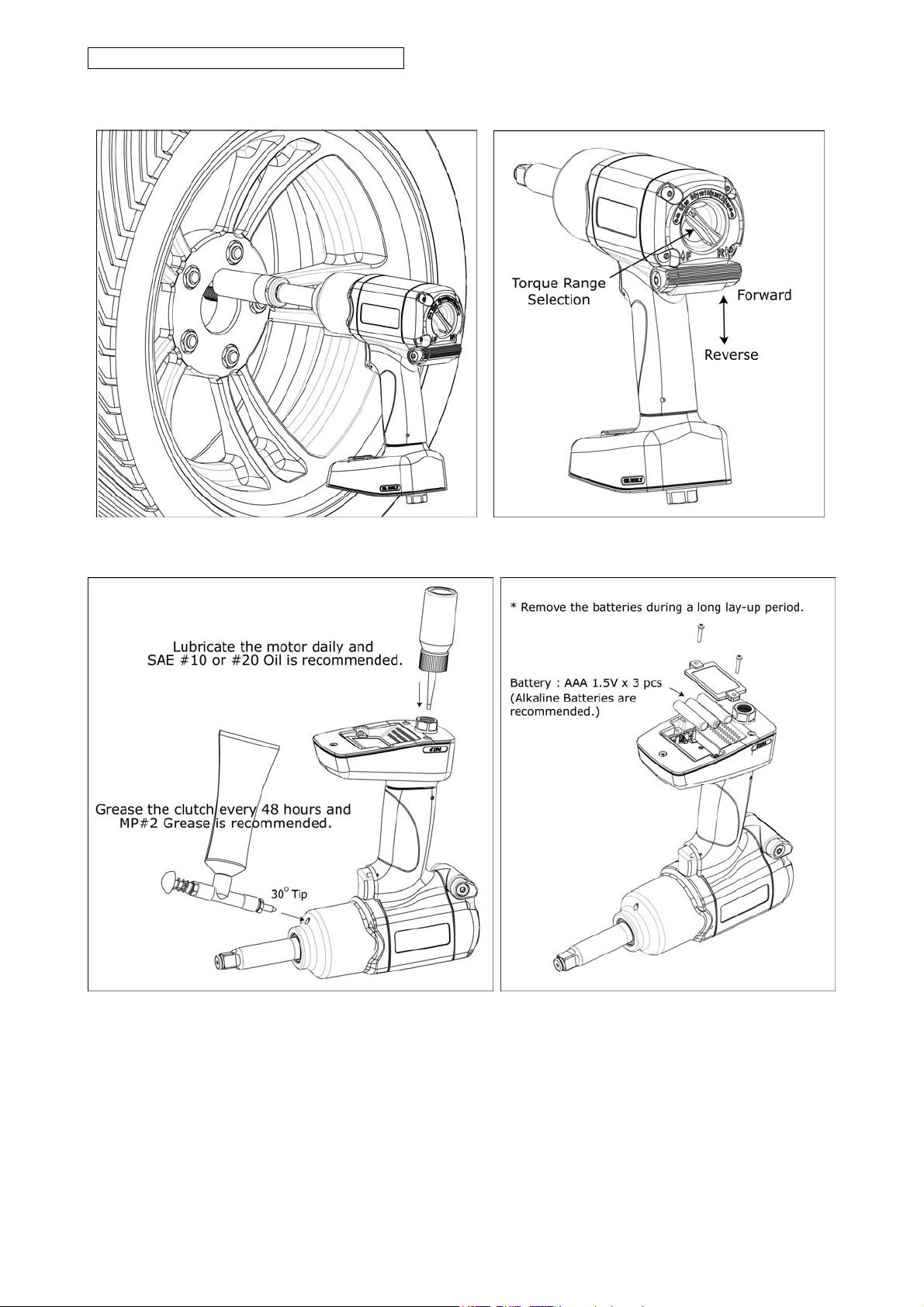
Always ensure that the reverse button is in the selected position before starting the
tool. P.5/6

Do not use sockets with excessive wear to the input and output drives.
Periodically check the square drive on the impact wrench.
Make sure the socket, extension is firmly fixed to the tool.
When loosening fasteners, first ensure that there is sufficient clearance behind the
tool to avoid hand entrapment. The tool will move away from the threaded joint as
the nut/bolt is loosened and rides up in the thread moving the tool with it.
It is expected that users will adopt safe working practices and observe all relevant
legal requirements when installing, using or maintaining the tool.
Proper Use Of The Tool
The tool is designed to be used only for the purpose of driving, tightening and
loosening of threaded fasteners, usually nuts and bolts, when fitted with a suitable
drive socket.
It is allowed to use impact-rated extension bars, universal joints and socket adapters
between the square output drive of the ratchet wrench and the female square drive
of the socket.
Do not use the tool for any other purpose than that specified without consulting the
manufacturer or the manufacturer's authorized supplier as this may be dangerous.
Never use the tool as a hammer to dislodge or straighten cross threaded fasteners.
P.6/6

1305
Technical
Details
7.22
6.23
Speed
RPM
Square
Drive
Max. Torque
Nm/ft-lb
Length
mm/inch
Weight
kg/lb
Air Consumption
LPM / CFM
Air Inlet
inch
Vibration
m/s
Working Pressure
Bar / PSI
Noise (DB)
LpA LwA
Uncertainty(DB)
KpA KwA
95.5 106.5 3
24290
24290L
7,500 1/2 880 (650)
197 (7.8)
248 (9.8)
2.6 (5.7)
2.7 (5.9) 132 (4.6) 1/4 6.2(90)
* Due to our continuous improvement, all specifications are subject to change without prior notice.
41
42
50
1
2
3
49
5
4
7
8
9
11
6
10
12
13
14
15
16
17
18
19
20
21
22
23
24 26
25
37
27
34
28
29
30
31 32
33
35
36 36-1
36-2
36-3
36-4
36-5
36-6
43
39
38
45 46
47
48
51
21
40
50
Index No. Description Quantity Index No. Description Quantity Index No. Description Quantity
01 Front Casing Set 1 20 O-Ring 1 36-3 Seal 1
02 Packing 1 21 Steel Ball 2 36-4 Washer 1
03 Anvil Set for 24290 1 22 Spring 1 36-5 Retaining Ring 1
04 Hammer Cage 1 23 Trigger 1 36-6 O-Ring 1
05 Hammer Pin 2 24 O-Ring 1 37 Spring Pin 1
06 Hammer 2 25 Housing 1 38 Muffler 1
07 Ball Bearing 1 26 Spring Pin 1 39 Tube 1
08 Front Plate 1 27 Packing 1 40 Quick Joint 1
09 Rotor 1 28 Cover 1 41 Filter 1
10 Rotor Blade 7 29 For. / Rev. Director 1 42 Tube 1
11 Spring 7 30 Pin 1 43 Digital Gauge Asses. 1
12 Spring pin 1 31 O-Ring 2 44 3A Battery 3
13 Cylinder 1 32 Knob 1 45 Screw 4
14 Adaptor 1 33 Screw 2 46 Cover 1
15 Rear Plate 1 34 Knob 1 47 Screw 2
16 O-Ring 2 35 Screw 4 48 Screw 1
17 O-Ring 1 36 Air Inlet w/preset 1 49 2" Anvil Set for 24290L 1
18 Ball Bearing 1 36-1 Spring 1 50 Clip Ring 2
19 Regulator Knob 1 36-2 Pin Valve Rod 1 51 Spring 1
Patented: I411501
R
This manual suits for next models
1
Table of contents