Pocket home PH-BHD User manual

Wireless control unit
Two-way radio communication on 433.92 MHz
Comfortable solution of room heating
Predictive system (providing for the given temperature at the required time, in autonomous mode only)
Energy cost saving during holiday
Control of room temperature according to preset requirements
PH-BHD
Operating instructions PH-BHD
version 11.08
WIRELESS CONTROL UNIT
FOR CONTROL OF DIGITAL RADIATOR CONTROLLERS
(WITHIN ONE ROOM)
Possibility of integration in the PocketHome®system, in which it becomes
a subordinate element of the central unit PH-CJ37 / PH-CJ37 Plus

SYSTEM FUNCTIONS
PH-BHD wireless control unit
- measures temperature in the room and controls the individual heating devices centrally as
required (functions as a room thermostat);
- function is similar as wireless temperature sensor
- able to control up to 255 elements (PH-HD01, PH-HD20) from one place;
- identifies the current status of activated system components
- for control by means of a mobile phone, you just need to connect the GST1/ GST2 module
(page 9, 12, 13);
- can be integrated in the PocketHome®system, in which in becomes a subordinate element of
the central unit PH-CJ37/ PH-CJ37 Plus and meets its requirements.
2
SYSTEM COMPONENTS
This wireless two-way system is primarily designed for the regulation of radiators in a single room. Here, the control unit fulfils the of
a wireless room thermostat (tempearature sensor). According to the temperature in the reference room, in which it is located, it controls
the radiator valve and regulates the whole heating system according to the preset program. It enables control of up to 255 radiators
(radiator controllers) from one place. The control unit sends information on the required temperature to individual controllers;on the basis
of this information, each controller controls the radiator to which it is connected.
PH-HD20 wireless digital radiator controller
- it senses current temperature in the room
- it receives information on required temperature from central unit
- on the basis of the information obtained it controls the position of radiator valve
- it sends back confirmation of the change made and also failure conditions
- it is able to work also in autonomous mode
- it is powered economically by alkaline batteries 2x1.5 V of AA type
PH-HD1 wireless digital radiator controller without LCD
- it receives information on required temperature from central unit
- on the basis of the information obtained it controls the position of radiator valve
- it sends back confirmation of the change made and also failure conditions
- it indicates function by color LED
- it is powered economically by alkaline batteries 2x1.5 V of AA type
PERMEABILITY OF VARIOUS MATERIALS FOR RF SIGNAL 433.92 MHz
wall
plasterboard
glass reinforced concrete
iron
Note: The above mentioned values are only approximate; they may vary because of specific conditions
at the location of signal transmission and reception!
In order to prevent interference and affecting of the systems, each of them is protected by its own unique code which is stored in the
control unit PH-BHD by the manufacturer!
Correct communication of all system components with the control unit PH-BHD requires code learning - ACTIVATION of each
component added to the system!
!
!
As the whole system works at bidirectional radio frequency of 433.92 MHz, observe the instructions for installation and location of each
system component according to the given manual!
!

3
LOCATION OF BATTERIES AND THEIR REPLACEMENT
control
buttons
battery
compartment
- Open the battery compartment cover and remove the protective paper; now PH-BHD is functional.
- When replacing batteries, pay attention to correct polarity, as shown in the battery compartment.
- Low battery is indicated by the symbol flashing on the display.
- Use solely alkaline pencil-type batteries 2x1.5 V, AA type!
Dispose of old batteries in compliance with the regulations related to the handling of dangerous waste!
!
DESCRIPTION OF PH-BHD
stand installation
1.
2.
3.
Note: The stand
is supplied with
PH-BHD
character display
connector for
GST module
Connector for
external source
(5 to 12V/ DC min. 150
mA) 0 V
5 to 12 V
internal antenna
GSM modules
Note: The external source
and GSM modules are not
included in PH-BHD!
We recommend you
to use the external
source (AD05) if the
system contains more
than 10 elements!

4
DESCRIPTION OF CONTROLS ON PH-BHD
change of temperature
change in the setting of clock and constants
browsing in the course of function selection
enter (confirmation)
display of information on required temperature
and operating hours and position of valve in %
change of time (in PROG mode)
setting the date and time (in holiday mode “ ” )
browsing among elements (in ACTIV and INFO mode)
shift for setting the constant 17 – phone. No. (in
CONST mode)
selection of program for controller (in AUTO mode)
switching between programs (in PROG mode)
switching between constants (in CONST mode)
switching between temperatures “ and ” (in MANU
mode) component adding (in ACTIV mode)
reset of operating hours
component deactivation (in ACTIV mode)
switching all components off (in AUTO, MANU mode)
copying of days (in PROG mode)
dovolená (v tomto režimu nelze zobrazovat info)
volba SUDÝ/LICHÝ týden (v režimu PROG)
change of day (in PROG mode) testování správného připojení (hlavice,
GSM modulu)
testování jednotlivých hlavic (v režimu ACTIV, INFO)
selection of function (mode), see p.6
AUTO, MANU, CLOCK, PROG, CONST, ACTIV, INFO,
UAdr
reset
H
+--
T
+
--
i
P
+
--
Off
Copy
Day Test
FR
DESCRIPTION OF THE PH-BHD DISPLAY
current day indication
symbol of current date and time setting, see page 6
indication of active communication
variable part of the display, indication of current time and
required temperature / program number, indication of other
information is explained in detail with every mode
economy temperature indication (in MANU mode)
summer mode symbol, see page 8
comfortable temperature indication (in MANU mode)
error message, error notice
anti-freeze mode symbol, see page 11
holiday mode symbol, see page 11
low battery indication
signal transmission / reception indication
variable part of the display, indication of current temperature
and selected mode (OFF, AUTO, MANU, PROG), indication of
other information is explained in detail with every mode
program interval indication (max. 6 intervals per day)

5
ACTIVATION PROCEDURE IN THE PocketHome®SYSTEM
After PH-BHD activation in the PocketHome®system, the control unit will be controlled by the central unit
PH-CJ37(Plus). On the basis of the temperature measured in the room and the information received (on the
temperature required) from the central unit, will be control of controllers (by PH-HD20 or PH-HD01).
Note: The activation can also be done via a PC. Connect the PH-CJ37(Plus) to the PC and start the PocketHome®software; follow the
instructions for the software.
1. PH-BHD ACTIVATION
- Add the new bHd element in the central unit PH-CJ37(Plus) (ACTIV, page 12,
in the central unit instructions), including the temperature program.
- Press the button on the PH-BHD unit, and choose the UAdr mode with
the buttons and confirm by button.
- Press the button on PH-CJ37(Plus); the central unit sends a signal to PH-BHD
- After correct signal is received, PH-BHD displays the unique number of the central
unit and the address allocated.
- Within 2 minutes, the central unit sends repeated signals to PH-BHD; or if you
press the button to speed up the communication.
- PH-BHD displays the bEZ:dr message and the unit is fully controlled by
the PH-CJ-37(Plus) central unit.
Test
Test
i+/- T
F
Unique num-
ber of the
central unit
Allocated
address of the
central unit
Indication of the BHD unit state in the PocketHome®system
OPENED
CLOSED
state of vlave Description
AUTO and MANU are simultaneously shown on the display
AUTO and MANU are simultaneously flashing on the display
1)TIME - If the time is changed in PH-CJ37(Plus), it will automatically be transmitted; PH-CJ37(Plus) shows the
“bHd” message shortly, and the time will be synchronized.
2) PROGRAMS - programs are not set on PH-BHD, since you can choose it on PH-CJ37(Plus) directly.
Other automatic functions:
3) Boiler state message – twice an hour, PH-CJ37(Plus) sends information on the boiler state to all elements
(“bHd” is displayed again), and the “t : Hr“ message (e.g. general test) appears on PH-BHD.
2. SETTING OF PH-BHD CONTANTS
Follow the instructions on page 8 CONST11 to CONST13 will not be displayed in this mode.
3. ACTIVATION OF CONTROLLERS
Follow the instructions on page 9-10. Do not set the program for radiator controllers, the required temperature
is transferred from PH-CJ37(Plus).
WHAT YOU NEED NOT SET?
ACTIVATION PROCEDURE IN THE AUTONOMOUS MODE
PH-BHD can work as an independent control unit which controls elements within one room. This mode is autonomous
– independent of the central unit PH-CJ37(Plus). This mode is suitable for heating within one room. For the setting,
see below.
In connection with the central unit, PH-BHD is a subordinate element. The required temperature is received from the
central unit (the AUTO mode is not accessible on PH-BHD).
A short-time temperature change in the room in which PH-BHD is located can be made with the button
on PH-BHD directly, but only until the next program change in the central unit!
+/- T

The system functions in the manual mode.
VWithin this mode, two required temperatures may be set: the economy
and comfortable . Selection and setting are made with the and buttons.
+/- T+/- P
Display options on LCD:
line 1 - current day
line 3 - from the left: current time or error states, required temperature
line 4 - selected temperature: economy or comfortable
line 5 - current temperature and selected mode
6
DESCRIPTION OF PH-BHD FUNCTIONS AND THEIR SETTING
Make sure you have carefully studied the introductory part of the instructions with the description of the unit, battery
location, functions of buttons and symbols on the display (LCD)!
The next part is focused on explanation of basic modes and setting of important parameters for correct function of
the entire system.
AUTO
The system functions in automatic mode according to the program preset.
Change of the program is made by pressing the button.
Following information is displayed when button is pressed:
- required temperature; short-term change of the temperature can be made
by pressing the button (page 11)
- operating hours; pressing the button resets the counter
- position of valve in %
Off
+/- T
i
+/- P
Display options on LCD:
line 1 - current day
line 3 - from the left: current time or error states, required temperature or program number
line 5 - current temperature and selected mode
line 6 - program interval
MANU
CLOCK
automatic mode (not accessible in the PH system)
manual mode
setting of current time and date
By means of the buttons, successively set hours, confirm by pressing button;
minutes, confirm by pressing button;
seconds, confirm by pressing button;
day, confirm by pressing button;
month, confirm by pressing button;
and year, confirm by pressing button.
i
i
i
i
i
i+/- T
PROG programming
The control unit fulfils the functions of a room thermostat and enables setting of up to 9
different weekly programs.
For each day, up to 6 time intervals can be set with various temperatures.
Upon first activation, programs 3-9 are set by default (can also be changed).
In program 1 and 2, you can set even and odd weeks, which will change automatically
according to requirements (page 7).
! After activation of PH-BHD in the PocketHome® system, programs cannot be
changed; requirements are directly sent from the central unit PH-CJ37(Plus).
Press the button and by means of the buttons browse the individual modes, confirm the mode selection
by pressing the button.
i
+/- TF
l.1
l.2
l.3
l.4
l.5
l.6

7
Direct programming on PH-BHD
- Press the button and select the PROG mode by means of the buttons; confirm by
pressing the button.
- By pressing the buttons, select the program, which should be set (1.P to 9.P).
- Press buttons to set the beginning of the temperature change, with the minimum step
of 10 minutes.
- Assign the required temperature to the given time by pressing the buttons by steps
of 0.5 °C.
- After setting the first time and temperature, press the button to confirm.
- You are automatically shifted to setting of the second time and temperature for the same day,
as indicated by symbol on the last, sixth line of the display.
- Continue in the same way until you set the last (sixth) interval.
- By pressing the button, you will automatically move to the setting of the next day, where
you can proceed in the same way.
i
2
i
+/- T
+/- H
+/- P
i
+/- TF
Info: If not all of the 6 settings for one day are needed, it is possible to move to the next day by successively
pressing the button or the button.
Day
i
Copying of days in PROG mode
- The day indicator must be on the day which you want to copy to the next day.
- Press the button, the program will copy itself automatically to the next day and the day indicator (line 1 of
the display) moves to the next day.
Copy
Selection of even or odd week in PROG mode
If you have set programs 1.P and 2.P, you can define which one will be active in odd or even weeks. When this
option is selected, the programs will alternate each week in the AUTO mode automatically (suitable for work in
shifts).
- Press the button and select the PROG mode by means of the
buttons; confirm by pressing the button.
- By pressing the buttons, select program 1.P
- Press the button and specify the week in which the program will be
active: L = odd, U = even, 1= not defined
- program 2.P will be defined automatically.
+/- P
i
+/- TF
Pre-set factory programs
Programs 3.P to 9.P are factory pre-set, but can be changed as necessary like 1.P and 2.P.
(example: item 5/21 means that at 5 o'clock, the required temperature is 21°C )
ODD
EVEN
This function accelerates programming. Program for one day can be copied to the next day by simply pressing the
button.
Copy
Note: When changing the preset programs, check all of the 6 time intervals!
Monday
Tuesday
Wednesday
Thursday
Friday
Saturday
Sunday
program No.3
Monday
Tuesday
Wednesday
Thursday
Friday
Saturday
Sunday
program No.4
Monday
Tuesday
Wednesday
Thursday
Friday
Saturday
Sunday
program No.5
Monday
Tuesday
Wednesday
Thursday
Friday
Saturday
Sunday
program No.6
Monday
Tuesday
Wednesday
Thursday
Friday
Saturday
Sunday
program No.7
Monday
Tuesday
Wednesday
Thursday
Friday
Saturday
Sunday
program No.8
Monday
Tuesday
Wednesday
Thursday
Friday
Saturday
Sunday
program No.9

8
15. CORRECTION OF REFERENCE POINT - FORCE OF CONTROLLER WHEN TIGHTENING THE VALVE
Set the force of controller during tightening the valve in the range from 1 to 5.
By pressing buttons set value and confirm by .
+/- T i
Examples:
1. Controller flows water even if is closed on 0 percent – increase this parameter at 4 or 5.
2. Controller begins to leak water to over 50 % - decrease the value constant to 2 or 1.
CORRECTION OF REFERENCE POINT:
used to accurately set the reference point during adaptation controller on the valve. It
moves in steps 1-5, and the factory default is set to a value of 3. This value cannot
majority needed to change. Change this parameter if the head is unable to adapt to the
valve and reports ERROR or controller flows the water even if valve is closed. Correction
is also needed in older valves squeezed sealing rings or valves, which place greater
mechanical resistance. The larger number, the greater the power of controller during
tighten the valve.
CONST
For correct thermostat function of the control unit, you must set the following constants
which define, for example, the temperature limits or method of control (hysteresis or
PI regulation).
setting the constants
- press button and by means of select CONST mode, confirm by pressing .
- press buttons to display individual constants (see below).
- set by pressing buttons, again confirm by button.
i+/- T
+/- P
i+/- TF
1. MINIMUM REGULATED TEMPERATURE
2. MAXIMUM REGULATED TEMPERATURE
Here you set the limits of the minimum adjustable temperature.
You can select in the range from 2° C to 10 °C.
Make the setting and press the button to move to the next constant setting
automatically.
i
Here you set the limits of the maximum adjustable temperature.
You can select in the range from 15° C to 39 °C.
Make the setting and press the button to move to the next constant setting
automatically.
i
3. EARLY SWITCH-ON OF THE HEATING SYSTEM / SUMMER MODE
By pressing buttons, select one of the following modes and confirm by pressing the
button (! If PH-BHD is controlled by the central unit, this constant is not shown).
i
+/- T
Option 0 = normal mode
Normal operation of the heating system, without early switch-on of the heating.
Option 1 = early switch-on of the heating
This function guarantees you the required temperature at the required time.
You need not guess when to switch the heating on in order to have the adequate temperature in the morning when getting up without
heating long in advance unnecessarily. You only program the time of the required temperature. In two days of operation, PH-BHD
establishes the thermal constants of the room and then switches the heating on at the required time in advance. The early switch-on
period is limited to 2 hours.
Option 2 = summer mode
In this mode, the heating cannot be switched on. It is useful especially in the summer period, when heating is not necessary. When this
mode is activated, the " " symbol appears on the display.
Note: The anti-freeze protection (3°C) is still functional. In this mode, it is not possible to change the temperature and set the
holiday mode!
(in autonomous mode only)

9
20. FIRMWARE VERSION
This constant cannot be set, it just informs you on the firmware version.
ACTIV activation of radiator controllers
This mode enables you to add (activate) successively the system controllers and
assign temperature programs to them.
The maximum number of all the system controllers is 255!
-Press the button and select the ACTIV mode by pressing the
buttons; confirm by pressing the button.
-The option for program selection for controller PROGR appears on the LCD.
-Assign the 1.P to 9.P program with the buttons and confirm with the button.
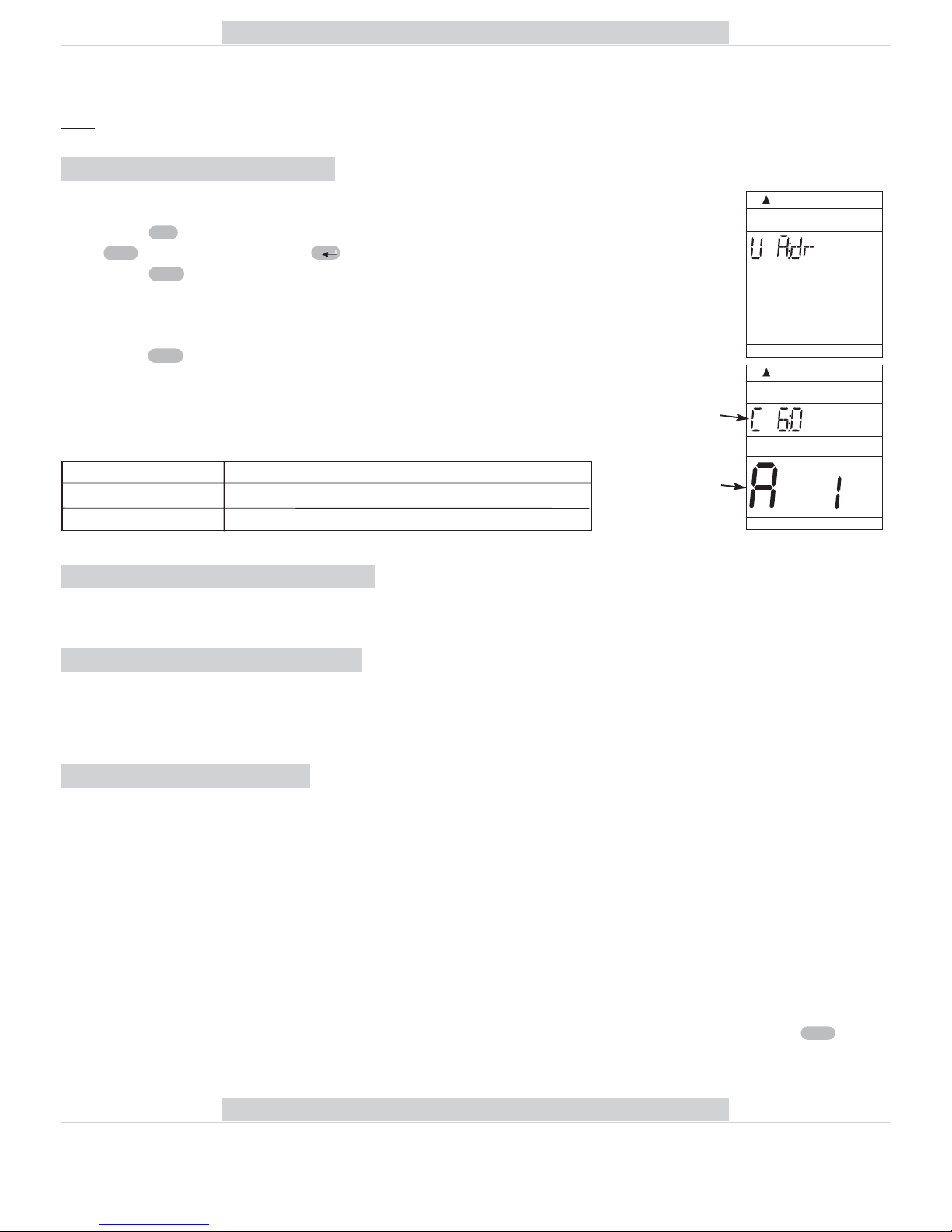
-In the next step, activate step-by-step the Hd1 až Hd255 radiator controllers.
-Press the button, in which way you define the address of the first controller
(Hd : 1) (the number in line 5 informs you about the total number of active controller)
- Set the mode for activation (depending type of controller, see page 10)
- Press the button on PH-BHD (the signal transmission symbol appears as well
as the symbol of communication with the element).
- The controller will indicate reception the signal and the controller is activated!
If the UCENI message appears on PH-BHD, some of the controllers have not been enabled
correctly! Choose the radiator controller step-by-step and test them with the button. If
the Err message appears with an element, enable it again according to the above procedure.
Test
Test
+/- P
i+/- T
i
+/- TF
total number
of active
elements
CAUTION: If controller is in adaptation mode or controls (spin motorized), not receive or
transmit signal! During activation be careful and when controller not registered
into the system, use button again.
Test
17. SELECTION OF CONTROL VIA GSM MODULE
By means of this constant, you can select the option to control the central unit via GSM module.
Options:
GSM: N GSM module is not enabled, constants 18 and 19 are automatically omitted.
GSM: A GSM module is enabled, it is necessary to set the constants 18 and 19!
Select by pressing the buttons and confirm by the button.
(The control via GSM module is described in detail in the manual for GST1/GST2)
! After activation of PH-BHD in the PocketHome®system, this constant is not displayed!
(The GSM module controls the central unit PH-CJ37/Plus).
i+/- T
18. SETTING THE TELEPHONE NUMBER
This constant can only be set for the version with the option of connecting the
GST1/GST2 module enabling the control via mobile phone (see p. 12-13).
Set the telephone number in international format (e.g. 420123456789), to which SMS
messages informing about the thermostat condition should be sent.
Set by pressing the buttons and confirm by the button.
You can browse the numbers with the buttons.
HDSP in the PocketHome®system, this constant is not displayed!
(The GSM module controls the central unit PH-CJ37/Plus).
+/- H
i+/- T
19. SETTING THE PIN CODE OF THE SIM CARD USED
This constant can only be set for the version with the option of connecting the
GST1/GST2 module enabling the control via mobile phone (see p. 12-13).
Set the PIN code of the SIM card inserted in the GST1/GST2 module.
Set by pressing the buttons and confirm by the button.
You can browse the numbers with the buttons.
! After activation of PH-BHD in the PocketHome®system, this constant is not displayed!
(The GSM module controls the central unit PH-CJ37/Plus).
+/- H
i+/- T
(in autonomous mode only)

10
You can browse the individual controllers with the button.
+/- H
PH-HD01 CONTROLLER ACTIVATION:
- Press “FUNCTION BUTTON ” on the controller (for approx. 1,5 s) thus you enter the
code learning mode (see the PH-HD01 instructions).
- Press the button on PH-BHD (the signal transmission symbol appears as
well as the symbol of communication with the element).
- Two diodes flash simultaneously on the switching element; thus the element is ENABLED!
If Err appears on the display of PH-BHD, you must check the connection and repeat the procedure!
- Add the next controller with the button , the button defines the address of the
second controller (Hd : 2); then repeat the procedure as during the activation of the first
element.
PH-HD20 CONTROLLER ACTIVATION:
- Select function for controller activation “ UA:dr” (see PH-HD20 instruction).
- Press the button on PH-BSP (the signal transmission symbol appears as well
as the symbol of communication with the element).
- Press againg and check correct function of controller.
- AUTO+MANU items are shown on the display simultaneously and controller is activated!
- Repeat the procedure for other controller
If Err appears on the display of PH-BHD, you must check the connection and repeat the procedure!
Test
Test
+/- P+/- H
Test
You can disable the controller with the button (in ACTIV mode).
Off
element address
(sequence number)
total number
of elements
INFO information on individual components activated within the system
In this mode, you can obtain information on the condition of individual system
controllers.
total number
of components
of the whole
system
-Press the button and select the INFO mode with the buttons;
confirm by pressing the button.
-nInformation on the selected program PROGR (*) appears on the display
1. By pressing the button, you can change the temperature for the given mode.
-If you press the button, information on the Hd: 1 switching component appears on
the display
1. required temperature;
2. selected mode (AUTO, MANU);
3. preset program.
-By pressing the button, you can check position of valve in %
-nformation on other controllers can be obtained by pressing the button.
* If PH-BHD is activated in the PocketHome®system, the program number is
not displayed (the required temperature from the central unit is displayed).
+/- H
Test
i
+/- T
i
+/- TF
BROWSING the controllers
DISABLING of a controller
!
!
UAdr activation in the PocketHome®system (see page 5)
central unit
unique
number
address
assigned by
the central unit
- Add the new BHD component in PH-CJ37/Plus (ACTIV,
page 12 in the central unit instructions).
- On the PH-BHDP unit, press the button and select the
UAdr mode with the buttons.
- Confirm with the button.
- Press the button on PH-CJ37.
If the activation was correct, the unique number and assigned ad-
dress appear on PH-BHD. PH-BHD becomes a subordinate unit,
waiting for orders from the central unit!
Test
i
+/- T
F

11
FURTHER FUNCTIONS
HOLIDAY
This function is very useful at the holiday time when the house is empty and it is not
necessary to change the temperature.
Always set the DATE and HOUR of your return from holiday, when you want PH-BHD to
return to the defined program (in AUTO or MANU)!
- Select AUTO or MANU mode
- Press the button.
- By pressing the buttons, set the date of return from holiday and confirm by
pressing the button.
- Set the time of return and again confirm by pressing the button.
- By pressing the buttons, set the temperature which will be kept throughout your
holiday until you come back.
- After approx. 30 seconds, the central unit switches to the holiday mode.
+/- T
i
i
+/- H
In this mode, the buttons are not functional (with the exception of Off and ) !
!This mode can only be cancelled by pressing the button!
SHORT-TERM TEMPERATURE CHANGE IN AUTO MODE
This function is possible in the AUTO mode; by simply pressing the
buttons, set a temperature different from that specified in the program.
PH-BHD will maintain this temperature until the next change specified in the program.
+/- T
RESET
The button can only be used in case of an indefinable error - when pressed, the processor is reset, but all the
changes made will remain stored in the E-EPROM memory!
To reset all of the parameters and programs defined (programs 3 to 9 will return to factory settings), press the
and buttons, release the button, and then the button (the RESET message appears shortly on the LCD).
OffRR
Off
R
This function can be used if the current room temperature does not suit you at the
moment and you need to change it for a short time without any change to the program.
ANTI-FREEZE MODE
If the room temperature drops under 3 °C, PH-BHD automatically sends a command to switch the boiler on.
As soon as the temperature increases, it returns back to the preset mode.
OPEN WINDOW” FUNCTION
If the temperature in room changes suddenly (for example because of window opening, change of 1.2 °C within
2 minutes), controller closes the valve and so saves energy. This condition is indicated by symbol „OKNO“ on the
PH-BHD display. The mode is terminated when the temperature rises or till 30 minutes. To further the mode „open
window“ may be possible after 10 minutes and after temperature decrease of 1.2 °C.
This mode cannot be selected in SUMMER mode (constant 3 is set, symbol )!
If PH-BHD is activated in the PocketHome®system, the holiday is directly set
on the central unit PH-CJ37/Plus!
CONNECTION OF GST1/GST2 MODULE
The system can be extended with the GSM module - GST1/GST2, which provides for remote control of the control
unit via a mobile phone. By means of simple SMS messages, you can control the heating or obtain information on the
system condition. For detailed instructions, see the GST1/GST2 module (the module connection option is selected
by CONST 17-19, page 9).
(cannot be used if PH-BHD is controlled by the central unit!)
(in autonomous mode only)

12
DESCRIPTION OF SETTINGS IF THE GSM MODULE IS USED
FOR CORRECT PUTTING INTO OPERATION, THE FOLLOWING PROCEDURE MUST BE OBSERVED!
1. Make installation and setting of the control unit according to the instructions.
2. Constants 17, 18 and 19 must be set on the control unit as follows:
SETTING THE TELEPHONE NUMBER - CONST 18
Set the telephone number, in the international format (e.g. 420123456789), to which
SMS return messages informing about the thermostat condition should be sent.
Set by pressing buttons and confirm with the button.
You can browse the numbers set with the buttons.
+/- H
+/- T i
SETTING THE PIN CODE OF THE SIM CARD - CONST 19
Set the PIN code of the SIM card inserted in the GST1/GST2 module.
Set by pressing the buttons and confirm with the button.
You can browse the numbers with the button.
+/- H
+/- T i
Thanks to this function, you need not remember the PIN code of the SIM card inserted in the
module connected to control unit. After entering the PIN code (according to the below
procedure) in the control unit, connect the module and then connect it to the mains. Within
approx. 3 minutes, the PIN code is automatically sent from the control unit to the module, thus
the module becomes active (to accelerate the activation, use the button on the control
unit).
Test
3. Insert the activated SIM card into the GST1/GST2 module. For more details, see the GST1/GST2 instructions.
4. Interconnect the control unit and the module by means of a data cable (included in the GST1/GST2
packing), and then connect the module supply unit to the 230 V / 50 Hz mains
(the orange LED is flashing)!
5. As soon as the orange diode on GST1 is alight, test the correct connection by pressing the button on the
control unit. One of the following messages appears on the display of the control unit (the connection is always
automatically established within 3 minutes):
Test
Signalizes correct connection of the module. Signalizes correct connection of the module and
PIN code setting.
The module is not connected, incorrect
connection of the module!
Signalizes correct connection of the module, but
incorrect PIN code setting! It is necessary to
disconnect the module, RESET the control unit
and set the correct PIN code!
SELECTION OF CONTROL VIA GSM MODULE - CONST 17
By pressing the buttons, select the GSM: A option and confirm with the button.
+/- T i

13
Info HD
Off HD
Temp xx HD
Call
Switching the HD components off. To abolish the function, use the Temp xx HD
message
(if in the AUTO mode, the state is valid until the next program change).
xx = temperature value in°C (always a two-digit number, e.g. 05)
Any type of mobile phone can be used for sending and receiving of return messages!!
If font size (format) can be adjusted in the phone, always use the MEDIUM size for messages (when
three sizes are available) or the LARGE (when two sizes are available).
!
WORDING OF RETURN MESSAGES FROM THE CONTROL UNIT
Requir: xx.x
Act: xx.x
On
Sig: x
required temperature (entered by the user)
current temperature in the room
heating system on
defines signal strength at the place of the module location;
where xare values ranging from 0 to 5:
0..cannot be determined or no signal detected
1..the worst strength
5..the best signal strength
Off
heating system off
AUTO
automatic mode AUTO
MANU
manual mode MANU
Battery!
signalizes a discharged battery in the central unit
incorrect SMS message or communication error
Incorrect SMS or can not be
identified selected device
xx.x = temperature in°C
Note: If the min/max room temperature is exceeded (as set by CONST1 and 2, see the PH-BHD manual, page 9),
the "WARNING" SMS message same as Info is automatically sent immediately.
Info: If a pre-paid card is used, it is necessary to make a paid call once in three months.
This call is made automatically (every 80 days, between 16 and 21 o'clock) to the number entered in the control
unit (CONST 18), and after 20 s, the call is terminated automatically. By means of the “Call” SMS message, you
can execute the function sooner.
RETURN MESSAGES ARE SENT WITHIN 3 MINUTES!
Pos xxx% valve opening in per cent
(where xxx is whole number from 0 to 100)
WORDING OF MESSAGES SENT
Information on the control unit condition
Change of the required temperature (where xx must be an integer
within the range of admissible maximum and minimum temperatures).
Back call

Power supply 2 x1,5 V alkaline pencil-type batteries AA
Communication type two-way
Frequency 433,92 MHz
HF output < 10 mW
Number of temperature changes 6 different temperature changes per every day
Minimum programmable time 10 minutes
Range of adjustable temperatures 3 to 39°C
Temperature setting step of 0,5°C
Minimum indication step 0,1°C
Measurement accuracy ±0,5°C
Battery life 1 to 3 years according to the battery type used
Protection class IP20
Operating temperature 0°C to +40°C
TECHNICAL PARAMETERS
In case of guarantee or post-guarantee service, send the unit to the manufacturer’s address.
DECLARATION OF CONFORMITY
We, ELEKTROBOCK CZ s.r.o., herewith declare that our product PH-BHD is in conformity with the basic requirements and other respective provisions of
the directive 1999/5/EC.
Issued: 1.09.2008 on www.elbock.cz
Using the PH-BHD in PocketHome®system:
Using the PH-BHD in autonomous system:
Objects with their own heat sources (eg family house)
Central unit PH-CJ37 plus control receiver of boiler PH-PK20 (PK21) in accordance with the requirements of the
various rooms in which are located control unit PH-BHD (which measures the temperature of the room). If in any of
the room (with assigned priorities) the temperature drops below the required level controller PH-BHD sends a request
warheads to open the valve. Subsequently, the central unit PH-CJ37 plus provide power to the boiler and heating of
the room. PH-CJ37 Plus you can activate up to 99 controllers PH-BHD ---> allows you to extend the system for larger
buildings within reach!
Objects without any heat source (flat with central heating)
Control unit PH-BHD measured of temperature in the reference room, where it is located. When the temperature
drops below the required level sends instructions to all controllers to open the valve. All controllers PH-HD01
(PH-HD20) work as one temperature program to set PH-BHD. This system is suitable for smaller objects.
In conjunction with the GSM module it is possible to operate the system remotely, using a mobile phone!
EXAMPLES OF PH-BHD IN PRACTICE
MADE IN CZECH REPUBLIC
ELEKTROBOCK CZ s.r.o.
Blanenská 1763
Kuřim 664 34
Tel./fax: +420 541 230 216
http:// www.elbock.cz
in compliance with RoHS
Pb
LEAD FREE
CERTIFICATE OF GUARANTEE
(guarantee period for the product amounts to 2 years)
product No.: date of sale:
stamp of shop:
examined by:
Table of contents
Popular Control Unit manuals by other brands

Dembla
Dembla 7500 Series instruction manual

Pickering
Pickering PXI BRIC 40-563A user manual

Fibocom
Fibocom G610 Hardware user manual

Cooper Security
Cooper Security Scantronic i-gsm02 Installation and programming guide

Land Pride
Land Pride 380-168A installation instructions

Floodcheck
Floodcheck NT2015 Guide