POCTech CT10 User manual

Copyright
The device bears CE mark indicating its conformity with the provisions of the Council Directive 93/42/EEC concerning
medical devices and fulfills the essential requirements of Annex I of this directive.
The CT10 Continuous Glucose Monitoring System is manufactured by Zhejiang POCTech Co., Ltd.
© Zhejiang POCTech Co., Ltd. All rights reserved. This User Manual may change without notice. When this happens, a new
issue of the User Manual will be released.
Definitions of Safety Notes
A WARNING statement provides important information about a potentially hazardous situation which, if not avoided, could
result in serious consequences.
A CAUTION statement provides important information about a potentially hazardous situation which, if not avoided, may
result in minor or moderate injury to the user or patient or damage to the medical device or other property.

A NOTE provides additional information intended to avoid inconvenience during operation.
Contents
Section 1. Safety Information
1.1. Important Safety Information
1.2. Labels
Section 2. Product Introduction
2.1. Intended Use
2.2. Contraindications
2.3. System Introduction
2.4. System Components
2.5. Receiver Menu Description
Section 3. Preparation before Use
3.1. Preparation before Use
Section 4. Product Operation and Notice
4.1. Using a New Sensor
4.2. Initialize the Sensor
4.3. Sensor Initialization and First Ref BG
4.4. Events Input
4.5. Features of the Touch-Screen Display
4.6. Care and Maintenance during Monitoring
4.7. Ending Your Continuous Glucose Monitoring
4.8. Waste Disposal
Section 5. Troubleshooting and Maintenance
5.1. Troubleshooting(with Error Code)
5.2. General Maintenance of Device -Inspection and Maintenance
Section 6. Specifications and EMC Declaration
6.1. Specifications
6.2. EMC Declaration
6.3.EU Radio Equipment Directive (RED) Declaration
Section 7. Warranty
7.1. Contacts and Numbers
7.2. Warranty

Section 1. Safety Information
1.1. Important Safety Information
Read this entire manual before using your Continuous Glucose Monitoring System. If you do not understand something or
have any questions, please ask your Diabetes Management Team or another health care provider. Contraindications,
warnings, precautions, cautions, and other important safety information can be found in this User Manual.
This device is not designed to replace a blood glucose meter. The system must be used with a blood glucose meter in
compliance with regulations.
•Treatment decisions should not be based solely on results from this device. You must confirm with a blood glucose meter
before making therapeutic adjustments.
•Symptoms related to low or high blood glucose levels should not be ignored. If you have symptoms of low or high glucose,
use your blood glucose meter to verify the results.
•You should update the device’s calibration according to the instruction in this manual to ensure device performance. The
performance of the device when calibrated less frequently than the recommendation has not been studied.
•The CGM product should be used under the supervision of a physician.
•Always wash hands with soap and water before opening the sensor package. After opening the package, avoid touching
the adhesive area.
•Before inserting the sensor, always clean the skin at the sensor insertion location with a topical antimicrobial solution such
as isopropyl alcohol. Do not apply the sensor until the cleaned area is dry.
•Establish a rotation schedule for choosing each new sensor location. Avoid sensor locations that are constrained by
clothing, accessories, or subjected to rigorous movement during exercise.
•Avoid injecting insulin or placing an insulin pump infusion set within 3 inches of a sensor.
•The sensor is sterile in its unopened, undamaged package. Do not use any sensor if its sterile package has been previously
damaged or opened.
•For calibration you must enter the exact finger stick reading that your blood glucose meter displays. Enter all finger stick
readings for calibration within 5 minutes. Entering incorrect finger stick readings that occurred more than 5 minutes ago
will affect device performance.
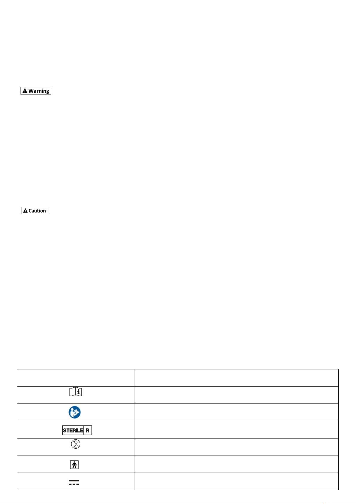
1.2. Labels:
Symbol label
Title of symbol
Consult instructions for use
Refer to instruction manual/ booklet
Sterilized using irradiation
Do not re-use
Type BF applied part
Direct current

Non-ionizing electromagnetic radiation
Symbol for the marking of electrical and electronic equipment
Batch code
Use-by date
Temperature limit (2℃~30℃)
IP27
Degrees of protection against water indicated
Manufacturer
Do not use if package is damaged
Date of manufacture
Authorized representative in the European Community

Section 2. Product Introduction
2.1. Intended Use
The device is indicated for detecting trends and tracking patterns in adults with diabetes. The system is intended for use by
patients.
This device is not designed to replace a blood glucose meter. The device must be used with a blood glucose meter.
Treatment decisions should not be based solely on results from the system. Treatment decisions must be confirmed with a
blood glucose meter before making therapeutic adjustments.
Indications
The system is indicated for detecting trends and tracking patterns in adults with diabetes. It is intended for use by patients
2.2. Contraindications
CT-Scan, X-Ray or MRI: If you must be examined with CT, X-ray, or MRI imaging, remove the transmitter and sensor. Start a
new sensor after the examination.
2.3. System Introduction:
Principle of Operation
The sensor works through enzymatic electrochemical reactions with glucose. The enzyme, glucose oxidase, allows glucose
to be converted into an electronic signal. The receiver converts the sensor signal to a glucose reading that is displayed to
the user.
The CT10 allows you to continually see your readings every 3 minutes for up to 10 days.
Reagents
Glucose oxidase. The enzyme glucose oxidase is derived from a microorganism Aspergillus niger purified and dried
according to Type VII-S guidelines. Direct tissue contact with the glucose oxidase is prevented by an outer sensor membrane
layer, therefore the risk of tissue reactions from glucose oxidase is considered to be minimal.
2.4. System Components
The system consists of three parts (Fig.1), a glucose sensor, a transmitter, and a receiver.
Figure 1. System: Sensor, Transmitter, and Receiver
•The sensor is a four electrode flexible tiny strip assembled with an inserter, packed in a sterile package for direct use.

Figure 2. The Sensor Assembly (Sensor & Inserter)
CT10 system components:
Part
1
1.1
CT-202 Sensor
2
2.1
CT-100C10 Transmitter
3
3.1
CT-100BD Receiver
4
4.1
User Manual
4.2
Quick Start Guide
4.3
Accessory: USB (Type C) Cable
4.4
Accessory: Battery Lid
4.5
Accessory: CR1620 Lithium ion button battery for CT-100C10 Transmitter(Option)
•Additional Supplies Needed:
Users should have a blood glucose meter readily accessible to make therapeutic adjustments and calibrate the CGM.
Users can choose to receive data using the receiver or POCTech CGM App. Users can download the POCTech CGM App
through the mobile application market. Used with the transmitter and sensor, the POCTech CGM App can collect, analyze,
transform and display the current data collected by the transmitter, store the collected data and generate reports.
Users can get the latest version of User Manual of POCTech CGM App at www.poctechcorp.com
Users can contact the supplier to obtain POCTech Care software for Windows, which is used to input the stored CGM data
into the computer through the USB cable to display the glucose data collected by the CGM.
2.5. Receiver Menu Description (Fig. 3):

Figure 3. Receiver Display
2.5.1 Top Status Line:
Date, Time; (yy-mm-dd)
Vibrator Alert; ( )
Remaining Sensor Days(10)
Audio Alert; ( )
Bluetooth; ( )
Battery. ( )
2.5.2 Middle Glucose Information:
Glucose Reading& Unit
Glucose Arrow
Glucose Trend Graph.
2.5.3 Bottom Menu Line:
Sensor ON/OFF/Signals ( );
Parameters Settings ( );
Events Input( );
Data Review ( ).
Sensor ON/OFF:
To turn transmitter data communication link ON/OFF (Fig.4): In normal operation mode, the “Sensor On” item is not
necessary. The sensor/transmitter connection initiates via the “Scan to search” operation. When a sensor is in data link
status, the “Sensor On” item is not operable. The “Sensor Off” is available only for particular cases when the monitoring
needs to be interrupted, or stopped before the end of the nominal 10-day period.
The “Sensor Signal” is for sensor status check purposes (trouble shooting) when abnormality is suspected.
The Sensor Menu can be opened by long pressing the icon (more than 3 seconds).

Figure 4. View Signal Screen
Parameters Settings (Fig. 5):
Date/Time;
Keypad Tone.
Alert On/Off (Audio/Vibrator/Audio+Vibrator).
Alert Setting (Hyperglycemia/Hypoglycemia threshold values).
Language .
Figure 5. Parameters Settings Menu
Events Input(Fig. 6):
RefBG: User enters Blood glucose (BG)
Event Input: User Logs:
Exercise;
Meal;
Medication;
Insulin.

Figure 6. Events Input
Data Review (Fig.7):
Review Data: Review historical sensor data.
24 Hours Data: Display a 24-hour Overlay of the selected sensor data file.
Figure 7. Data Menu

Section 3. Preparation before Use
3.1. Preparation before Use
The Sensor:
Check the sterile packaging and the expiration date to make sure that the sensor is in good condition.
The Transmitter:
Make sure that one new CR1620 (3V) cell button battery is available for each sensor when beginning the monitoring.
Prepare the transmitter (Fig.8): Install a CR1620 battery in the transmitter.
Figure 8. Install Transmitter Battery
Make sure the battery’s positive side is upward.
Tighten the battery chamber lid with a coin (Fig.9).
Figure 9. Tighten the Battery Lid
The transmitter starts wireless broadcasting. Its ID number will be displayed on the nearby receiver (When the receiver is in
Search Mode).
Figure 10. Transmitter ID Number
The Receiver:
Press and hold the power switch for more than 3 seconds to turn the receiver power ON. Verify that the date and time are

correct, and that the battery indicator indicates sufficient battery power.
When the transmitter has been successfully started, its ID number will be displayed on the receiver. Verify the number of
the transmitter. Touch the number on the screen to select the transmitter. And then “Yes” to connect the transmitter The
Bluetooth antenna icon appears on the receiver screen, indicating the data communication has been established. Then
choose “Sync” to synchronize the transmitter and the receiver (Fig. 11).
Figure 11. Identify Transmitter and Connect
Alcohol Pads and Medical Adhesive Dressing:
Have sufficient supplies available for skin cleaning, disinfection, and transmitter protection.

Section 4. Product Operation and Notice
4.1. Using a New Sensor
Prepare the Receiver:
When the receiver is turned ON, it searches for all nearby transmitters and displays a list of transmitters (or other Bluetooth
devices nearby).
Check receiver battery. Charge the battery if necessary.
Set Date and Time, Alerts Modes, Hyper/Hypo Thresholds, and Language
Prepare the Skin:
Choose one upper arm or middle abdomen for sensor insertion (Fig.12). Avoid scars or abnormal areas.
Use alcohol swabs (or pads) to clean and disinfect the skin.
Figure 12. Site Selection for Monitoring
Prepare the Sensor:
Examine the sensor sterile packaging.
Do not use if the package has been damaged.
Always check the expiration date on the sensor packaging before opening the sensor. Do not use expired sensors.
Tear open the sterile package to take out the sensor assembly. Remove the protection film on the sensor base adhesive
tape (Fig.13).
Figure 13. Peeling off Protection Film
Apply the Sensor:
Place the sensor on the cleaned skin.

Press the sensor base and the adhesive tape to achieve a firm adhesion(Fig.14).
Figure14.Press the sensor plate firmly to ensure adhesion
Remove the protection cap on the release button (Fig 15).
Bend down the inserter handle until the front sensor base plate pulls the skin up. (Figs. 16a).
Figure 16a.
Push the release button to trigger the insertion mechanism. The sensor should be inserted in the manner shown in Figure
16b.

Figure 16b. The Correct Insertion Angle
After sensor insertion, pull back to remove the inserter lock pin with the thumb of hand holding the inserter (Fig 17).
Figure 17. Remove the Lock Pin
Then, press the arms on the sides of the inserter to disengage the sensor. Remove and discard the inserter in medical sharp
disposal (Fig. 18).
Figure 18. Disengage and Separate the Inserter
Press down the Sensor Connection Block (Fig. 19):
Push the sensor connection block down to lock in the base.

Figure 19. Push the Sensor Connection Block into Position
4.2. Initialize the Sensor
The screen then displays “Start Sensor? Yes/No". When choosing “Yes”, the system enters next Initialization Mode and
begins to store sensor data (Fig.20).
Figure 20. Starting Sensor Data Acquisition
Install the transmitter to the sensor: Slide the transmitter onto the sensor base and lock (Fig. 21).
Figure 21. Sliding Transmitter onto Sensor and Lock
Place a medical adhesive dressing tape (3x4”, water proof) to cover the entire transmitter/sensor assembly if necessary.
4.3. Sensor Initialization and First Ref BG
The sensor requires a 1-hour initialization period. The countdown is displayed on the screen.
Due to physiological differences, blood glucose values within 2 hours after a meal or a high sugar drink cannot be used as
calibration references. It may result in significant error!
It is very important that you plan the time to begin your 1-hour initialization. The best time to implant the sensor is
immediately after breakfast or lunch so that the first calibration (after a 1-hour initialization) will be before next meal when
the blood glucose is in a steady state.
Once the initialization is complete, a reference finger blood glucose (BG) is required. Take a finger stick blood glucose (BG)
measurement, Select “ ”, and then “Ref BG Input” to enter the finger BG (Fig.22).

Figure 22. Entering Reference Blood Glucose
The sensor glucose value and a continuous glucose graph will be displayed after the BG entry (Fig. 23).
Figure 23. Receiver Display for Normal Glucose Monitoring
The sensor requires reference finger blood glucose (BG) for calibration. Follow the next Calibration Table to measure BG and
enter to the receiver within 5 minutes.
1st
2nd
Remark
1st Day
First BG
6-10 hrs after First BG.
The second BG should be before dinner or before bed.
2nd Day
a.m. Fasting
Before Dinner
Days 3-10
a.m. Fasting
NA
One BG daily for days 3-10
You must enter the fasting finger BG before breakfast. Do not enter BG readings within 2 hours after a meal.
4.4. Events Input:
The user should maintain a full activity log by entering all meals, exercise, medicine, and insulin, during the entire sensor
wearing period (Fig.24).
Figure 24. Events Log Menu Items

4.5. Features of the Receiver Touch-Screen Display
The Default Display: The default display includes a 5-hour glucose graph and a glucose value. The unit for glucose
concentration is mg/dL (mmol/L is available in countries where this unit is used). Normal graph and glucose concentration
are displayed in white. Press the HOME key on any screen to return to the default display.
Arrows: When an up or down arrow appears next to the glucose value, it indicates the glucose trend direction of change.
Hypoglycemia: The graph turns to red accompanied with an alert (beep or vibration) when the sensor glucose crosses
the pre-set threshold.
Hyperglycemia: The graph turns to yellow accompanied with an alert (beep or vibration) when the sensor glucose
crosses the pre-set threshold.
Events Marks: When the user enters an event log( ), the corresponding event mark appears on the glucose graph
(Fig.24).
Zoom-in or Zoom-out the timescale: Touch the bottom of the screen with a finger each time will cause the time scale to
zoom out 1/2; Touch the top of the screen with a finger each time will cause the time scale to zoom in doubles.
Left/Right Turn Pages: Touch the left or right sides of the screen moves one page each time.
Green colored Date/Time Means Review Mode: When you review the graph, the date/time display turns green, indicating
that the time is not the current clock time.
A Green vertical line and green glucose value is for review point value: Long press on any point of the glucose graph will
display a green line. The glucose value of this point is displayed in green.
24-hour Overlay: Touch the data icon< >to open the data review menu. Select the“24 hours data” to open a list of sensor
data files. Select the last file for the current sensor. A 24-hour overlay plot will be displayed.
Alert On and Off: The beep and vibration alerts are provided to you for unattended alert or reminder when an abnormal
situation occurs. To set the Alert Off, use the “Settings” menu( ) to select Alert On/Off, then choose “off”, “OK”, then
“confirm OFF”.
4.6. Care and Maintenance during Monitoring
Read the User Manual before using and operating the system. Users including physicians, nurses, and patients must be
trained.
Keep the receiver within 4 meters. The designated effective distance of the wireless communication is 4 meters. It is
recommended that you carry the receiver at all times. The alert function will not be available when the transmitter is not
linked.
Monitor the receiver battery indicator. Charge the battery whenever needed. Use the USB cable provided with this
system to charge the receiver. When the instrument has not been used for over a month, it should be charged once. Keep
away from fire and high electromagnetic fields. Avoid strong impact. When connecting to a power adapter or a computer, it
should be with an EN 62368-1 certified ME system.
Showering: The sensor/transmitter assembly, when properly installed and maintained, is water resistant to an Ingress
Protection Rating of IP27 ( submerging in water 1 meter/3 feet deep for up to 30 minutes). This means that you can take
showers without extra protection. However, due to differences in wearing times and differences in people’s skin conditions,
it is strongly recommended that you take necessary precaution and measures when engaging in activities involving water.
Sweating: Excessive sweating should be avoided. It may cause short circuit between sensor connections and adhesive
tape to become lose.
Accidental Loss of Sensor: In case the sensor comes off by accident, do not try to re-use. Report the incident or hand it to

your doctor.
Outdoor Activities: Avoid vigorous sports activities that might involve physical bumps.
Itchiness: Adhesive dressing tape usually may cause skin itchiness. This can be relieved by changing the cover dressing
tape every few days. When changing tape, be careful not to disturb the sensor. If swelling or redness accompanying
extreme itchiness happens under the sensor area, the sensor may need to be removed.
Avoiding Extreme Temperature: Try not to enter or stay in extreme temperature that is outside the specified range of the
system operation.
Strong Electromagnetic Fields: Avoid strong electromagnetic fields.
CT-Scan, X-Ray or MRI: If you must be examined with CT, X-ray, or MRI imaging, remove the transmitter and sensor. Start a
new sensor after the examination.
Effect on other Medical Equipment: Under extreme circumstances, nearby medical equipment may be affected. Refer to
IEC declaration.
Abnormal Signal: System malfunction, short circuit, sweating, water ingress, etc., may cause signal abnormality. If the
situation persists, remove the sensor and report the incident.
The receiver should not be placed close to other similar systems to avoid interference. Insulin pump users should not
place the sensor on the same side of the abdomen as the insulin infusion line.
The data system only functions with the designated sensors. Refer to related announcements by the manufacturer
regarding sensor compatibility in the future. Do not connect sensors with other unapproved devices or networks.
The information displayed by the receiver is intended to supplement instead of replacing a registered blood glucose
measurement device or instrument. It is intended to provide information on continuous changing glucose concentration
sand changing trends.
Avoid contact by small children. The system contains small parts that may present a choking risk if swallowed.
4.7. Ending Your Continuous Glucose Monitoring
The system is programmed to collect data for up to 10 full days. Data collection automatically terminates when the10-day
acquisition is complete.
Turn off the sensor from the Sensor Menu “ ” and remove the sensor together with the transmitter. When removing
the sensor from the skin, peel and lift the sensor base adhesive from one edge and pull up it firmly until the entire
sensor/transmitter assembly is separated from the skin. Do not discard the transmitter.
Check the skin site carefully for bleeding, infection, inflammation etc., if there is a concern, consult medical personnel.
Continue to use your BG meter for self-management of diabetes. Symptoms related to low or high blood glucose levels
should not be ignored. If you have symptoms of low or high glucose, use your blood glucose meter to verify.
4.8. Waste Disposal
Sensor: Dispose according to medical waste regulations.
Transmitter: Can be cleaned and reused. May be disposed as medical electronics.
Receiver: Can be cleaned and reused. May be disposed as medical electronics.
Battery: Disposal of the battery should meet local law and regulatory requirements.

Section 5. Troubleshooting and Maintenance
5.1. Troubleshooting
Receiver Memory Over-Flow. The receiver’s memory stores no less than 10 cycles of sensor’data. However, it is
recommended that you upload the sensor data to your computer (the desktop software can be obtained via customer
service or dealers). The Receiver automatically checks the memory space when it starts a new sensor. If there is not enough
memory for a sensor’s full data it will prompt user to delete old data files to free up memory space.
To delete a data file, go to data icon< >. Select “Review Data” to display a list of data files. Long press the file name you
want to delete and respond by selecting “Yes” to confirm the deletion.
Abnormal Sensor Signal. When the sensor signal is out of the expected range, the receiver will sound an alert. The
glucose display may be turned off. This usually occurs when water causes a short circuit. A partial pulling off of the sensor
may be another reason for alert for abnormal signal.
Sensor Failure. When a sensor failure has been confirmed by the system, the receiver will display “Sensor failure. Please
end the session.”
Issue establishing initial connection. If there is an issue establishing initial connection between the transmitter and
receiver, try powering the receiver off then on. If the issue still exists, replace the transmitter battery.
Transmitter Low Battery. The receiver receives the transmitter battery information when establishing initial connection. A
failure message will be displayed and a connection cannot be established if the transmitter battery is lower than 2.9V.
Simply replace a CR1620 battery and reconnect.
Receiver Low Battery. The receiver has a rechargeable battery. The battery indicator on the upper right corner changes
color when the battery is low. Make sure to check it regularly and charge the battery as needed. The battery normally has a
remaining operational time of more than 10 hours even when the indicator color turns orange, allowing enough time to
find a chance to charge.
When charging the receiver, a green battery indicator indicates the charging is in progress. It turns white when the charging
is complete. DO NOT unplug until the battery indicator turns WHITE.
Hyperglycemia Alert. The high glucose Alert is triggered when the sensor glucose is over the pre-set threshold value. It is
advisable not to set the hyper threshold below 200 mg/dl (11.1mmol/L) to avoid frequent alerts. It is strongly
recommended that a physician’s advice is sought.
Hypoglycemia Alert. Hypoglycemia Alert is the most important feature of the CGM device for patients who may have
hypoglycemic unawareness. The low glucose Alert is triggered when the sensor glucose is lower than the hypoglycemia
threshold (the default setting for hypoglycemia is 70mg/dL, or 3.9mmol/L). However, the registration condition of this
device requires a finger BG measurement to confirm the situation when a hypoglycemia event is detected by the sensor.
Blue-Tooth Communication Interruption. If the receiver alerts for lost communication during normal monitoring, it is
generally due to an out-of-range condition between the receiver and the transmitter. Bring them closer together to
re-connect.
Unexpected Sensor Removal. Although unlikely, the sensor may accidentally fall off, usually due to excessive sweating
or movement, or for people who have oily skin that makes it difficult for the sensor adhesive to adhere firmly. Do not re-use
the sensor. Start a new sensor.
Sensor Glucose Obviously Different From Experienced Judgment. When the sensor reading appears erroneous based on
personal experience, a finger stick BG measurement is recommended.
Water Ingression. See abnormal sensor signal.

Receiver Time Difference. You may notice that the time on the receiver is different from that of the actual clock. It is
normal as long as the time difference is within a few minutes. You are not allowed to reset the time during a sensor
monitoring session.
Damage or wear to the Transmitter Battery Lid. An additional battery lid is provided in the transmitter package. It should
be used whenever deformation in the O-ring or damage to the lid is observed.
Other Problems. Contact customer service.
Error Code List.
Error
Code
Receiver Display
Reason
Measure
E01
Receiver battery low! Please
charge the battery!
The receiver battery power is
too low.
Recharge the receiver.
E02
Memory low,Please delete
data files!
Receiver automatically checks
the memory space when it
starts a new sensor. If there is
not enough memory for a
sensor’s full data it will prompt
user to delete old data files to
free up memory space.
To delete a data file, go to data icon< >.
Select “Review Data” to display a list of data
files. Long press the file name you want to
delete and respond by selecting “Yes” to
confirm the deletion.
E03
Transmitter battery low. Please
replace!
The receiver receives the
transmitter battery information
when establishing initial
connection. A failure message
will be displayed and a
connection cannot be
established if the transmitter
battery is lower than 2.9V.
Simply replace a CR1620 battery and reconnect.
E04
Search for transmitter failed.
Please Restart the receiver!
Blue Tooth communication
error.
Battery issue.
If there is an issue establishing initial connection
between the transmitter and receiver, try
powering the receiver off then on. If the issue
still exists, replace the transmitter battery.
E05
Data link lost. Recovering…
Out of range.
Strong environmental
interference.
Bring them closer together to re-connect.
Restart receiver.
E06
Sensor Signal Error!
Recovering…
When the sensor signal is out of
the expected range, the
receiver will sound an alert. The
glucose display may be turned
off. This usually occurs when
water causes a short circuit. A
partial pulling off of the sensor
may be another reason for alert
for abnormal signal.
Wait for recovering.(Also reference E08)
E07
Blood glucose is unstable.
Please recalibrate when
glucose becomes stable.
Blood glucose change in the last
15 minutes is too fast. The
measured finger glucose may
Please recalibrate when glucose becomes
stable.
Do not take a finger blood glucose
Table of contents
Other POCTech Blood Glucose Meter manuals