Pod Bay 3 PiRyte Mini ATX PSU User manual

Copyright 2017 by Windhaven Consulting Inc and Pod Bay 3
PiRyte Mini ATX PSU
Revision 1.0 User Manual

PiRyte Mini ATX PSU
Installation and User Guide.
February 15, 2017
Copyright 2017 by Windhaven Consulting Inc and Pod Bay 3
Page 2 of 8
Overview
Congratulations on your purchase of the PiRyte Mini ATX PSU!
Please read this entire manual before using to ensure you receive maximum benefit from this board
while protecting your investment in your Raspberry Pi/PiRyte stack.
While reading this document, please refer to the graphic below on the following pages.

PiRyte Mini ATX PSU
Installation and User Guide.
February 15, 2017
Copyright 2017 by Windhaven Consulting Inc and Pod Bay 3
Page 3 of 8
Installing the Mini ATX PSU
The purpose of the Mini ATX PSU is to back power your Raspberry Pi from an ATX style desktop power
supply. Therefore, you must not plug in the Raspberry Pi to its normal 5 VDC USB power supply while
the Mini ATX PSU is installed otherwise damage to your Raspberry Pi WILL occur.
You will install the Mini ATX PSU in this order:
1. Unbox the Raspberry Pi, install its operating system per its instructions.
2. Mount the Mini ATX PSU to the Raspberry Pi.
a. Ensure the Rapsberry Pi is not connected to its USB power.
b. Connect the Mini ATX PSU to the ATX power supply, power LED and switch.
c. Turn on power by depressing the power switch and allow the Raspberry Pi to boot up.
The Mini ATX PSU will now be waiting for the ‘Boot Ok’signal from the Raspberry Pi.
3. Install the required boot script on to the Raspberry Pi and reboot the machine. When it reboots,
it will then send the ‘Boot Ok’signal to the Mini ATX PSU telling it to now wait for a power down
request.
You will find the necessary boot script at: https://github.com/tomtibbetts/Mini-ATX-
PSU/tree/master/scripts. This script does two things:
1. Sends a signal to the Mini ATX PSU indicating that the Raspberry Pi booted up properly (turns on
the ‘Boot Ok’LED).
2. Monitors the ‘Shutdown’signal from the Mini ATX PSU. When the ‘Shutdown’signal pulses for
0.5 seconds, the script will then initiate a reboot of the Raspberry Pi. If the signal persists longer
than 0.6 seconds the script initiates a shutdown of the Raspberry Pi.
Please note that this script requires the use of GPIO 4 (pin 16, ‘Boot Ok’) and GPIO 5 (pin 18,
‘Shutdown’). These pins were selected because they do not conflict with special use pins such as I2C,
SPI or UART pins.
To install the script, follow these instructions: (recommended to have Mini ATX PSU mounted on the Pi.
Otherwise will automatically shutdown after reboot)
1. sudo wget https://raw.githubusercontent.com/tomtibbetts/Mini-ATX-
PSU/master/scripts/shutdownchecksetup.sh
2. sudo bash shutdownchecksetup.sh
3. sudo rm shutdownchecksetup.sh
4. sudo reboot

PiRyte Mini ATX PSU
Installation and User Guide.
February 15, 2017
Copyright 2017 by Windhaven Consulting Inc and Pod Bay 3
Page 4 of 8
ATX Molex Connector
The Mini ATX PSU is designed to work with either 20 pin or 24 pin Molex Mini fit Jr. power supply
connectors.
Mating the PiRyte Beret Board to the Raspberry Pi
Your Mini ATX PSU conforms to the Raspberry Pi HAT specification with the exception that it does not
have the configuration EEPROM. Additionally, the stacking header require that the spacing between
boards to be a bit more than what is specified. Thus, it becomes a Beret and not a HAT.
Initially, the stacking connector J1 will fit into mating connectors very tightly so care must be taken to
not damage boards or bend connector pins by using too much force if you wish to separate the boards
later on. Therefore, it is recommended to use a rocking approach for both stacking and separating
boards. For example, when stacking, gently seat the top board on top of the bottom board ensuring
that J1 is properly aligned. Pick one end of the board and gently apply pressure. Release pressure, then
move down along the connector and apply pressure again and so on back and forth until the two boards
are properly seated. Use the same principals when separating the boards; do a little bit at a time
working back and forth along the connectors.
It is recommended to use the threaded standoffs that come with the board to ensure a tight mechanical
fit. If this board is the first to be stacked on top of the Raspberry Pi, then use the extra nuts as spacers
shown in the image below. This will ensure proper spacing between the Raspberry Pi and the Mini AX
PSU. You do not need the extra spacing for additional boards mounted on top of the first board.

PiRyte Mini ATX PSU
Installation and User Guide.
February 15, 2017
Copyright 2017 by Windhaven Consulting Inc and Pod Bay 3
Page 5 of 8
Operating Modes
Power up:
Depressing the power switch when the Raspberry Pi is turned off will initiate the power up sequence.
The power LED pulsates slowly until the ‘Boot Ok’signal is received from the Raspberry Pi at which time
it will go steady on.
Reboot:
When the Raspberry Pi is running, depressing the power switch for over a half a second will dim the
power LED. If you release the switch at this point a short pulse is sent to the Raspberry Pi to initiate a
reboot and the power LED will pulsate slowly until the machine has rebooted at which time it will go
steady on.
Shutdown:
When the Raspberry Pi is running, depressing the power switch for over a half a second will dim the
power LED. If you hold, then release the power switch for longer than two seconds a long pulse is sent
to the Raspberry Pi to initiate a controlled shutdown. The power LED will pulsate slowly until the
machine is safe to have power removed at which time the power LED will pulsate quickly for ten
seconds before the Mini ATX PSU turns off the Raspberry Pi
Hard Shutdown:
When the Raspberry Pi is running, depressing the power switch for over a half a second will dim the
power LED. If you hold the power switch for ten seconds the Mini ATX PSU will turn off power to the
Raspberry Pi. This feature is beneficial in the case that the Raspberry Pi has crashed and is not able to be
turned off in a controlled manner.
Specifications
Uses inexpensive off the shelf ATX desktop supply. Works with both 20 pin and 24 pin
connectors.
Enables operating system to perform controlled shutdown and reboots to minimize disk file
corruption.
Back powers the Raspberry Pi with dedicated 5 VDC line.
Screw terminals break out +12 VDC and +5 VDC for user projects.
Provides a prototyping area with access to +12 VDC, -12 VDC, +5 VDC, +3.3 VDC, and Ground
Conforms to the Raspberry Pi Foundation's HAT footprint.
40 Pin GPIO stacking header allows use of other HAT conforming boards.
Comes as a DYI kit to keep costs low.

PiRyte Mini ATX PSU
Installation and User Guide.
February 15, 2017
Copyright 2017 by Windhaven Consulting Inc and Pod Bay 3
Page 6 of 8
Assembling the PiRyte Mini ATX PSU from a kit
We assume that if you are assembling the Mini ATX PSU Beret from a kit that you are experienced in
assembling and soldering circuit boards and their components.
The following order of assembly is recommended:
1. Solder in J1. Make sure that it is “upside down” i.e. with the female portion of the socket under
the board so that it can mate with other PiRyte boards and the Raspberry Pi. For best results,
make sure the socket is snug against the board and perpendicular to the board.
2. Solder C1.
3. Solder R1 –4.7K resistor.
4. Solder R3, R4, R5 –1.5K resistor.
5. Solder R2, R6 –10K resistor.
6. Solder R7 –330 ohm resistor.
7. Solder socket for U1. Insert U1 into socket observing proper I.C. alignment.
8. Solder LEDs D1, D2 observing properly alignment of LEDs
9. Solder Q1 observing proper alignment of transistor to match outline. Please note that Q1 may
be a kinked or normal lead transistor.
10. Solder J2, J3 and J4.
Note: Resistors R1 and R2 form a voltage divider to level shift the 5 volt signal from the ATTiny processor
on the Mini ATX PSU to an acceptable voltage level for the Raspberry Pi. Please double check that the
correct resistor value is in the correct place.
PiRyte Mini ATX PSU
Installation and User Guide.
February 15, 2017
Copyright 2017 by Windhaven Consulting Inc and Pod Bay 3
Page 7 of 8
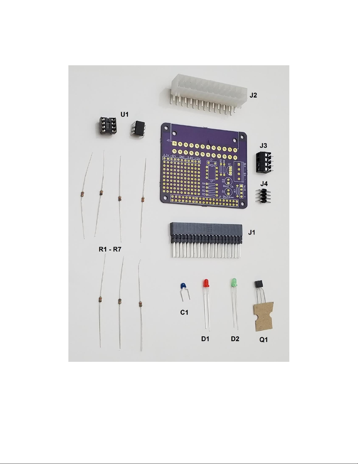
Figure 1: Parts Reference

PiRyte Mini ATX PSU
Installation and User Guide.
February 15, 2017
Copyright 2017 by Windhaven Consulting Inc and Pod Bay 3
Page 8 of 8
Warranty
Fully assembled PiRyte interface boards from the factory are warranted against manufacturing defects
for a period of one year from date of purchase. As the circumstances under which this product is
installed cannot be controlled, failure of this product due to installation problems will not be warranted.
Such issues include but are not limited to: applying over voltages to digital inputs, not using clamping
diodes on open collector outputs or trying to drive more current than the driver is capable, and
improperly changing the shunts on power jumpers causing the interface board, the Raspberry Pi, or both
to fail.
Unassembled kits are warranted for the parts only as home assembly cannot be controlled. However, if
you do find yourself with a non-working board and have exhausted all attempts to fix the issue, then the
board may be exchanged for a new kit at a discounted price.
Product that has failed for non-warranted reasons may be exchanged for new or equivalent functionality
at a discounted price. Please email us using the “Contact Us” page at http://www.piryteboards.com/ for
more details.
This manual suits for next models
1
Table of contents
Other Pod Bay 3 Power Supply manuals


