Texecom Premier Elite PSU200 User manual

INSTALLATION
MANUAL
PSU200 & PS200XP
Standalone & Integrated intelligent
Power Supply Units
INS314-8

15-06-2022 • Changes to battery ratings tables as per PCR01618

INS314-8 3/17
Content
1.0 Introduction 4 ............................................................................................................................
2.0 PCB Layout and Terminals 6 ....................................................................................................
3.0 Standby Battery 8 .....................................................................................................................
4.0 Installation 12 ............................................................................................................................
5.0 Wiring Diagrams 13 ...................................................................................................................
6.0 Specifications 15 ........................................................................................................................
7.0 Standards 16 ..............................................................................................................................
8.0 Warranty 16 ................................................................................................................................

INS314-8 4/17
1.0 Introduction
The Premier Elite PSU200 is a standalone intelligent 2.5 Amp power supply. The
Premier Elite PSU200XP is a PSU200 combined with a Premier Elite 8XP zone
expander to create a fully monitored power supply unit via the control panel
network. Both units are supplied in a metal housing which can accommodate either
two 7Ah batteries or a single 17Ah battery.
The PSU200XP is designed for use with the following Premier & Premier Elite
control panels:
Premier & Premier Elite 24/48/88/168 & 640
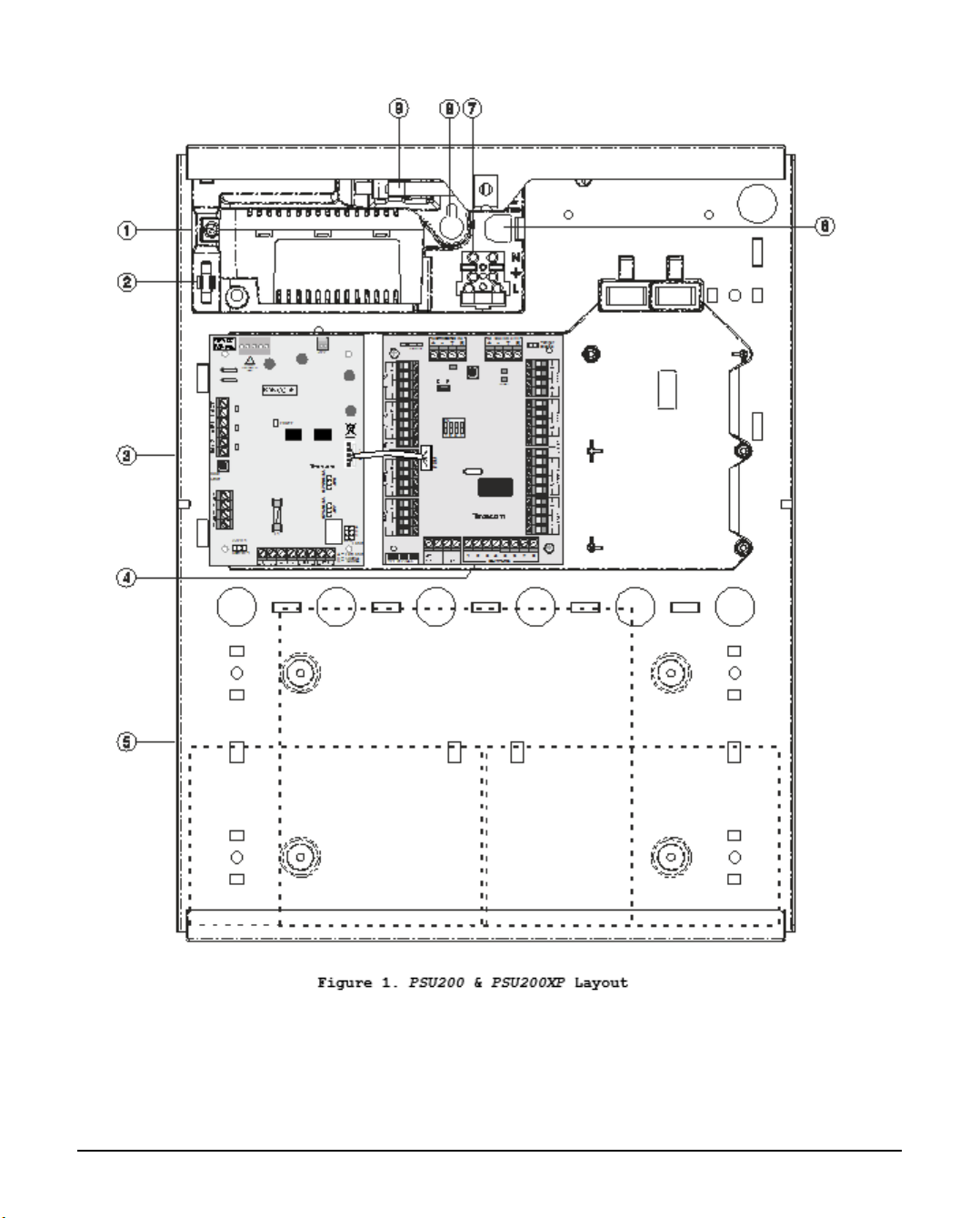
PSU200 and PSU200XP Layout
Texecom Power Supply1.
Spare Fuse2.
PSU200 & PSU200XP PCB3.
8XP zone expander PCB (only fitted on PSU200XP).4.
Standby battery space; 2 x 7Ah or 1 x 17Ah.5.
Mains cable entry and anchor point6.
Fused terminal block connector for mains supply.7.
Keyhole mounting and back tamper fixing point.8.
Tamper switch assembly9.
INS314-8 5/17
INS314-8 6/17
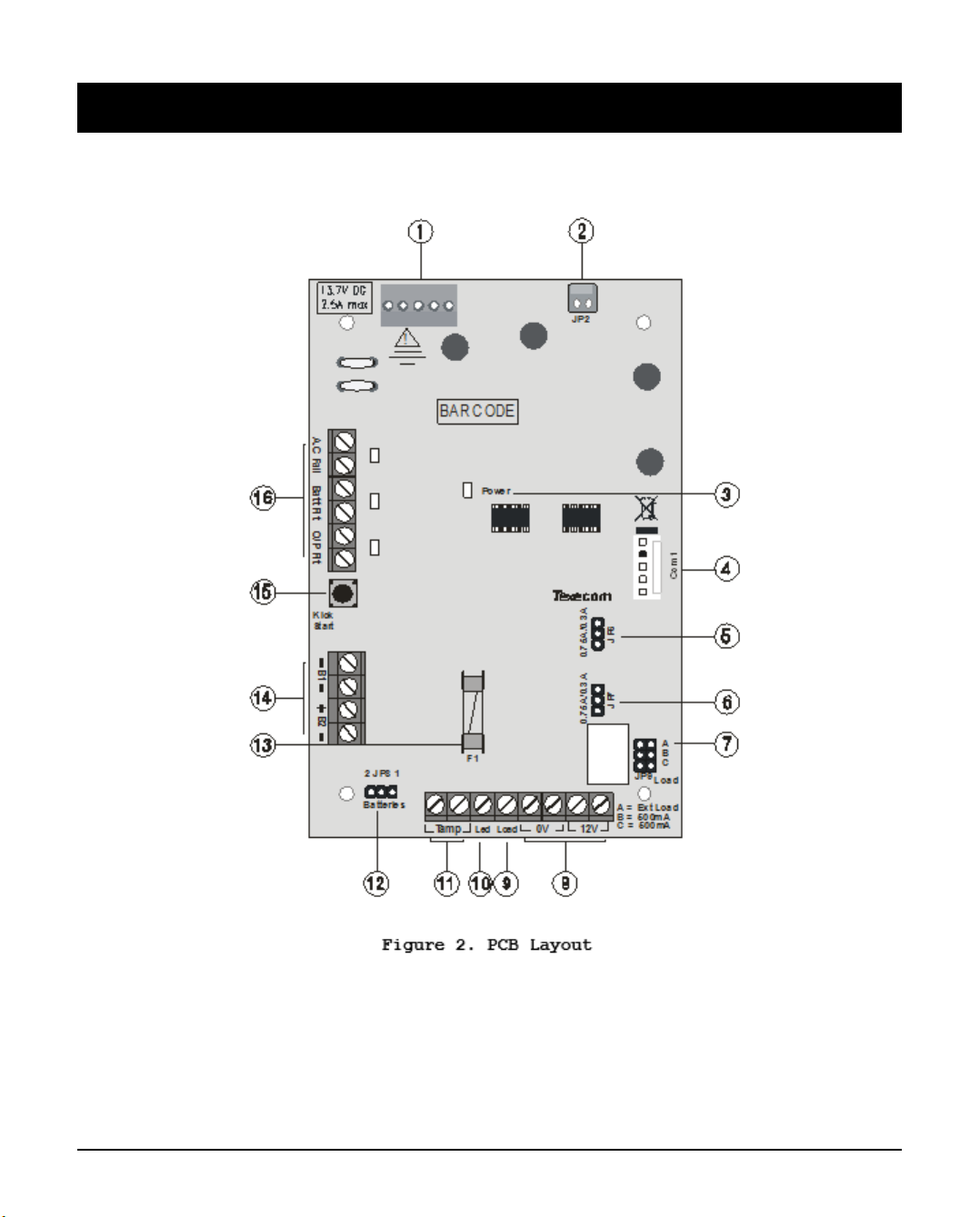
2.0 PCB Layout and Terminals
The figure below shows the PCB layout of the PSU200 and PSU200XP:
Texecom Power Supply Connection.1.
Connector to case tamper switch.2.
Power LED3.
Communication port (for connection to 8XP zone expander).4.
Battery 1 charge current selector (0.75A or 0.30A).5.
INS314-8 7/17
Battery 2 charge current selector (0.75A or 0.30A).6.
Battery load test options.7.
12V supply output.8.
External load for battery load test.9.
Not Used10.
Normally closed tamper output.11.
Number of batteries connected.12.
12V output protection fuse (1.6A).13.
Battery 1 and 2 connections.14.
Battery kick start switch.15.
Normally closed fault outputs and status led’s.16.
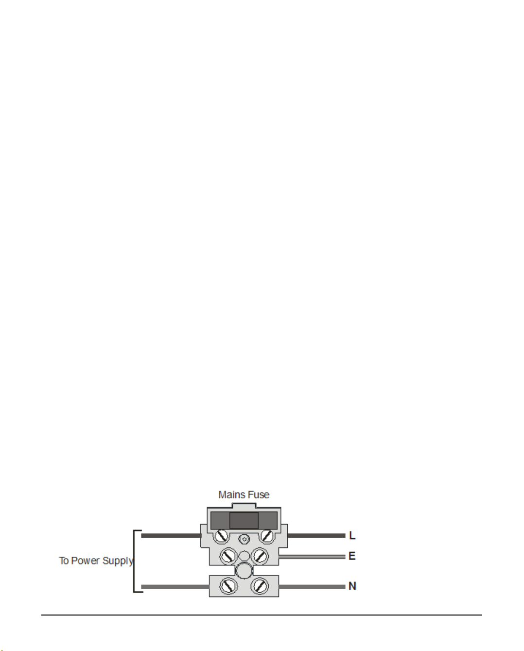
Mains Supply Connection
The mains supply is connected to a 3 way fused terminal block, which is fitted with
a 3A - 3.15A slow/medium blow protection fuse. The supply cabling should also
incorporate an accessible double pole disconnect device so that the supply can be
isolated.
TO14 INCERT Mains Input Connections: Min/Max cable size 18/14AWG
(0.82mm2/2.08mm2)
N
All electrical connections should be carried out by a qualified electrician.
After connecting the mains supply, fit the mains protection cover to the fused
terminal block, this can be found in the spares bag.
Secure the mains cable to the anchor point using a cable tie.

INS314-8 8/17
Supply Output
Two sets of terminals are provided to allow connection to auxiliary 12V devices.
The output is protected by a 1.6A fuse.
Tamper Protection
The power supply is both front and back tamper protected by the use of a tamper
switch which is connected to the PCB via a jumper plug JP2. When installing a
PSU200 the two tamper connections terminals should be connected to the tamper
or 24hour zone of the alarm control panel. The tamper connections are not
required for the PSU200XP as the tamper status is detected through the
communication port.
Fault Outputs and Indicators
Individual outputs and indicators are provided for the following faults:
A.C Fail: A normally closed set of contacts which open when the mains supply to
the unit fails. The associated red status led also lights when this fault is present.
Battery Fault: A normally closed set of contacts which open when a battery fault
is detected. The associated red status led also lights when this fault is present.
Output Fault: A normally closed set of contacts which open when the output fuse
(F1) fails or output voltage falls below 11V. The associated red status led also
lights when this fault is present.
When installing a PSU200 the fault outputs terminals should be connected to
individual zones or auxiliary inputs of the alarm control panel. The fault outputs are
not required for the PSU200XP as the fault status is detected through the
communication port.
3.0 Standby Battery
One or two 12V 7Ah batteries or one 12V 17Ah battery can be fitted inside the
power supply case to provide continued operation in the event of a mains supply
failure. The table below show various battery arrangements and recharge times
INS314-8 9/17
against rated output (maximum continuous current) for the required standby
period:
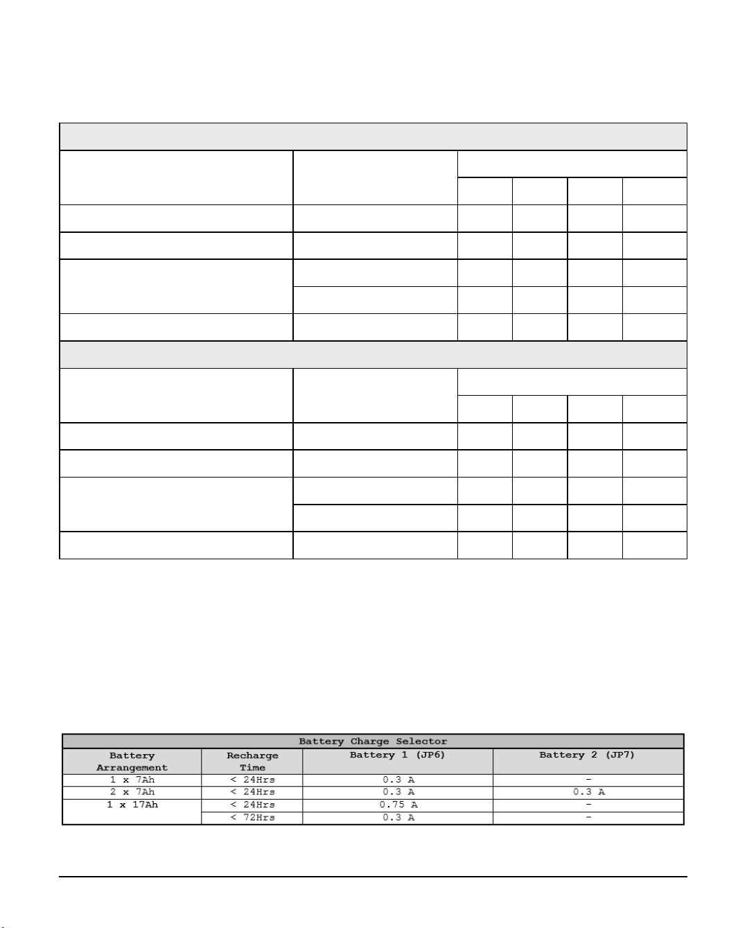
PSU200
Battery Arrangement Battery Charge Rated Output (Amps)
12h 24h 30h 60h
1 x 7Ah 0.3A 0.53A 0.24A 0.18A 0.071A
2 x 7Ah 0.3A 1.1A 0.53A 0.42A 0.18A
1 x 17Ah 0.3A 1.37A 0.66A 0.52A 0.23A
0.75A 1.37A 0.66A 0.52A 0.23A
1 x 18h 0.75A 1.4A 0.7A 0.55A 0.25A
PSU200XP
Battery Arrangement Battery Charge Rated Output (Amps)
12h 24h 30h 60h
1 x 7Ah 0.3A 0.46A 0.17A 0.11A 0.0A
2 x 7Ah 0.3A 1.0A 0.46A 0.35A 0.11A
1 x 17Ah 0.3A 1.3A 0.59A 0.45A 0.16A
0.75A 1.3A 0.59A 0.45A 0.16A
1 x 18Ah 0.75A 1.3A 0.63A 0.48A 0.18A
The tables of Rated Output were calculated assuming the battery was charged to
100%
The table below shows the setting for the battery charge jumpers JP6 and JP7 for
the various battery arrangements and recharge times:

INS314-8 10/17
The table below shows the battery standby and recharge times for both
EN50131-6, PD6662 and TO:31:
EN50131 Grade 1 Grade 2 Grade 3
Minimum Standby Period 12 hrs 12 hrs 30 hrs*
Maximum Recharge Time 72 hrs 72 hrs 24 hrs
PD6662 Grade 1 Grade 2 Grade 3
Minimum Standby Period 12 hrs 12 hrs 24 hrs**
Maximum Recharge Time 72 hrs 72 hrs 24 hrs
TO:31 Grade 1 Grade 2 Grade 3
Minimum Standby Period 12 hrs 24 hrs 24 hrs
Maximum Recharge Time 72 hrs 48 hrs 24 hrs
* 30h if MAINS FAIL is reported to ARC, otherwise 60h
** This time may be halved if mains failure is signalled to an ARC.
Deep Discharge Protection
The power supply has a deep discharge protection circuit that prevents the
standby battery from being fully discharged when the mains supply has failed. The
standby batteries will be electronically disconnected when the terminal voltage
reaches 9.0V. When powering up the power supply without a mains supply (battery
only), the ‘Kick-Start’ switch must be pressed in order to bring the battery into
circuit.
Battery Monitoring
Each battery is monitored independently, therefore, the number of batteries
connected to the PSU200/PSU200XP must be set using JP8. If JP8 is set to “1
Battery” then battery 2 is not monitored. The following conditions are monitored:

INS314-8 11/17
Presence: Each battery is tested every 30 seconds when the case tamper is
closed. If either battery is disconnected during this test a battery fault is
generated.
Load: The PSU200 tests the standby batteries every 24 hours by allowing the
batteries to power the PSU and connected devices for a period of 10 seconds.
During the load test the voltage and current drawn from each battery is measured
and if either battery cannot supply the full load, a battery fault is generated (see
Battery Load). The PSU200XP performs the same test, but the frequency and
duration of the test is controlled by the control panel.
Low Voltage: When the mains supply fails and the unit is powered from the
standby batteries, the voltage is continuously measured and if the battery voltage
drops below 11V a battery fault is generated.
Battery Load
In order to ascertain the status of the battery during the load test the PSU must be
put under a sufficient load. If the devices connected to the output of the PSU
already draw 1A or more, then this is a sufficient load during the battery load test.
If the devices connected to the output of the PSU draw less than 0.5A, then an
additional load is required for the battery load test. This can be easily achieved
using JP9:
If an external load is connected between EXT LOAD terminal and +12V then that
load will always be used during battery test. You don’t need a jumper setting for
this. If you don’t want an external load then don’t connect one.
JP9 – A = no extra load
JP9 – B = 500mA extra load
JP9 – C = 500mA extra load
A only = PSU Load + External Load (if any)

INS314-8 12/17
B only = PSU Load + External Load (if any) + 500mA
C only = PSU Load + External Load (if any) + 500mA
B + C = PSU Load + External Load (if any) + 1A
No jumpers fitted is the same as fitting jumper A, ie PSU Load + External Load (if
any)
(see items - and 9 of Figure 2).
4.0 Installation
Remove the screw from the front cover and carefully slide it upwards to1.
disengage the cover from the bottom clip.
Gently pull the cover towards you noting that earth is connected to a spade2.
terminal on the front cover.
Unplug the earth lead from the spade connection on the inside of the front3.
cover. The front cover can now be fully removed and placed to one side.
Position the base in the required location and mark at least four of the4.
available mounting holes. If the back tamper is required the keyhole must
also be marked.
Remove the base and drill and plug the holes.5.
Pass all necessary cables through the cable entries and fix the base to the6.
wall using not less than 30mm x No 10 screws.
Connect the mains cable to the fused mains terminal block.7.
Connect the terminals on the PCB as required, see Wiring Diagrams.8.
Fit the appropriate standby battery or batteries and connect the battery leads9.
to the battery terminals.
Apply mains power and check the operation of the power supply.10.
Refit the front cover, remembering to connect the earth lead to the front11.
cover.
Replace the front cover screw.12.
INS314-8 13/17
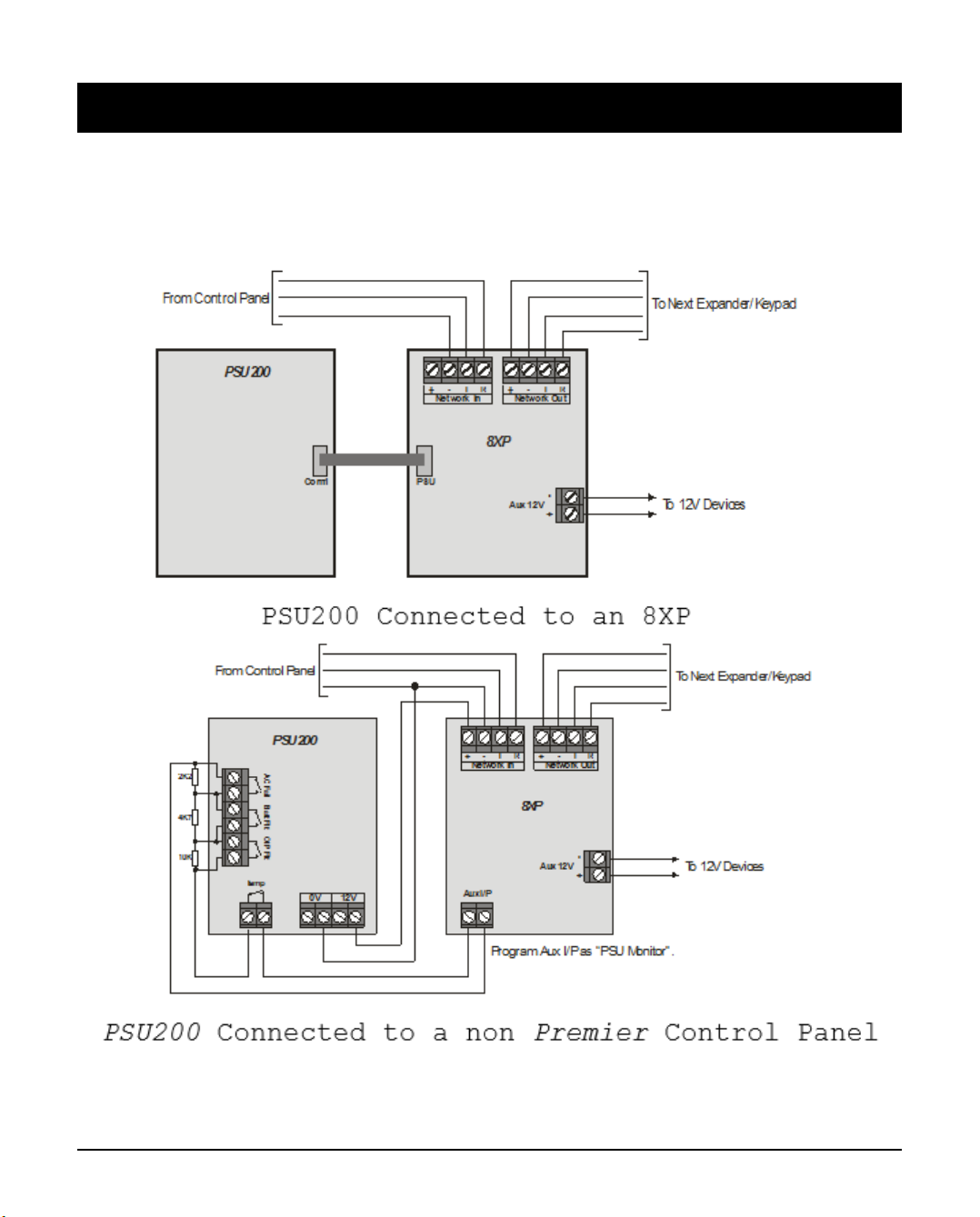
5.0 Wiring Diagrams
PSU200XP Connected to Premier Elite Control Panel
For a list of supported control panels, see Introduction.
INS314-8 14/17
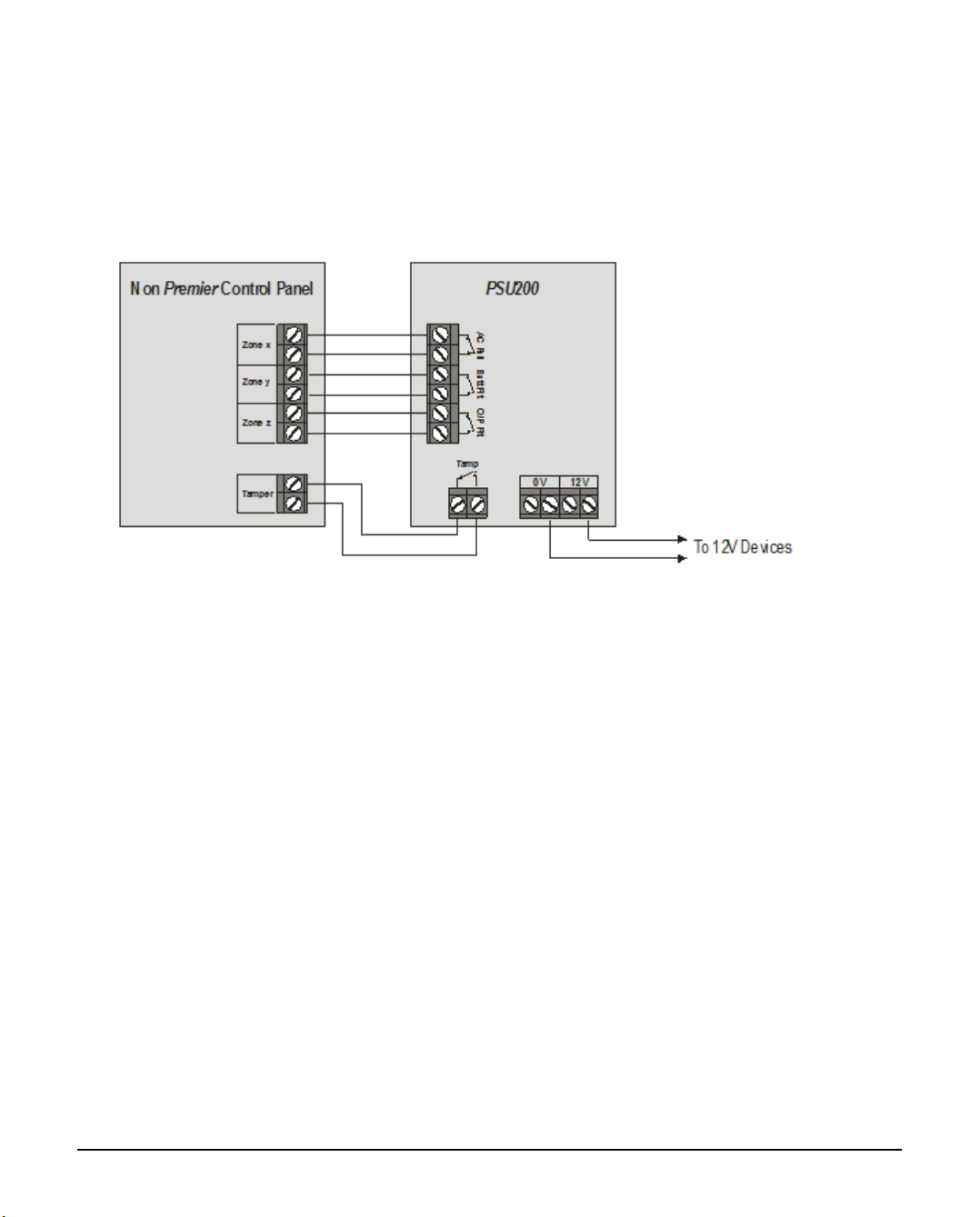
The PSU200 can be fully monitored by other makes of control panels, by
using the fault and tamper terminals. The zones on the control panel will
need to be programmed for PSU monitoring functionality. Please consult
the manufacturer’s instructions in order to ascertain whether the control
panel supports these zone types.

INS314-8 15/17
6.0 Specifications
Power Supply Type Type A
Mains supply 100V to 240V (+10%/-15%) @ 50Hz 1A max
Battery Voltage Charge 13.7Vdc +/- 2%
Output voltage Range 10.7V - 13.9V+/- 2%
TO14 INCERT Cable SpecMin/Max cable size 18/14AWG (0.82mm2/2.08mm2
Maximum Ripple
Voltage
0.5V pk-pk
Output Current Range 2.3A
Maximum available
current
1.5A (0.75A charge rate)
1.6A (2 x 0.3A charge rate)
1.6A (1 x 0.3A charge rate)
Rated output See page 4.
Current consumption PSU200 50mA PSU200XP 115mA
Fuses Mains = 3A (F3AL250V) or 3.15A (3.15AL250V)
F1 = 1.6A (F1.6AL250V)
Battery Type Sealed Lead Acid type
1 x 7Ah or 2 x 7Ah or 1 x 17Ah or 1 x 18Ah
Maximum Recharge
Time
See table on page 4
Battery charge current 0.3A or 0.75A (selectable)
Battery Low Voltage
Signal
11.0V (+/- 5%) at BATT terminal
Deep discharge cut-off 8.6V (+/- 5%) at BATT terminals
Output Fault Signal 10.7V (+/- 5%)
Over Voltage Protection 16V
Minimum energy level
of the SD in its charged
state
100% (to meet the backup periods specified in this
manual)
Location The PSU200 should be mounted within the
supervised premises.
Operating temperature -10°C to +50°C
Maximum humidity 95% non-condensing
Dimensions 310mm x 410mm x 100mm
Packed weight PSU200 3.9Kg (approx) PSU200XP 4.1Kg (approx)

INS314-8 16/17
7.0 Standards
Texecom declares that this product
complies with the requirements of the
following directives:
2014/30/EU EMC Directive
2014/35/EU LVD Directive
2011/65/EU RoHS Directive
The product therefore meets all the
requirements to enable it to be CE
marked.
Weee Directive: 2012/19/EU (WEEE
directive): Products marked with this
symbol cannot be disposed of as
unsorted municipal waste in the
European Union. For proper recycling,
return this product to your local supplier
upon the purchase of equivalent new
equipment, or dispose of it at
designated collection points. For more
information see: www.recyclethis.info
This product is a Type B Moveable device and is suitable for use in systems
designed to comply with EN 50131-1, EN50131-3 and PD6662 at Grade 3 and
Environmental Class II. The PSU200 and PSU200 XP are tested and approved to
EN50131-1, EN50131-6 and INCERT (TO:31) by Kiwa Telefication B.V.
8.0 Warranty
All Texecom products are designed for reliable, trouble-free operation. Quality is
carefully monitored by extensive computerised testing. As a result the Premier
Elite PSU200 and PSU200XP are covered by a two-year warranty against defects in
material or workmanship. As the Premier Elite PSU200 and PSU200XP are not a
complete alarm system but only a part thereof, Texecom cannot accept
responsibility or liability for any damages whatsoever based on a claim that the
Premier Elite PSU200 or PSU200XP failed to function correctly. Due to our policy of
continuous improvement Texecom reserve the right to change specification

INS314-8 17/17
without prior notice.
Premier & Premier Elite are trademarks of Texecom Ltd.
Other manuals for Premier Elite PSU200
2
This manual suits for next models
1
Table of contents
Other Texecom Power Supply manuals


